
Related Manuals for GE MDS TD220MAX


Summary of Contents for GE MDS TD220MAX
- Page 1 MDS™ TD220MAX Robust Communications for Positive Train Control MDS 05-6906A01, Rev. R DECEMBER 2018...
- Page 2 [This page intentionally left blank]...
-
Page 3: Table Of Contents
TABLE OF CONTENTS 1.0 INTRODUCTION ............................ 1 1.1 Key Product Features ..........................1 1.1.1 Authorization Features ......................1 1.2 Accessories and Spares ......................... 2 1.3 40-Watt Power Amplifier ......................... 2 2.0 PRODUCT DESCRIPTION ........................3 2.1 Front Panel Connectors and Indicators ....................3 3.0 INSTALLATION PLANNING ........................ - Page 4 5.6 PTP Configuration Menu ........................23 5.7 Security Configuration Menu ........................25 5.7.1 User Passwords Menu ......................26 Console/Telnet Lockout Security ....................26 5.8 Statistics/Logging Menu .......................... 27 5.8.1 STFP Logger Menu ......................28 5.8.2 Wireless Packet Statistics Menu ..................29 5.8.3 Dropped Packet Statistics Menu ..................
- Page 5 Copyright and Trademark This manual and all software described herein is protected by Copyright: 2018 GE MDS, LLC. All rights reserved. GE MDS, LLC reserves its right to correct any errors and omissions in this publication. RF Safety Notice (English and French) Concentrated energy from a directional antenna may pose a health hazard to humans.
- Page 6 These systems will reuse or recycle most of the materials found in this equipment in a sound way. Please contact GE MDS or your supplier for more information on the proper disposal of this equipment.
-
Page 7: Introduction
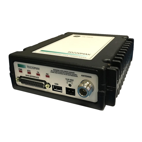
1.0 INTRODUCTION This manual is for users of the MDS TD220MAX Transceiver shown in Figure 1. It contains an overview of installation planning data, specifications, troubleshooting, and instructions for using the radio’s menu system. This manual is intended for technical personnel who perform network design, configuration, and troubleshooting of the equipment. -
Page 8: Accessories And Spares
Accessories and Spares Table 1 lists common accessories and spare items for the transceiver. Table 1. Accessories & Spare Items Accessory Description Part Number DIN Rail Mounting Bracket Kit Contains bracket for mounting the transceiver 03-4125A04 to standard 35 mm DIN rails commonly used in equipment cabinets and panels. -
Page 9: Product Description
2.0 PRODUCT DESCRIPTION The GE MDS TD220MAX is a 25-Watt 220 MHz GMSK data radio intended for bridging messages over the air between locomotives and wayside devices in rail applications or between ship and shore in maritime applications. The data interface is Ethernet and uses the UDP/IP-based Simple Timeslot/Frequency/Power Protocol (STFP), defined elsewhere. -
Page 10: Installation Planning
3.0 INSTALLATION PLANNING This section covers pre-installation factors that should be considered when installing the transceiver in the field. Careful planning will help achieve optimal performance from the transceiver. The specific details at an installation site may vary, but there are four main requirements for installing the transceiver in all cases: •... -
Page 11: Optional Din Rail Mounting
The transceiver may be used with several different antennas. The exact style and gain factor depend on the physical size and layout of your system. Connection is made to the radio via a N coaxial connector. Contact your factory representative for details for Antennas available from GE MDS for this radio. Feedlines 3.3.2... -
Page 12: Power
The table which follows, shows the approximate losses that will occur when using various lengths and types of coaxial cable in 200 MHz band. Regardless of the type used, the cable should be kept as short as possible to minimize signal loss. Table 2. -
Page 13: Grounding Considerations
Table 3. Current Consumption vs Input Power and Duty Cycle Voltage (V) RF Power Out (W) Duty Cycle (%) Current Required (A) Thermal Dissipation (W) 0 (RX) 13.8 0 (RX) 13.8 13.8 13.8 Grounding Considerations To minimize the chance of damage to the transceiver and connected equipment, a safety ground (NEC Class 2 compliant) is recommended which bonds the antenna system, transceiver, power supply, and connected data equipment to a single-point ground, keeping all ground leads as short as possible. -
Page 14: Adapter Board
Adapter Board 3.6.1 GE MDS has available a breakout adapter board that separates the DB25 connector into an Ethernet port, PPS port, as well as three COM connectors. This board is for controlled environment applications only. For additional details regarding the adapter board, view the “TD_RCL” adapter board instruction sheet located here http://www.gegridsolutions.com/app/resources.aspx?prod=td-series&type=9. -
Page 15: Usb
The radio provides a USB Port conforming to version 1.1 of the USB standard. This port is provided for features such as logging STFP messages to text files on a memory stick. Consult GE MDS for information on this feature. The pinout for this connector is given in the table below. -
Page 16: Antenna Connector
Antenna Connector The Antenna Connector is a type N female connector with 50-Ohm characteristic impedance. A suitable lightning arrestor such as a Polyphaser VHF50HN should be employed when indicated by applicable standards or codes. TD220MAX Technical Manual MDS 05-6906A01, Rev R... -
Page 17: Step-By-Step Installation
4.0 STEP-BY-STEP INSTALLATION In most cases, the steps given here are sufficient to install the transceiver. 1. Mount the transceiver. Attach the mounting brackets to the bottom of the transceiver case (if not already installed), using the four 6-32 x 1/4-inch (6 mm) screws supplied. Mounting bracket dimensions are shown in Figure 5 on Page 5. -
Page 18: Telnet Console
Telnet Console 4.1.2 NOTE It is not recommended to change the default IP settings via the Telnet interface. Networking changes should be done locally via the serial console and then deployed in the field. See the section above on modifying these networking parameters. On newer computers, the default telnet function on Windows machines may be disabled. -
Page 19: Installing Td220Max Firmware By Tftp
Firmware images are provided free-of-charge on the MDS Web site at: www.gemds.com. Use the product lookup to search for TD Series. Installing TD220MAX Firmware by TFTP 4.3.2 To use this function the user will need: • A PC with a TFTP server running. •... -
Page 20: Set Up A Ptp Base Unit
b. Set the IP Port on which the base will receive STFP messages from the Communication Manager. c. Set the IP Address of the Communication Manager to which timing markers and messages received from mobiles should be sent. d. Set the IP Port of the Communication Manager to which timing markers and messages received from mobiles should be sent. -
Page 21: Set Up An Ota Mobile Unit
Set Up an OTA Mobile Unit 1. Log in to the radio. 2. Go to the System Configuration Menu. 3. Set the timing source to OTA and allow the radio to reboot (factory-new units default to OTA, so this step may be skipped). 4. -
Page 22: Menu Interface
5.0 Menu Interface The menu interface can be reached via two ways; serially via the DB25 connector or by Telnet via the Ethernet Interface. This section will describe the different menus available on the radio. Configurable settings are followed by information in brackets. The information includes a comma- separated list of possible values then a semicolon and the default value. -
Page 23: Main Menu
Main Menu The next screen, the Main Menu is the entryway to all user-controllable features. The transceiver’s Device Name appears at the top of this and all other screens as a reminder of the unit that is currently being controlled. Figure 11. -
Page 24: Network Configuration Menu
Network Configuration Menu Figure 12. Network Configuration Menu • IP Configuration – Access to set the IP address, netmask, and gateway IP address of the radio. • SNMP Agent Configuration – Access to set SNMP configuration parameters. • Ethernet Address – Display only hardware address of the unit’s Ethernet port. IP Configuration Menu 5.2.1 Figure 13. -
Page 25: Snmp Agent Configuration Menu
SNMP Agent Configuration Menu 5.2.2 Figure 14. SNMP Agent Configuration Menu • SNMP Read Community – SNMP community string used for SNMPv1/SNMPv2c read access. This string can be up to 30 alphanumeric characters. • SNMP Write Community – SNMP community string used for SNMPv1/SNMPv2c write access. This string can be up to 30 alphanumeric characters. -
Page 26: System Configuration Menu
System Configuration Menu Figure 15. System Configuration Menu (Base) Figure 16. System Configuration Menu (Mobile) • Timing Source – The timing source used by the radio to precisely determine current time and the start of each second. Mobile radios are configured for OTA to synchronize with a base radio running GPS and/or PTP. -
Page 27: Stfp Configuration Menu
• External Alarm Sense – Configures the external alarm line (see Table 4. DB25 Serial Interface Pinouts) to be either HIGH or LOW when the radio is in an alarmed state. [Alarm High, Alarm Low; Alarm High] • Free Run – Base Radios Only – Allow over the air transmission despite the Time Synchronization Invalid alarm. -
Page 28: Radio Configuration Menu
Radio Configuration Menu Figure 18. Radio Configuration Menu • Enable External PA – If enabled, the radio ignores per message power values specified by STFP and forces transmissions at a lower power level suitable for driving the external PA (around 200 mW). -
Page 29: Gps Configuration Menu
GPS Configuration Menu Figure 19. GPS Configuration Menu • GPS NMEA Baud Rate – This is the baud rate used on the radio port to receive NMEA sentences. [1200, 2400, 4800, 9600, 19200, 38400, 57600, 115200; 9600 bps] • GPS PPS Polarity – Indicates if the TTL PPS Pulse is Active High ( ) or Active Low Positive Pulse Negative Pulse... - Page 30 Figure 21. PTP Configuration Menu - PTP Profile: Telecom • PTP Profile – Choose either as the PTP profile. None ITU-T G.8265.1 (Telecom profile) None uses multicast messaging. The uses unicast messaging with the ITU-T G.8265.1 (Telecom profile) clock specified by PTP Unicast Master. [None, ITU-T G.8265.1 (Telecom profile);...
-
Page 31: Security Configuration Menu
Security Configuration Menu Figure 22. Security Configuration Menu • Telnet Access – If “enabled”, the radio allows user to Telnet to the radio via Ethernet. If “disabled”, users must manage the radio via SNMP or the serial console. [enabled, disabled; enabled] •... -
Page 32: User Passwords Menu
It is recommended to change the default value of the passwords for security. However, once passwords have been changed, they can never return to the default values unless the radio is sent back to GE MDS for service. Console/Telnet Lockout Security TD220MAX release 1.2.15 introduces a lockout on serial and telnet console logins after repeated... -
Page 33: Statistics/Logging Menu
Statistics/Logging Menu Figure 24. Statistics / Logging Menu - Base Radio Figure 25. Statistics / Logging Menu - Mobile Radio • STFP Logger – Access the STFP Logger Menu. • Wireless Packet Statistics – Access the Wireless Packet Statistics Menu to view the number of messages passed over the air. -
Page 34: Stfp Logger Menu
STFP Logger Menu 5.8.1 Figure 26. STFP Logger Menu • STFP Log Enable – If “enabled”, the radio will send UDP messages to a log server. [enabled, disabled; disabled] • STFP Log Server – The IP address to send UDP messages for logging STFP traffic. [Any valid IP address;... -
Page 35: Wireless Packet Statistics Menu
Wireless Packet Statistics Menu 5.8.2 Figure 27. Wireless Packet Statistics Menu • Tx Beacons – The number of beacon messages transmitted over the air. Beacons are messages sent in the first timeslot of a second that contain no payload. If a message with payload is sent during the first-timeslot of a second, it is still used by OTA radios to synchronize time, but it is not included in this statistic. -
Page 36: Dropped Packet Statistics Menu
Dropped Packet Statistics Menu 5.8.3 Figure 28. Dropped Packet Statistics Sub Menu • Tx Dropped – The number of packets to be transmitted over the air that were dropped by the radio before sending. There can be various reasons for this. For example, an STFP message could not be properly decoded by the radio, or a message could not be transmitted because the radio is in an alarm state. -
Page 37: Ethernet Packet Statistics Menu
Ethernet Packet Statistics Menu 5.8.4 Figure 29. Ethernet Packet Statistics Menu • Packets Received – The number of packets received over Ethernet. • Packets Sent – The number of packets transmitted over Ethernet. • Bytes Received – The number of bytes for all packets received over Ethernet. •... -
Page 38: Event Log Menu
Event Log Menu 5.8.5 Figure 30. Event Log Menu • Current Alarms – Displays a list of the alarms currently active within the radio. • View Event Log – Opens the Event Log to view the historical list of radio events and alarms. •... -
Page 39: View Event Log Menu
View Event Log Menu 5.8.6 Figure 31. Event Log Submenu • This screen displays the event number, date and time, and event or alarm for each occurrence. Besides the cursor keys indicated, the letter keys u, d, p, n, h, and e may be used for navigating (U)p, (D)own, (P)g-Up, Pg-D(n), (H)ome, and (E)nd. -
Page 40: Gps Status Menu (Base Radios Only)
GPS Status Menu (Base Radios Only) 5.8.8 Figure 33. GPS Status Menu • GPS Fix Status – When the status is “Fix” the information onscreen is up-to-date, otherwise the information is stale. • Number of Satellites – Total satellites reported by the GPS receiver. •... -
Page 41: Device Information Menu
Device Information Menu Figure 35. Device Information Menu • Model – The model type of the radio. • Serial Number – The factory-assigned unique radio serial number. • Uptime – The number of elapsed hours, minutes, and seconds since the radio last rebooted. •... -
Page 42: Device Names Submenu
Device Names Submenu 5.9.1 Figure 36. Device Names Submenu • Device Name – Free-form field to enter a nickname for this radio. [40 characters max; Device Name] • Contact – Free-form field to indicate who to contact in case the radio needs service. characters max;... -
Page 43: Maintenance/Tools Menu
5.10 Maintenance/Tools Menu Figure 37. Maintenance / Tools Menu • Reprogramming – Access the Reprogramming submenu to upgrade the radio’s firmware. • Configuration Scripts – Access the Configuration Scripts submenu to save and restore the radio’s configuration to and from a text file via a TFTP server. •... -
Page 44: Reprogramming Menu
Reprogramming Menu 5.10.1 Figure 38. Reprogramming Menu • TFTP Host Address – The IP address of the TFTP server from which the new firmware image will be download. [Any valid IP address; 127.0.0.1] • Firmware Filename – The filename for the firmware image. This file must exist on the server. [40-character filename max;... -
Page 45: Configuration Scripts Menu
Configuration Scripts Menu 5.10.2 Figure 39. Configuration Scripts Menu • TFTP Host Address – The IP address of the TFTP server used for configuration script transfers. [Any valid IP address; 127.0.0.1] • Config Filename – The configuration script filename to transfer. [40-character filename max;... -
Page 46: Ping Utility Menu
Authorization Key – Enter an alphanumeric key to enable features on this device. • Authorized Features – The status of the features authorized for this device. NOTE Contact GE MDS to obtain an authorization key to enable additional features. TD220MAX Technical Manual MDS 05-6906A01, Rev R... -
Page 47: Radio Test Menu
Radio Test Menu 5.10.5 Figure 42. Radio Test Menu • Test State – Enable or disable the test. [disabled, enabled; disabled] • Test Transmit Frequency – The transmit test frequency. [216.00625-221.9875; 218.25 MHz] • Test Receive Frequency – The receive test frequency. [216.00625-221.9875;... -
Page 48: Communications Manager Menu
5.11 Communications Manager Menu Figure 43. Communications Manager Menu • CM Version – Access the menu to view the current installed Communications Manager firmware revision. • CM Provisioning – Access the menu to manage provisioning files for the Communications Manager. •... -
Page 49: Cm Version Menu
CM Version Menu 5.11.1 Figure 44. CM Version Menu This menu will display the current installed Communication Manager firmware bundled in the radio’s firmware. CM Provisioning Menu 5.11.2 Figure 45. CM Provisioning Menu • TFTP Host Address – The IP address of the TFTP server used for provisioning file transfers. [Any valid IP address;... -
Page 50: Cm Configuration Menu
CM Configuration Menu 5.11.3 Figure 46. CM Configuration Menu • TFTP Host Address – IP address of the TFTP server located on the network. [Any valid IP address; 127.0.0.1] • Filename – The filename of the configuration file to manage. [40 characters long;... -
Page 51: Cm Log Menu
CM Log Menu 5.11.5 Figure 48. CM Log Menu • TFTP Host Address – IP address of the TFTP server used for log file transfers. [Any valid IP address; 127.0.0.1] • Filename – The filename of the log file to manage. [40 characters length] •... -
Page 52: Troubleshooting
PWR LED blinking. Noted below, some alarms can be corrected by the user (noted with an asterisk (*)) while others may require returning the unit to GE MDS for diagnostics. Many alarms and events also have an SNMP trap associated to them for use in applications using SNMP. - Page 53 Table 8. Correcting Alarm Conditions Event Log Entry Generating Condition Clearing Condition or Action • Reboot the radio. If condition Unit encounters something System Error Please Reboot continues after reboot, contact that causes a system error. factory Technical Services. • Ethernet interface fails to Contact factory Technical Network Interface Error...
-
Page 54: Logged Events
Logged Events 6.1.3 The following events allow the transceiver to continue operation but do not make the PWR LED blink. Table 9. Logged Events Event Log Entry Description SNMP Trap Displays the valid type of time source that tod(21) Time Synchronization Valid: the radio is actively synchronized to. - Page 55 Table 9. Logged Events Event Log Entry Description SNMP Trap Console Access Locked for 5 Self-explanatory consoleLockdown(66) minutes Login Attempt Failed Self-explanatory loginFailed(67) In some cases, along with alarms mentioned in the previous section, additional GPS events may assist in the corrective methods for proper radio operation.
-
Page 56: Technical Specifications
Technical Specifications GENERAL Frequency Range 216-222 MHz, 12.5kHz bandwidth RECEIVER Maximum Usable Sensitivity –114 dBm at 10% PER (FEC enabled, wide deviation) –109 dBm at 10% PER (FEC enabled, narrow deviation) TRANSMITTER Carrier Power 2 – 25 Watts (33-44 dBm) Note: 2 W max for FCC part 90 with frequencies under 220 MHz Duty Cycle 25W / 30% Duty... -
Page 57: Acknowledgements
7.0 Acknowledgements TD220MAX incorporates ptpd (https://github.com/ptpd/ptpd): * Copyright (c) 2015 Wojciech Owczarek. * Copyright (c) 2014 Perseus Telecom. * Copyright (c) 2013-2014 Harlan Stenn, George N. Neville-Neil, Wojciech Owczarek, Jan Breuer. * Copyright (c) 2011-2012 George V. Neville-Neil, Steven Kreuzer, Martin Burnicki, Jan Breuer, Wojciech Owczarek,... - Page 58 * SUBSTITUTE GOODS OR SERVICES; LOSS OF USE, DATA, OR PROFITS; OR * BUSINESS INTERRUPTION) HOWEVER CAUSED AND ON ANY THEORY OF LIABILITY, * WHETHER IN CONTRACT, STRICT LIABILITY, OR TORT (INCLUDING NEGLIGENCE * OR OTHERWISE) ARISING IN ANY WAY OUT OF THE USE OF THIS SOFTWARE, EVEN * IF ADVISED OF THE POSSIBILITY OF SUCH DAMAGE.
- Page 59 TECHNICAL ASSISTANCE Technical assistance for GE MDS products is available from our Technical Support Department during normal business hours (8:30 A.M.–5:00 P.M. Eastern Time). When calling, please give the complete model number of the product, along with a description of the trouble/symptom(s) that you are experiencing.