
Related Manuals for GE VeriDri


Summary of Contents for GE VeriDri
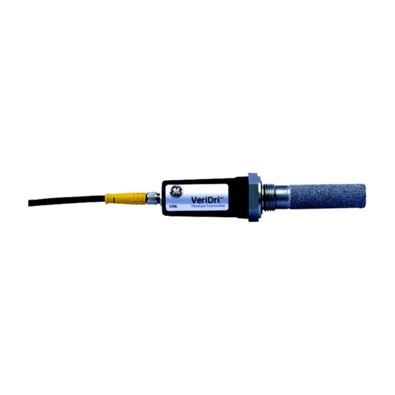
- Page 1 Measurement & Control Moisture VeriDri™ Moisture Transmitter User’s Manual 916-095 Rev. D March 2015...
- Page 3 Measurement & Control VeriDri™ Moisture Transmitter User’s Manual 916-095 Rev. D March 2015 www.ge-mcs.com ©2015 General Electric Company. All rights reserved. Technical content subject to change without notice.
- Page 4 [no content intended for this page]...
- Page 5 Auxiliary Equipment Local Safety Standards The user must make sure that he operates all auxiliary equipment in accordance with local codes, standards, regulations, or laws applicable to safety. VeriDri™ User’s Manual...
- Page 6 Make sure that operators and maintenance personnel have all safety equipment applicable to the auxiliary equipment. Examples include safety glasses, protective headgear, safety shoes, etc. Unauthorized Operation Make sure that unauthorized personnel cannot gain access to the operation of the equipment. VeriDri™ User’s Manual...
- Page 7 Preface Environmental Compliance Waste Electrical and Electronic Equipment (WEEE) Directive GE Measurement & Control Solutions is an active participant in Europe’s Waste Electrical and Electronic Equipment (WEEE) take-back initiative, directive 2012/19/EU. The equipment that you bought has required the extraction and use of natural resources for its production.
- Page 8 Preface [no content intended for this page] VeriDri™ User’s Manual...
-
Page 9: Table Of Contents
Moisture Sensor Specifications ....... . . 16 VeriDri™ User’s Manual... - Page 10 Contents [no content intended for this page] viii VeriDri™ User’s Manual...
-
Page 11: Introduction
F). It can also be provided to cover a number of moisture ranges from 0 to 10,000 PPMv. The VeriDri is supplied with one 4 to 20 mA analog output that is factory-configured for a specified range. The VeriDri is easy to install, operate and maintain. This manual includes the following sections: •... -
Page 12: Sample System Guidelines
Operating Instructions 2 Sample System Guidelines You can install the VeriDri transmitter either into a sample system or directly into the process. GE recommends that the unit be installed in a sample system to protect the probe from coming into contact with damaging elements in the process. - Page 13 Operating Instructions 2 Sample System Guidelines (cont.) Sample Cell Sample Sample Outlet Inlet Vent Figure 1: Sample System Example VeriDri™ User’s Manual...
-
Page 14: Inserting The Transmitter Into The System
Operating Instructions 3 Inserting the Transmitter into the System CAUTION! If you are mounting the VeriDri directly into the process line, you must consult GE for proper installation instructions and precautions before beginning the following procedure. Complete the steps below to install the VeriDri: Make sure the sintered or sheet stainless-steel shield is in place. - Page 15 3 Inserting the Transmitter into the System (cont.) Using a 1-1/8 in. wrench, tighten the probe securely into the system using the probe hex nut. CAUTION! Do not apply force on the transmitter module to tighten the unit into its fitting. Probe Hex Nut VeriDri™ User’s Manual...
-
Page 16: Making The Wiring Connections
*The blue and brown leads also produce a current output equivalent to 4 to 20 mA. Trim any unused leads back to the outer cable jacket, to remove the bare tinned wire and prevent accidental short circuits. The VeriDri is now ready for operation. VeriDri™ User’s Manual... - Page 17 Operating Instructions 4 Making Wiring Connections (cont.) Figure 2: Wiring Connections VeriDri™ User’s Manual...
-
Page 18: Operating The Transmitter
5.1 Powering Up After the VeriDri is wired as described in the previous section, you may apply power to the unit. The transmitter takes approximately 20 seconds to initialize and begin normal operation. The unit will meet specified accuracy in about 3 minutes. -
Page 19: Cleaning The Transmitter Probe
• Rubber or latex gloves. • An oven set at 50°C ± 2°C (122°F ± 3.6°F), for drying the probe • A 1-1/8 in. wrench Refer to the following sections to properly clean the probe. VeriDri™ User’s Manual... -
Page 20: Removing The Transmitter
Disconnect the cable from the transmitter module. Unscrew the stainless-steel shield from the probe mount, and carefully remove it without touching the sensor. CAUTION! Any attempt to open the module or remove the probe from the module will void your warranty. Shield VeriDri™ User’s Manual... -
Page 21: Soaking The Sensor And Shield
Remove the shield from the hexane or toluene. Carefully replace the shield over the exposed sensor, without touching the sensor Place the sensor with the installed shield in an oven set at 50°C ± 2°C (122°F ± 3.6°F) for 24 hours. VeriDri™ User’s Manual... -
Page 22: Evaluating The Probe
5 times the previous cleaning sequence, until two consecutive ambient air readings are within ±2°C (±3.6°F). If the above cleaning procedure does not result in accurate readings, contact GE for assistance. VeriDri™ User’s Manual... -
Page 23: Specifications
0 to 10 PPMv • 0 to 100 PPMv • 0 to 1000 PPMv • 0 to 10,000 PPMv PPMv ranges are based on a constant pressure, which was provided Note: at the time of the order. VeriDri™ User’s Manual... -
Page 24: Electronics
Max. Loop Resistance: R = 50 Ω × (PSV–7), • where PSV = Power Supply Voltage Example: For a PSV = 24 VDC, R = 50 Ω × (24–7) = 850 Ω • Cable: 2 m, standard (consult factory for custom lengths) VeriDri™ User’s Manual... -
Page 25: Mechanical Specifications
Overall: 8.51 × 1.125 in. (21.62 × 2.86 cm) • Electronics Module w/cable: 5.93 × 1.125 in. (15.06 × 2.86 cm) • • Weight: 5 oz (140 g) 3/4-16 UNF-2A 1.125 [28.58] 3.35 [85.10] 2.58 [65.53] 2.58 [65.53] CABLE BEND ALLOWANCE VeriDri™ User’s Manual... -
Page 26: Moisture Sensor Specifications
Thin-film aluminum oxide moisture sensor probe Calibration Each sensor is individually computer-calibrated against known moisture concentrations, traceable to NIST Calibration Interval Factory sensor recalibration by GE Sensing is recommended every 6-12 months, depending on the application Calibration Data Factory-calibrated, stored in memory... - Page 27 Warranty Warranty Each instrument manufactured by GE Sensing is warranted to be free from defects in material and workmanship. Liability under this warranty is limited to restoring the instrument to normal operation or replacing the instrument, at the sole discretion of GE Sensing. Fuses and batteries are specifically excluded from any liability.
- Page 28 AUTHORIZATION NUMBER (RAN), and shipping instructions for the return of the instrument to a service center will be provided. If GE Sensing instructs you to send your instrument to a service center, it must be shipped prepaid to the authorized repair station indicated in the shipping instructions.
- Page 29 1100 Technology Park Drive Billerica, MA 01821 declare under our sole responsibility that the VeriDri™ Moisture Transmitter to which this declaration relates, is in conformity with the following standards: • EN 61326-1: 2006, Class A, Table 2, Industrial Locations • EN 61326-2-3: 2006 •...
- Page 30 [no content intended for this page]...
- Page 32 Customer Support Centers U.S.A. The Boston Center 1100 Technology Park Drive Billerica, MA 01821 U.S.A. Tel: 800 833 9438 (toll-free) 978 437 1000 E-mail: sensing@ge.com Ireland Sensing House Shannon Free Zone East Shannon, County Clare Ireland Tel: +35 361 470200 E-mail: gesensingsnnservices@ge.com An ISO 9001:2008 Certified Company www.ge-mcs.com/en/about-us/quality.html...