
Related Manuals for GE DewPro MMY31


Summary of Contents for GE DewPro MMY31
- Page 1 GE Industrial Sensing DewPro MMY31 General Eastern Trace Moisture Transmitter Installation and Operation Manual...
- Page 2 GE Industrial Sensing DewPro MMY31 General Eastern Trace Moisture Transmitter Installation and Operation Manual A40251548A September 2005 DewPro MMY31 is a General Eastern Instruments product. General Eastern Instruments has joined other GE high-technology sensing businesses under a new name—GE Industrial Sensing.
- Page 3 If a GE Infrastructure Sensing, Inc. instrument malfunctions within the warranty period, the following procedure must be completed: 1. Notify GE Infrastructure Sensing, Inc., giving full details of the problem, and provide the model number and serial number of the instrument.
-
Page 4: Table Of Contents
September 2005 Table of Contents Chapter 1: General System Information Unpacking and Inspection ............. . 1-1 Unit Description . - Page 5 Chapter 1...
-
Page 6: Chapter 1: General System Information
General System Information Unpacking and Inspection ........1-1 Theory of Operation . -
Page 7: Unpacking And Inspection
September 2005 Unpacking and Upon receipt of the DewPro MMY31, examine the shipping carton Inspection for broken or open packing, distortion, or any other evidence of mishandling. If inspection indicates damage to the unit or any of its components, notify the carrier (within 15 days of delivery) and request an inspection. - Page 8 September 2005 Table 1: Model Number Configuration Certification/Approvals: Standard Certification (not certified) FM IS Cl. I, II, III, Div. 1; Grps. A-G FM XP Cl. I, Div. 1; Grps. A-D FM NI Cl. I, Div. 2, Grps. A-D; Cl. II, III, Div. 1; Grps. E-G ATEX 3GEEx nA EEx 11C T4 Other Process Connection:...
-
Page 9: Unit Description
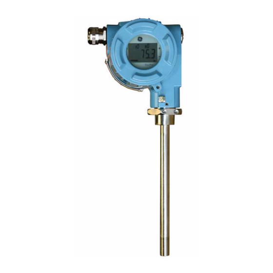
September 2005 Unit Description The DewPro MMY31 trace moisture transmitter is a loop-powered dewpoint measuring device. The transmitter includes a sensor element, a stainless steel probe, a weather-proof enclosure, microprocessor electronics, and assorted fittings, all in a compact assembly. It is designed to be installed “in-line.” Various types of mounting hardware, such as flange and compression fittings, are available for mounting into a process chamber or pipe. - Page 10 Chapter 2...
-
Page 11: Chapter 2: Installation
Installation Mounting the MMY31 (cont.) ........2-2 Wiring Configurations . -
Page 12: Mounting The Mmy31
Figure 2-1 below shows the dimensions of the standard MMY31. 5.43 (138) *without display 4.64 (118)* 4.25 (108) 9.45 0.79 (20) (240) Dimensions are in inches (millimeters). 0.50 (12.7) Figure 2-1: DewPro MMY31 Outline and Compression Fitting Installation... - Page 13 September 2005 Mounting the MMY31 Mount the MMY31 using a compression fitting connection. Be certain that the tip of the probe does not touch the inside wall of the (cont.) pipe. IMPORTANT: Ensure that your probe has a stainless steel ferrule, which is required for use in pressurized systems.
-
Page 14: Wiring Configurations
Note: If the DewPro is equipped with an optional display/user interface, please refer to Chapter 4. Figure 2-3 below illustrates various power supplies and displays for use with the DewPro MMY31. ’ 24 VDC (12...28 VDC) Sensing... -
Page 15: In A Normal Environment
A standard two-wire, stranded cable can be used in a normal environment to interconnect the DewPro with the power source. In Environments with The DewPro MMY31 meets the EMC requirements of IEC 61326 for Severe Electrical Noise equipment used in industrial locations. The MMY31 passed all tests to the standards IEC 61000-4- to the performance criterion A. -
Page 16: General Wiring Instructions
September 2005 General Wiring To wire the DewPro MMY31: Instructions 1. Unscrew the cap on the terminal side of the unit (has a DewPro label). 2. Loosen the cable gland located on the side of the unit. 3. Feed the cable through the conduit opening. - Page 17 Chapter 3...
-
Page 18: Chapter 3: Troubleshooting
Troubleshooting The Loop Current is Out of Range....... . . 3-1 There Is No Current . -
Page 19: The Loop Current Is Out Of Range
September 2005 The Loop Current is Out The loop current is outside the range of 4-20 mA, as shown on the of Range display or the current meter. For an example of error current at 22mA, see below. Solution The process dewpoint is out of range. If the dewpoint is above +10°C (+50°F), the current will go to 22 mA. - Page 20 Chapter 4...
- Page 21 Optional Display/User Interface Installation........... . . 4-1 Programming Matrix .
-
Page 22: Chapter 4: Optional Display/User Interface
September 2005 Installation If the DewPro is equipped with an optional display/user interface, follow the procedure below to access the buttons. Figure 4-1: Dewpro with Display Removing the Display 1. Unscrew and remove the protective windowed lid from the DewPro (as shown in Figure 4-1 above), exposing the display module below. -
Page 23: Programming Matrix
For users of other GE Sensing equipment, this matrix format may be familiar. The following describes the features and usage of the various matrix locations as they apply to the MMY31. - Page 24 Table 4-1: Matrix Options MMY31 Select Units Loop #1 at Fault Display Moisture 0 = °C 0 = –10% Value 1 = °F 1 = 110% 35 = ppm 2 = Hold Dewpoint Dewpoint °C 4 mA °C 20 mA 20 mA Pressure ppm Output...
-
Page 25: Push Buttons - Special Functions
September 2005 Push Buttons - Special Functions Reset to “Normal” Display Pressing the V and H buttons simultaneously returns the user to VH 00 (normal display). Display Only Five (5) matrix locations are for display only and may not be changed by the user (see Table 4-1 on page 4-3). -
Page 26: Matrix Functions
September 2005 Matrix Functions This section describes the functions available to the user through the matrix, grouped by common function areas (refer to Table 4-1 on page 4-3). Each function is accessed by moving to its specified location within the matrix. Display and Output Mode Table 4-2: Display and Output Mode Functions Function... -
Page 27: Special Calibration
September 2005 Special Calibration Table 4-3: Special Calibration Functions Function Location Description The process pressure constant is entered in bar (absolute), and is used to calculate ppm . The moisture unit ppm is the ratio of water vapor pressure to the total process pressure and is, therefore, independent of the process pressure. -
Page 28: Mode Of Operation
September 2005 Mode of Operation Table 4-4: Mode of Operation Functions Function Location Description Any number other than “50” will lock the instrument settings from Input Locking VH 89 inadvertent or unauthorized changes. (The instrument is unlocked only at “50.”) In the event of a system fault, this field displays the diagnostic error code for the fault encountered. - Page 29 Chapter 5...
-
Page 30: Specifications
Specifications Technical Specifications ......... 5-1 Optional Onboard Display with User Interface . -
Page 31: Technical Specifications
September 2005 Technical Specifications Sensing Element: Planar aluminum oxide sensor Measurement Range: –130° to +50°F (–90° to +10°C) dew point temperature. 0 to 10, 0 to 100, 0 to 1000 ppm (fully adjustable with integral display) Recommended 12 months, depending on the application Recalibration Cycle: Calibration Accuracy: ±3.6°F (±2°C) dew point at 77°F (25°C) -
Page 32: Optional Onboard Display With User Interface
September 2005 Optional Certifications/ FM IS Cl. I, II, III, Div. 1, Grps. A-G, T5 Approvals FM XP-IS Cl. I, Div. 1, Grps. A-D, T5 FM NI Cl. I., Div. 2, Grps. A-D, T4A DIP Cl. II, III, Div. 1, Grps. E-G, T5 ATEX II 3G EEx nA IIC T4 Optional Onboard The optional onboard display with user interface uses a matrix... - Page 33 GE Industrial DECLARATION Sensing CONFORMITY GE Industrial, Sensing 1100 Technology Park Drive Billerica, MA 01821 declare under our sole responsibility that the ® DewPro MMR30 Moisture Transmitter Probe ® DewPro MMR31 Moisture Analyzer ® DewPro MMY30 and MMY31 Dew Point Transmitters ®...
- Page 34 GE Industrial DECLARATION Sensing CONFORMITE GE Industrial, Sensing Nous, 1100 Technology Park Drive Billerica, MA 01821 déclarons sous notre propre responsabilité que les ® DewPro MMR30 Moisture Transmitter Probe ® DewPro MMR31 Moisture Analyzer ® DewPro MMY30 and MMY31 Dew Point Transmitters ®...
- Page 35 GE Industrial KONFORMITÄTS- Sensing ERKLÄRUNG GE Industrial, Sensing Wir, 1100 Technology Park Drive Billerica, MA 01821 erklären, in alleiniger Verantwortung, daß die Produkte ® DewPro MMR30 Moisture Transmitter Probe ® DewPro MMR31 Moisture Analyzer ® DewPro MMY30 and MMY31 Dew Point Transmitters ®...
- Page 36 1100 Technology Park Drive Billerica, MA 01821-4111 Web: www.gesensing.com Ireland Shannon Industrial Estate Shannon, County Clare Ireland...