Advertisement
Quick Links
®
MAXPRO
NVR PE Quick Install Guide
Document 800-12139V1 – Rev B – 05/2013
Introduction
Thank you for purchasing a Honeywell MAXPRO
1. Unpack Everything
Check that the items received match those listed on the order form and packing slip. The packing box should include:
• Power cord
• Keyboard (PS/2)
• Mouse (PS/2)
• This guide
• Video storage hard drives
Note
Other peripheral hardware (owner supplied) will also be needed for your installation, such as cameras, network
equipment, a monitor, and an optional keyboard controller.
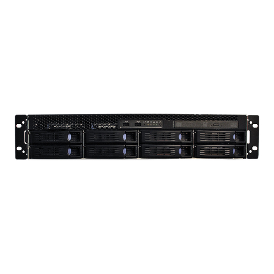
2. Installing Unit
Mounting the MAXPRO NVR Unit in a Rack and Installing Hard Drives
1.
Remove the bezel from the front of the unit. To remove the bezel, turn the two bezel key locks clockwise, and then pull
the bezel away from the unit.
2.
The MAXPRO NVR PE unit should be mounted with the supplied rail hardware kit. The kit allows the MAXPRO NVR PE
unit to slide in and out of the rack it is mounted in and provides rear support for the chassis. Refer to the installation
instructions included with the rail hardware kit.
3.
Install the supplied video storage hard drives in the hard drive slots located on the front of the unit. The drives are
numbered from 1 to 10, from the top left to the bottom right.
Note
The video storage hard drives are pre-configured for RAID 5 in the factory but can be reconfigured for RAID 6 if
required, however there will be less usable video storage space.
4.
Replace the bezel on the front of the unit. To replace the bezel, align the bezel key locks with the handles on the front
plate of the unit, and then slide the bezel into place. Turn the bezel key locks counterclockwise to secure the bezel.
2
1
PWR
Hard drive release button.
Bezel key lock (×2)
3. Connecting Hardware
Rear Panel Connections
1
3
5
16
17
2
4
# Connector
Connects to...
1
DIN-8 Connector
PC PS/2 mouse
2
DIN-8 Connector
PC PS/2 keyboard
3
USB Port
Various devices
4
USB Port
Various devices
5
COM1 Port
6
DB-15 VGA Connector
Monitor
7
Gigabit LAN1- Camera Network Port
Network *
8
Gigabit LAN2 - Client Network Port
Network *
* Network connectors have two LEDs:
•
Link LED (left) indicates the connection speed
(yellow = 1 Gbps, green = 100 Mbps).
•
Activity LED (right) flashes yellow when active.
Keyboard and Mouse
Before powering up the MAXPRO NVR PE, connect the supplied PS/2 keyboard and mouse to the DIN-8 connectors at the
rear of the unit.
Keyboard Controller
Follow the documentation that was included with your keyboard controller to connect it to the MAXPRO NVR PE unit through
the network.
®
NVR PE. Before installing your NVR, please read this guide carefully.
• Rail hardware kit with instructions for rack mount installations
• MAXPRO NVR Client Software (Single Site) and Server
Software DVD (includes manuals)
• MAXPRO Viewer Multi-Site Viewing Software Kit
(includes DVD and Quick Install Guide)
• Recovery DVD
9
10
11
12
13
6
7
8
# Connector
Connects to...
9
Blank
N/A
10Blank
N/A
11SAS Connector
External Storage/
Optional JBOD expansion
12Blank
N/A
13Blank
N/A
14Blank
N/A
15Blank
N/A
16AC Power Connector
AC power
17AC Power Connector
AC power
Dual Network Configuration
Local Monitor
(Configuration only)
USB
CAT5e
H4D2F1
HD4HDIH
Honeywell and Third-Party IP
Cameras and Encoders
Honeywell IP and analog cameras and encloder: Contact your dealer to purchase.
Network Connections
Connect a network PoE switch to the camera network port at the rear of the MAXPRO NVR unit. Connect your cameras to
the network PoE switch with CAT5 Ethernet cables. Optionally, connect the client workstation network port to your client
workstation network via a network switch. This allows remote access to your NVR. The default client workstation network IP
address must be changed to an available static IP address on your client workstation network.
Monitor(s)
Connect a VGA monitor. The recommended setting for your monitor is 1280 × 1024 pixels (resolution). Refer to the
®
MAXPRO
properties. The local VGA monitor can be used to configure the NVR, however continuous local video monitoring is not
recommended.
4. Powering Up the Unit
Note
Honeywell recommends using an uninterruptible power supply (UPS) for the MAXPRO NVR PE unit, the camera
network switch, and the cameras to ensure that the MAXPRO NVR PE unit can continue to record video during a
power outage.
MAXPRO NVR PE Power On Sequence
1.
Turn on the camera(s) and other hardware connected to the MAXPRO NVR PE unit.
Note
Honeywell recommends turning on the cameras before turning on the MAXPRO NVR PE unit since IP cameras can
take up to two minutes to boot up. Online cameras can be easily discovered by the unit after startup. It is also
recommended to turn on other associated network components, such as a network switch or router, before turning
on the MAXPRO NVR PE.
2.
Press the power button on the front of the MAXPRO NVR PE unit (the power button is labeled 6 in the image below).
3.
After powering on the unit, you are prompted to log on. The default user is user name: Administrator, password:
Password1. The user name and password are case sensitive.
Front Panel
14
15
No.
LEDs, Buttons, Ports
1
LAN2 LED (Client Port)
2
LAN1 LED (Camera Port)
3
HDD LED
4
Power LED
5
Reset button
6
Power button
7
USB port
8
DVD Drive LED
9
DVD Drive button
10
HDD Activity/Ready LED
HDD Failure LED
®
MAXPRO
NVR PE
USB
VGA
Camera Network Port
Client Workstation Network Port
(default 192.168.1.101)
(default 172.25.254.101)
Client Workstation Network
Camera Network PoE Switch
Switch
CAT5
CAT5e
CAT5e
CAT5e
CAT5e
HCD2F
HCD5HIH
Encoder
H3D2F1
HD3HDIH
Analog Cameras
NVR 2.5 Commissioning and Installation Guide for more information on configuring the monitor display
1 2 3 4 5
10
Color
Behavior
Yellow
On = There is client network activity.
Yellow
On = There is camera network activity.
Yellow
On = There is OS hard drive activity.
Green
On = The system is powered on.
Off = The system is powered off.
Black
Resets the unit.
Black
Powers on the unit.
—
Receives a USB device.
Green
On = There is DVD activity.
Black
Opens the DVD tray.
Blue
On = Hard drive is inserted and detected.
Flashing = System is accessing the hard drive.
Off = Hard drive is not detected.
Red
On = The hard drive is detected as a failure by the host.
Flashing = RAID rebuilding.
Off = There is no hard drive, or the hard drive is operating normally.
Mobile Devices
Router/
Firewall
Network
Wireless
Router
CAT5
Client Workstation
6
7
8 9
Document 800-12139V1 – Rev B –05/2013
Advertisement

Related Manuals for Honeywell MAXPRO PE


Summary of Contents for Honeywell MAXPRO PE
- Page 1 Note Honeywell recommends turning on the cameras before turning on the MAXPRO NVR PE unit since IP cameras can take up to two minutes to boot up. Online cameras can be easily discovered by the unit after startup. It is also recommended to turn on other associated network components, such as a network switch or router, before turning on the MAXPRO NVR PE.
-
Page 2: Advanced Features
© 2013 Honeywell International Inc. All rights reserved. No part of this publication may be reproduced by any means without written www.honeywellvideo.com permission from Honeywell. The information in this publication is believed to be accurate in all respects. However, Honeywell cannot +1.800.323.4576 (North America only)