Table of Contents
Advertisement
Advertisement
Table of Contents

Related Manuals for Cisco UCS B200 M5


Summary of Contents for Cisco UCS B200 M5
- Page 1 Cisco UCS B200 M5 Blade Server Installation and Service Note First Published: 2017-07-14 Last Modified: 2017-08-25 Americas Headquarters Cisco Systems, Inc. 170 West Tasman Drive San Jose, CA 95134-1706 http://www.cisco.com Tel: 408 526-4000 800 553-NETS (6387) Fax: 408 527-0883...
- Page 2 Cisco and the Cisco logo are trademarks or registered trademarks of Cisco and/or its affiliates in the U.S. and other countries. To view a list of Cisco trademarks, go to this URL: www.cisco.com/go/trademarks . Third-party trademarks mentioned are the property of their respective owners. The use of the word partner does not imply a partnership relationship between Cisco and any other company.
-
Page 3: Table Of Contents
Servicing a Blade Server C H A P T E R 3 Replacing a Drive Removing a Blade Server Drive Installing a Blade Server Drive Removing a Blade Server Cover Cisco UCS B200 M5 Blade Server Installation and Service Note... - Page 4 Memory Performance Memory Mirroring and RAS Installing a Virtual Interface Card in the mLOM Slot Installing a Rear Mezzanine Module in Addition to the mLOM VIC NVIDIA P6 Graphics Processing Unit Cisco UCS B200 M5 Blade Server Installation and Service Note...
- Page 5 Enabling the Trusted Platform Module Technical Specifications C H A P T E R 4 Physical Specifications for the Cisco UCS B200 M5 Blade Server NVIDIA Licensing Information A P P E N D I X A NVIDIA GRID License Server Overview...
- Page 6 Contents Cisco UCS B200 M5 Blade Server Installation and Service Note...
-
Page 7: Preface
Terminal sessions and information that the system displays appear in this font. CLI commands CLI command keywords appear in this font. Variables in a CLI command appear in this font. Cisco UCS B200 M5 Blade Server Installation and Service Note... - Page 8 Use the statement number provided at the end of each warning to locate its translation in the translated safety warnings that accompanied this device. SAVE THESE INSTRUCTIONS Cisco UCS B200 M5 Blade Server Installation and Service Note viii...
-
Page 9: Related Cisco Ucs Documentation
Related Cisco UCS Documentation Documentation Roadmaps For a complete list of all B-Series documentation, see the Cisco UCS B-Series Servers Documentation Roadmap available at the following URL: http://www.cisco.com/go/unifiedcomputing/b-series-doc. For a complete list of all C-Series documentation, see the Cisco UCS C-Series Servers Documentation Roadmap available at the following URL: http://www.cisco.com/go/unifiedcomputing/c-series-doc. - Page 10 Preface Obtaining Documentation and Submitting a Service Request Cisco UCS B200 M5 Blade Server Installation and Service Note...
-
Page 11: Overview
• A mini-storage module with dual SATA 3.0 M.2 cards or secure digital (SD) cards You can install up to eight UCS B200 M5 blade servers in a UCS 5108 chassis, mixing with other models of Cisco UCS blade servers in the chassis if desired. -
Page 12: External Features Overview
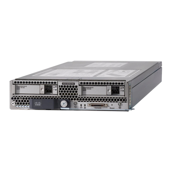
Overview External Features Overview Subject to chassis power configuration. Note Figure 1: Cisco UCS B200 M5 Blade Server Front Panel Asset pull tag Blade ejector handle Ejector thumb screw Drive bay 1 Drive bay 2 Power button and LED Network link status LED... - Page 13 You can control the blinking in UCS Manager or by using the blue locator button/LED. Activity Inactive. (Disk Drive) Green Outstanding I/O to disk drive. Cisco UCS B200 M5 Blade Server Installation and Service Note...
-
Page 14: Buttons
If the desired power state for a service profile associated with a blade server is set to "off," using the power button or Cisco UCS Manager to reset the server will cause the desired power state of the server to become out of sync with the actual power state and the server may unexpectedly shut down at a later time. -
Page 15: Drive Bays
Drive Bays The Cisco UCS B200 M5 blade server has a front mezzanine slot that can support either a storage module or a graphics processing unit (GPU). The storage module has two drive bays that can be configured with any combination of 2.5-inch SAS, SATA, or NVMe drives. - Page 16 Overview Graphics Processing Unit Cisco UCS B200 M5 Blade Server Installation and Service Note...
-
Page 17: Installing A Blade Server
Server Troubleshooting, page 10 Installing a Half-width Blade Server The Cisco UCS B200 M5 blade server and other half-width blade servers are interoperable in a UCS chassis with any other UCS blade servers. To install a half-width blade server, follow these steps: Before You Begin The blade server must have its cover installed before installing it into the chassis to ensure adequate airflow. - Page 18 Step 6 Cisco UCS Manager automatically reacknowledges, reassociates, and recommissions the server, provided any hardware changes are allowed by the service profile. Upon completion of discovery, power on the server using Cisco UCS Manager.
-
Page 19: Server Configuration
Server Configuration Server Configuration Cisco UCS blade servers should be configured and managed using Cisco UCS Manager. For details, see the Configuration Guide for the version of Cisco UCS Manager that you are using. The configuration guides are available at the following URL: http://www.cisco.com/en/US/products/ps10281/products_installation_and_... -
Page 20: Server Troubleshooting
If the slot is to remain empty, install a blank faceplate (N20-CBLKB1) to maintain proper thermal temperature and keep dust out of the chassis. Server Troubleshooting For general troubleshooting information, see the Cisco UCS Manager Troubleshooting Reference Guide. Cisco UCS B200 M5 Blade Server Installation and Service Note... -
Page 21: Servicing A Blade Server
Enabling the Trusted Platform Module, page 49 Replacing a Drive The Cisco UCS B200 M5 blade server uses an optional front storage mezzanine module that has two drive bays for hard disks or SSD drives, either 2.5-inch SAS, SATA, or NVMe. The storage mezzanine module also supports a RAID controller. -
Page 22: Removing A Blade Server Drive
Cisco UCS B-Series Blade Servers Data Sheets page. Before upgrading or adding a drive to a running blade server, check the service profile in Cisco UCS Manager and make sure the new hardware configuration will be within the parameters allowed by the service profile. -
Page 23: Removing A Blade Server Cover
Press and hold the button down as shown in the figure below. Step 2 While holding the back end of the cover, pull the cover back and then up. Figure 4: Removing the Cover of the Blade Server Cisco UCS B200 M5 Blade Server Installation and Service Note... -
Page 24: Internal Components
Servicing a Blade Server Internal Components Internal Components The following figure shows the internal components of the Cisco UCS B200 M5 blade server. Figure 5: Inside View of the Cisco UCS B200 M5 Blade Server Front mezzanine connector USB connector (populated) An internal USB 3.0 port is supported. -
Page 25: Diagnostics Button And Leds
Installing the Front Mezzanine Storage Module The Cisco UCS B200 M5 blade server uses an optional front mezzanine storage module that can provide support for two drive bays and RAID controller or NVMe-based PCIe SSD support functionality. -
Page 26: Mini-Storage Module
• An M.2 SSD module that supports two SATA M.2 SSDs. The server includes an embedded SATA MegaRAID controller that can be used to control internal SATA M.2 drives. This controller supports RAID levels 0 and 1. Cisco UCS B200 M5 Blade Server Installation and Service Note... -
Page 27: Embedded Sata Raid Requirements
• The secondary sSATA controller controls two internal M.2 SATA drives, when they are present in the M.2 mini-storage module option. • Each controller is listed separately in Cisco UCS Manager. You can enable or disable the sSATA controller in Cisco UCS Manager. See... -
Page 28: Enabling Sata Mode
The MegaSR drivers are included in the B-Series driver ISO for your server and OS. Procedure Step 1 Find the drivers ISO file download for your server online and download it to a temporary location on your workstation: Cisco UCS B200 M5 Blade Server Installation and Service Note... -
Page 29: Microsoft Windows Server Drivers
DVD drive installed), and then insert the first Windows installation disk into the DVD drive. Skip to Step 6. • To install from remote ISO, log in to the server’s Cisco IMC interface and continue with the next step. Step 4 Launch a Virtual KVM console window and click the Virtual Media tab. -
Page 30: Updating Microsoft Windows Server Drivers
Downloading the MegaSR Drivers, on page 18 for instructions on downloading the drivers. The Linux driver is included in the form of , which is the boot image for the embedded dud-[driver version].img MegaRAID stack. Cisco UCS B200 M5 Blade Server Installation and Service Note... -
Page 31: Preparing Physical Thumb Drive For Linux
Servicing a Blade Server Installing LSI MegaSR Drivers For Windows and Linux The LSI MegaSR drivers that Cisco provides for Red Hat Linux and SUSE Linux are for the original GA Note versions of those distributions. The drivers do not support updates to those OS kernels. - Page 32 DVD drive installed) and then insert the first RHEL installation disk into the drive. Then continue with Step 6. • To install from remote ISO, log in to the server’s Cisco IMC interface. Then continue with the next step. Step 4 Launch a Virtual KVM console window and click the Virtual Media tab.
-
Page 33: Installing The Suse Linux Enterprise Server Driver
• To install from physical disk, use the procedure in Preparing Physical Thumb Drive for Linux, on page 21, then continue with step 4. • To install from virtual disk, download the Cisco UCS B-Series drivers’ ISO, as described in Downloading the MegaSR Drivers, on page 18, then continue with the next step. - Page 34 DVD drive installed) and then insert the first SLES installation disk into the drive. Then continue with Step 6. • To install from remote ISO, log in to the server’s Cisco IMC interface. Then continue with the next step. Step 4 Launch a Virtual KVM console window and click the Virtual Media tab.
-
Page 35: Removing The Mini-Storage Module
Step 2 Pull up on the storage module to remove it. Figure 7: Removing the Mini-Storage Module Installing the Mini-Storage Module This task describes how to install the mini-storage module. Cisco UCS B200 M5 Blade Server Installation and Service Note... -
Page 36: Removing The Sata 3.0 M.2 Cards
Note the orientation of the SD cards. They should be inserted with the label facing Note Removing the SATA 3.0 M.2 Cards This task describes how to remove the SATA 3.0 M.2 cards from the M.2 mini-storage module. Cisco UCS B200 M5 Blade Server Installation and Service Note... -
Page 37: Installing The Sata 3.0 M.2 Cards
Using a #1 Phillips-head screwdriver, tighten the provided screw to secure the M.2 card to the M.2 mini-storage module. Step 3 Repeat these steps to install the M.2 card on the bottom of the M.2 mini-storage module. Figure 9: Installing the SATA 3.0 M.2 Cards Cisco UCS B200 M5 Blade Server Installation and Service Note... -
Page 38: Removing And Installing Cpus And Heatsinks
• Heatsink cleaning kit—Supplied with replacement CPU. Can be ordered separately as Cisco PID UCSX-HSCK=. • Thermal interface material (TIM)—Syringe supplied with replacement CPU. Use only if you are reusing your existing heatsink (new heatsinks have pre-applied TIM). Can be ordered separately as Cisco PID UCS-CPU-TIM=. Replacing a CPU and Heatsink CPUs and their sockets are fragile and must be handled with extreme care to avoid damaging pins. - Page 39 Lift straight up on the CPU/heatsink assembly and set it heatsink-down on an antistatic surface. Make sure to hold the heatsink along the fin edges and not the fin walls to prevent damaging the Note heatsink. Figure 10: Removing the CPU/Heatsink Assembly Cisco UCS B200 M5 Blade Server Installation and Service Note...
- Page 40 TIM BREAKER slot in CPU carrier CPU-carrier inner-latch nearest to the TIM breaker slot #1 flat-head screwdriver inserted into TIM CPU carrier inner-latch at corner opposite of breaker slot TIM breaker slot Cisco UCS B200 M5 Blade Server Installation and Service Note...
- Page 41 If the CPU assembly and CPU assembly tool become separated, note the alignment features shown in the following figure for the correct orientation. The pin 1 triangle on the CPU carrier must be aligned with the angled corner on the CPU assembly tool. Cisco UCS B200 M5 Blade Server Installation and Service Note...
- Page 42 Angled corner on heatsink (pin 1 alignment feature) Triangle cut into carrier (pin 1 alignment Angled corner on CPU assembly tool (pin 1 feature) alignment feature) Step 4 Apply new TIM. Cisco UCS B200 M5 Blade Server Installation and Service Note...
- Page 43 Make sure to hold the heatsink along the fin edges and not the fin walls to prevent damaging the Note heatsink. b) Align the CPU with heatsink over the CPU socket on the motherboard, as shown in the following figure. Cisco UCS B200 M5 Blade Server Installation and Service Note...
- Page 44 CPU socket leaf spring Angled corner on heatsink (pin 1 alignment feature) Angled corner on socket (pin 1 alignment CPU socket leaf spring threaded standoffs feature) CPU socket alignment threaded standoffs Cisco UCS B200 M5 Blade Server Installation and Service Note...
-
Page 45: Additional Cpu-Related Parts To Order With Cpu Rma
Replace the top cover to the server. f) Replace the server in the chassis. g) Wait for Cisco UCS Manager to complete its discovery of the server before powering it on. Additional CPU-Related Parts to Order with CPU RMA When a return material authorization (RMA) of the CPU occurs for a Cisco UCS B-Series server, additional parts might not be included with the CPU spare bill of materials (BOM). -
Page 46: Installing A Dimm Or Dimm Blank
Press the DIMM connector latches inward slightly to seat them fully. Step 4 Populate all slots with a DIMM or DIMM blank. A slot cannot be empty. Figure 15: Installing Memory Cisco UCS B200 M5 Blade Server Installation and Service Note... -
Page 47: Dimms And Channels
DIMMs should be evenly distributed based on the number of CPUs installed. Do not mix DIMM types (LRDIMM, RDIMM, TSV-RDIMMs). Caution Only Cisco memory is supported. Third-party DIMMs are not tested or supported. Figure 16: Physical Location of DIMM Slots Cisco UCS B200 M5 Blade Server Installation and Service Note... -
Page 48: Memory Performance
• When mixing DIMMs of different densities (capacities), the highest density DIMM goes in slot 1 then in descending density. • Besides DIMM population and choice, the selected CPU(s) can have some effect on performance. Cisco UCS B200 M5 Blade Server Installation and Service Note... -
Page 49: Memory Mirroring And Ras
Installing a Virtual Interface Card in the mLOM Slot The Cisco Virtual Interface Card (VIC) 1340 is a specialized card that provides dual 2 x 10 Gb of Ethernet or Fiber Channel over Ethernet (FCoE) connectivity to each blade server. It plugs into the dedicated VIC connector that supports the modular LAN on motherboard (mLOM) slot. -
Page 50: Installing A Rear Mezzanine Module In Addition To The Mlom Vic
The UCS B200 M5 blade server has two rear mezzanine slots that support the VIC 1340 and VIC 1380 cards. The VIC 1340 installs in the mLOM slot. The VIC 1380 installs in the rear mezzanine slot, which can also be used for the VIC port expander, the NVIDIA P6 GPU, and non-I/O mezzanine cards. - Page 51 Figure 18: Installing a Rear Mezzanine Module Cisco UCS B200 M5 Blade Server Installation and Service Note...
-
Page 52: Nvidia P6 Graphics Processing Unit
The following figure shows the installed NVIDIA P6 GPU in the front and rear mezzanine slots. Figure 19: NVIDIA GPU Installed in the Front and Rear Mezzanine Slots Front GPU Rear GPU Custom standoff screw Cisco UCS B200 M5 Blade Server Installation and Service Note... -
Page 53: Installing An Nvidia Gpu Card In The Front Of The Server
Installing an NVIDIA GPU Card in the Front of the Server The following figure shows the front NVIDIA P6 GPU (UCSB-GPU-P6-F). Figure 20: NVIDIA P6 GPU That Installs in the Front of the Server Cisco UCS B200 M5 Blade Server Installation and Service Note... - Page 54 Before installing the NVIDIA P6 GPU (UCSB-GPU-P6-F) in the front mezzanine slot: • Upgrade the Cisco UCS domain that the GPU will be installed into to a version of Cisco UCS Manager that supports this card. Refer to the latest version of the Release Notes for Cisco UCS Software at the following URL for information about supported hardware: http://www.cisco.com/c/en/us/support/...
- Page 55 Leg with thumb screw that attaches to the motherboard Thumbscrew to attach to standoff below Standoff on the motherboard Handle to press down on to firmly install – the GPU Cisco UCS B200 M5 Blade Server Installation and Service Note...
-
Page 56: Installing An Nvidia Gpu Card In The Rear Of The Server
The following figure shows the three components of the option kit. Figure 23: NVIDIA P6 GPU (UCSB-GPU-P6-R) Option Kit NVIDIA P6 GPU (CPU and heatsink) T-shaped wrench Custom standoff Cisco UCS B200 M5 Blade Server Installation and Service Note... - Page 57 Before installing the NVIDIA P6 GPU (UCSB-GPU-P6-R) in the rear mezzanine slot: • Upgrade the Cisco UCS domain that the GPU will be installed into to a version of Cisco UCS Manager that supports this card. Refer to the latest version of the Release Notes for Cisco UCS Software at the following URL for information about supported hardware: http://www.cisco.com/c/en/us/support/...
- Page 58 Position the CPU over the connector on the motherboard and align all the captive screws to the standoff posts (callout 1). Step 4 Tighten the captive screws (callout 2). Figure 24: Installing the NVIDIA P6 GPU in the Rear Mezzanine Slot Cisco UCS B200 M5 Blade Server Installation and Service Note...
-
Page 59: Enabling The Trusted Platform Module
TPM socket on motherboard Step 2 Enable TPM Support in the BIOS. a) In the Cisco UCS Manager Navigation pane, click the Servers tab. b) On the Servers tab, expand Servers > Policies. Cisco UCS B200 M5 Blade Server Installation and Service Note... - Page 60 Continue with the next step. Step 3 Enable TXT Support in the BIOS Policy. Follow the procedures in the Cisco UCS Manager Configuration Guide for the release that is running on the server. Cisco UCS B200 M5 Blade Server Installation and Service Note...
-
Page 61: Technical Specifications
C H A P T E R Technical Specifications This chapter contains the following sections: • Physical Specifications for the Cisco UCS B200 M5 Blade Server, page 51 Physical Specifications for the Cisco UCS B200 M5 Blade Server Specification Value Height 1.95 inches (50 mm) - Page 62 Technical Specifications Physical Specifications for the Cisco UCS B200 M5 Blade Server Cisco UCS B200 M5 Blade Server Installation and Service Note...
-
Page 63: Nvidia Licensing Information
The license is returned to the GRID License Server when the OS shuts down. The NVIDIA Tesla P6 GPU has dual personality. It can work in Compute (Tesla) and GRID mode. Only GRID mode needs a license. Cisco UCS B200 M5 Blade Server Installation and Service Note... - Page 64 Virtual GPUs for business desktop computing GRID Virtual Workstation Virtual GPUs for mid-range workstation computing GRID Virtual Workstation - Extended Virtual GPUs for high-end workstation computing Workstation graphics on GPU pass-through Cisco UCS B200 M5 Blade Server Installation and Service Note...
-
Page 65: Registering Your Product Activation Keys With Nvidia
For full instructions and troubleshooting information, see the NVIDIA GRID License Server User Guide. Also see the NVIDIA GRID License Server Release Notes for the latest information about your release. Both documents are available at the following URL: http://www.nvidia.com Cisco UCS B200 M5 Blade Server Installation and Service Note... -
Page 66: Platform Requirements For Nvidia Grid License Server
To verify the installation, open a web browser on the License Server host and connect to the URL http://localhost:8080/licserver. If the installation was successful, you see the NVIDIA Licenses Client Manager interface. Cisco UCS B200 M5 Blade Server Installation and Service Note... -
Page 67: Installing On Linux
Installing GRID Licenses From the NVIDIA Licensing Portal to the License Server Accessing the GRID License Server Management Interface Open a web browser on the License Server host and access the URL http://localhost:8080/licserver. Cisco UCS B200 M5 Blade Server Installation and Service Note... -
Page 68: Reading Your License Server's Mac Address
The license file installs on your License Server. When the installation is complete, you see the confirmation message, "Successfully applied license file to license server." Viewing Available Licenses Use the following procedure to view the licenses that are installed and available and their properties. Cisco UCS B200 M5 Blade Server Installation and Service Note... -
Page 69: Viewing Current License Usage
• Right-click the Windows desktop and select NVIDIA Control Panel from the menu. • Open the Windows Control Panel and double-click the NVIDIA Control Panel icon. Step 2 In the NVIDIA Control Panel left pane under Licensing, select Manage License. Cisco UCS B200 M5 Blade Server Installation and Service Note... -
Page 70: Acquiring A Grid License On Linux
, the settings persist across reboots. gridd.conf Sample Configuration File # /etc/nvidia/gridd.conf - Configuration file for NVIDIA Grid Daemon # Description: Set License Server URL # Data type: string # Format: "<address>:<port>" Server URL=10.31.20.45:7070 Cisco UCS B200 M5 Blade Server Installation and Service Note... -
Page 71: Installing Drivers To Support The Nvidia Gpu Cards
From the Firmware Version drop-down list, select the firmware version to which you want to update the endpoint. b) Click OK. Cisco UCS Manager copies the selected firmware package to the backup memory slot, where it remains until you activate it. Step 7 (Optional) Monitor the status of the update in the Update Status field. -
Page 72: Activating The Server Bios Firmware
Step 4 Restart the server. Step 5 Check that the virtual machine is able to recognize the NVIDIA card. In Windows, use the Device Manager and look under Display Adapters. Cisco UCS B200 M5 Blade Server Installation and Service Note... - Page 73 NVIDIA Licensing Information 3. Updating the NVIDIA Drivers Cisco UCS B200 M5 Blade Server Installation and Service Note...
- Page 74 NVIDIA Licensing Information 3. Updating the NVIDIA Drivers Cisco UCS B200 M5 Blade Server Installation and Service Note...