Cisco UCS B200 M4 Installation And Service Note
Blade server
Hide thumbs
Also See for UCS B200 M4:
- Installation and service note (30 pages) ,
- Upgrade manual (9 pages) ,
- Servicing manual (24 pages)
Table of Contents
Advertisement
Advertisement
Table of Contents

Related Manuals for Cisco UCS B200 M4


Summary of Contents for Cisco UCS B200 M4
- Page 1 Cisco UCS B200 M4 Blade Server Installation and Service Note First Published: August 28, 2015 Last Modified: January 28, 2016 Americas Headquarters Cisco Systems, Inc. 170 West Tasman Drive San Jose, CA 95134-1706 http://www.cisco.com Tel: 408 526-4000 800 553-NETS (6387)
- Page 2 Cisco and the Cisco logo are trademarks or registered trademarks of Cisco and/or its affiliates in the U.S. and other countries. To view a list of Cisco trademarks, go to this URL: www.cisco.com/go/trademarks . Third-party trademarks mentioned are the property of their respective owners. The use of the word partner does not imply a partnership relationship between Cisco and any other company.
-
Page 3: Table Of Contents
Servicing a Blade Server C H A P T E R 3 Drive Replacement Removing a Blade Server Hard Drive Installing a Blade Server Hard Drive Removing a Blade Server Cover Cisco UCS B200 M4 Blade Server Installation and Service Note... - Page 4 Installing the nVidia M6 GPU Enabling the Trusted Platform Module Technical Specifications C H A P T E R 4 Physical Specifications for the Cisco UCS B200 M4 Blade Server Cisco UCS B200 M4 Blade Server Installation and Service Note...
-
Page 5: P R E F A C E Preface
Terminal sessions and information that the system displays appear in this font. CLI commands CLI command keywords appear in this font. Variables in a CLI command appear in this font. Cisco UCS B200 M4 Blade Server Installation and Service Note... - Page 6 Use the statement number provided at the end of each warning to locate its translation in the translated safety warnings that accompanied this device. SAVE THESE INSTRUCTIONS Cisco UCS B200 M4 Blade Server Installation and Service Note...
-
Page 7: Related Cisco Ucs Documentation
Related Cisco UCS Documentation Documentation Roadmaps For a complete list of all B-Series documentation, see the Cisco UCS B-Series Servers Documentation Roadmap available at the following URL: http://www.cisco.com/go/unifiedcomputing/b-series-doc. For a complete list of all C-Series documentation, see the Cisco UCS C-Series Servers Documentation Roadmap available at the following URL: http://www.cisco.com/go/unifiedcomputing/c-series-doc. - Page 8 Preface Obtaining Documentation and Submitting a Service Request Cisco UCS B200 M4 Blade Server Installation and Service Note viii...
-
Page 9: Overview
2 SAS or SATA hard drives or solid state disks (SSDs) . You can install up to eight UCS B200 blade servers in a UCS chassis, mixing with other models or Cisco UCS blade servers in the chassis if desired. -
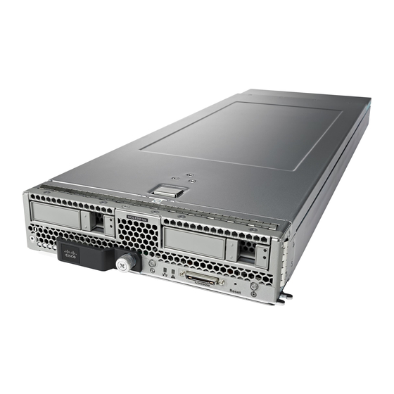
Page 10: External Features Overview
The removable drives also have LEDs indicating hard disk access activity and disk health. Cisco UCS B200 M4 Blade Server Installation and Service Note... - Page 11 Activity Inactive. (Disk Drive) Green Outstanding I/O to disk drive. Flashing Green Rebuild in progress. Health LED will flash in unison. 4 Hz Flashing Green Identify drive active. 4 hz Cisco UCS B200 M4 Blade Server Installation and Service Note...
-
Page 12: Buttons
To safely reboot a server from a power-down state, use the Boot Server action in Cisco UCS Manager. -
Page 13: Secure Digital Cards
Storage Module The Cisco UCS B200 M4 blade server has an optional storage module that can be configured with SAS or SATA hard drives or solid state disks (SSDs). Because the UCS B200 M4 can be used without disk drives,... -
Page 14: Cisco Ucs B200 M4 Blade Server Installation And Service Note
A pair of blanking panels (two with this product ID: UCSB-LSTOR-BK) may be in place on a new UCS B200 M4 blade server. For information on installing the storage module, see... -
Page 15: Installing A Blade Server
Installing a Half-width Blade Server UCS B200 M4, UCS B200 M3, and UCS B22 M3 half-width blade servers are interoperable in a UCS chassis with any other UCS blade servers, including prior generation B200 M2 and B200 M1 servers, or other UCS B-Series blade servers. - Page 16 Step 6 Power on the server. UCS Manager automatically reacknowledges, reassociates, and recommissions the server, provided any hardware changes are allowed by the service profile. Cisco UCS B200 M4 Blade Server Installation and Service Note...
-
Page 17: Server Configuration
Server Configuration Server Configuration Cisco UCS blade servers should be configured and managed using Cisco UCS Manager. For details, see the Configuration Guide for the version of Cisco UCS Manager that you are using. The configuration guides are available at the following URL: http://www.cisco.com/en/US/products/ps10281/products_installation_and_... -
Page 18: Server Troubleshooting
If the slot is to remain empty, install a blank faceplate (N20-CBLKB1) to keep dust out of the chassis. Server Troubleshooting For general troubleshooting information, see the see the Cisco UCS Manager B-Series Troubleshooting Guide. Cisco UCS B200 M4 Blade Server Installation and Service Note... -
Page 19: Servicing A Blade Server
The modular storage system has two front-accessible drive bays that support hot-swappable, 2.5 inch drives. If you purchased the UCS B200 M4 blade server without the modular storage system configured as a part of the system, a pair of blanking panels may be in place. These panels should be removed before installing hard drives, but should remain in place to ensure proper cooling and ventilation if the drive bays are unused. -
Page 20: Removing A Blade Server Hard Drive
Removing a Blade Server Hard Drive Before upgrading or adding a drive to a running system, check the service profile in Cisco UCS Manager and make sure the new hardware configuration will be within the parameters allowed by the service profile. -
Page 21: Removing A Blade Server Cover
Push the hard drive lever into the closed position. You can use Cisco UCS Manager to format and configure RAID services. For details, see the Configuration Guide for the version of Cisco UCS Manager that you are using. The configuration guides are available at the following URL: http://www.cisco.com/en/US/products/ps10281/products_installation_and_configuration_... -
Page 22: Air Baffles
B200 M4 server. No tools are necessary to install them, just place them over the DIMMs as shown, with the holes in the center of the baffles aligned with the corresponding motherboard standoffs. Figure 7: Cisco UCS B200 M4 Air Baffles Cisco UCS B200 M4 Blade Server Installation and Service Note... -
Page 23: Internal Components
Servicing a Blade Server Internal Components Internal Components Figure 8: Inside View of the UCS B200 M4 Blade Server SD card slots Modular storage subsystem connector USB connector DIMM slots An internal USB 2.0 port is supported. A 16 GB USB drive (UCS-USBFLSHB-16GB) is available from Cisco. -
Page 24: Diagnostics Button And Leds
Installing a CMOS Battery All Cisco UCS blade servers use a CR2032 battery to preserve BIOS settings while the server is not installed in a powered-on chassis. Cisco supports the industry standard CR2032 battery that is available at most electronics stores. - Page 25 Servicing a Blade Server Installing a CMOS Battery d) Replace the server in the chassis and power on the blade by pressing the Power button. Figure 9: Location of the Motherboard CMOS Battery Cisco UCS B200 M4 Blade Server Installation and Service Note...
-
Page 26: Installing The Storage Module
Figure 10: Storage Module Step 3 Using a Phillips-head screwdriver, tighten the four screws to secure the storage module. The locations of the screws are labeled "Secure Here." Cisco UCS B200 M4 Blade Server Installation and Service Note... -
Page 27: Removing A Heat Sink And Cpu
Removing a Heat Sink and CPU Removing a Heat Sink and CPU Procedure Step 1 Unscrew the four captive screws. Step 2 Remove the heat sink. Figure 11: Removing the Heat Sink and CPU Cisco UCS B200 M4 Blade Server Installation and Service Note... -
Page 28: Installing A New Cpu And Heat Sink
• A BIOS update is available and installed that supports the CPU and the given server configuration. • If the server will be managed by Cisco UCS Manager, the service profile for this server in Cisco UCS Manager will recognize and allow the new CPU. - Page 29 Hold the CPU carrier by its sides (indicated b the arrows). Insert and align the two CPU carrier pegs into the self-loading socket (SLS) plug seat. To ensure proper seating, verify that the horizontal yellow line below the word ALIGN is straight. Figure 13: Inserting the CPU Carrier Cisco UCS B200 M4 Blade Server Installation and Service Note...
-
Page 30: Installing Memory
Press the DIMM into its slot evenly on both ends until it clicks into place. DIMMs are keyed. If a gentle force is not sufficient, make sure the notch on the DIMM is correctly aligned. Cisco UCS B200 M4 Blade Server Installation and Service Note... -
Page 31: Supported Dimms
Each channel is identified by a letter—A, B, C, D for CPU1, and E, F, G, H for CPU 2. Each DIMM slot is numbered 1, 2, or 3. Note that each DIMM slot 1 is blue, each slot 2 is black, and each slot 3 is off-white or beige. Cisco UCS B200 M4 Blade Server Installation and Service Note... - Page 32 CPU (CPU shown on right in the diagram), while the DIMM slots in the upper and lower left are associated with the first CPU (CPU shown on left). Figure 16: Physical Representation of DIMMs and Channels Cisco UCS B200 M4 Blade Server Installation and Service Note...
- Page 33 Channel (2DPC) configuration, or a three DIMMs per Channel (3DPC) configuration. Each CPU in a Cisco UCS B200 M4 blade server supports four channels of three memory slots each. In a 1 DPC configuration, DIMMs are in slot 1 only. In a 2 DPC configuration, DIMMs are in both slot 1 and slot 2.
-
Page 34: Memory Performance
• DIMMs can be run in a 1DPC, a 2DPC, or a 3DPC configuration. 1 DPC and 2DPC can provide the maximum rated speed that the CPU and DIMMs are rated for. 3DPC causes the DIMMs to run at a slower speed. Cisco UCS B200 M4 Blade Server Installation and Service Note... -
Page 35: Memory Mirroring And Ras
They provide connectivity through Cisco UCS 6100 and 6200 Series Fabric Interconnects. The Cisco VIC 1200 Series (1240 and 1280) is compatible in UCS domains that implement both UCS 6100 and 6200 Series Fabric Interconnects. However, the Cisco VIC 1300 Series (1340 and 1380) is compatible only with the UCS 6200 Series Fabric Interconnects. -
Page 36: Installing An Adapter Card
URL: http://www.cisco.com/en/US/products/ps10280/products_data_sheets_list.html The UCS B200 M4 blade server has two adapter slots (Slots 1 and 2) that support the following VIC cards: • VIC 1340 and VIC 1380 • VIC 1240 and VIC 1280 Slot 1 is for the VIC 1340 or VIC 1240 cards. - Page 37 The Cisco Fusion-io Drive mezzanine and other non-IO adapter cards can be installed and removed using the same procedures. Using these cards in a UCS B200 M4 blade server requires the presence of a VIC 1340 or VIC 1240 mLOM to provide blade I/O. They will not work in M1 and M2 Cisco UCS servers.
- Page 38 Removing an adapter card is the reverse of installing it. You might find it helpful when removing the connector from the motherboard to gently rock the board along the length of the connector until it loosens. Figure 19: Installing an Adapter Card Cisco UCS B200 M4 Blade Server Installation and Service Note...
-
Page 39: Installing The Nvidia M6 Gpu
2 when the nVidia M6 GPU is installed. • Upgrade your Cisco UCS system to a version of Cisco UCS Manager that supports this card. Refer to the latest version of the Release Notes for Cisco UCS Software at the following URL for information... - Page 40 Servicing a Blade Server Installing the nVidia M6 GPU about supported hardware: http://www.cisco.com/c/en/us/support/servers-unified-computing/ucs-manager/ products-release-notes-list.html. Cisco UCS B200 M4 Blade Server Installation and Service Note...
- Page 41 Position the GPU over the connector on the motherboard and align all captive screws to the standoff posts (callout 1). Step 4 Tighten the captive screws (callout 2). Figure 21: Installing the nVidia M6 GPU Cisco UCS B200 M4 Blade Server Installation and Service Note...
-
Page 42: Enabling The Trusted Platform Module
TPM. Procedure Step 1 Install the TPM hardware. a) Power off, decommission, and remove the blade server from the chassis. b) Remove the blade server cover. Cisco UCS B200 M4 Blade Server Installation and Service Note... - Page 43 TPM support is enabled by default in Cisco UCS Manager Release 2.2(4) and later BIOS policy. If your Cisco UCS Manager Release 2.2(4) and later BIOS policy is using the default and TPM support is already enabled, skip this procedure and go to the next step.
- Page 44 Intel TXT provides for a sealed portion of storage where sensitive data such as encryption keys can be kept, helping to shield them from being compromised during an attack by malicious code. a) In the Cisco UCS Manager Navigation pane, click the Servers tab. b) On the Servers tab, expand Servers > Policies.
-
Page 45: Technical Specifications
C H A P T E R Technical Specifications This chapter contains the following section: • Physical Specifications for the Cisco UCS B200 M4 Blade Server, page 37 Physical Specifications for the Cisco UCS B200 M4 Blade Server Specification Value Height 1.95 inches (50 mm) - Page 46 Technical Specifications Physical Specifications for the Cisco UCS B200 M4 Blade Server Cisco UCS B200 M4 Blade Server Installation and Service Note...