Cisco UCS B200 M4 Installation And Service Note
Blade server
Hide thumbs
Also See for UCS B200 M4:
- Installation and service note (46 pages) ,
- Upgrade manual (9 pages) ,
- Servicing manual (24 pages)

Related Manuals for Cisco UCS B200 M4


Summary of Contents for Cisco UCS B200 M4
-
Page 1: Table Of Contents
Cisco UCS B200 M4 Blade Server Installation and Service Note Cisco UCS B200 M4 Blade Server LEDs Buttons Connectors Secure Digital (SD) Card Access Storage Module Removing a Blade Server Cover Installing the Storage Module Hard Drive Replacement Blade Server Removal and Installation... -
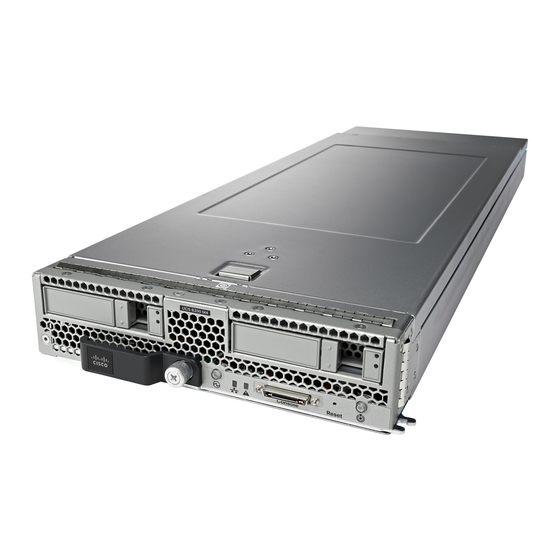
Page 2: Cisco Ucs B200 M4 Blade Server
CPUs and up to 24 DDR4 DIMMs. It supports one modular LOM (dedicated slot for Cisco's Virtual Interface Card) and one mezzanine adapter. In addition, the UCS B200 M4 supports an optional storage module that supports up to 2 SAS or SATA hard drives or solid state disks (SSDs) . - Page 3 Table 1: Blade Server LEDs Color Description Power Power off. Green Normal operation. Amber Standby. Link None of the network links are up. Green At least one network link is up. Health Power off. Green Normal operation. Amber Minor error. Blinking Critical error.
-
Page 4: Buttons
If the desired power state for a service profile associated with a blade server or an integrated rack-mount server is set to "off", using the power button or Cisco UCS Manager to reset the server will cause the desired power state of the server to become out of sync with the actual power state and the server may unexpected shutdown at a later time. -
Page 5: Storage Module
Storage Module The Cisco UCS B200 M4 blade server has an optional storage module that can be configured with SAS or SATA hard drives or solid state disks (SSDs). Because the UCS B200 M4 can be used without disk drives, it does not necessarily come with the storage module installed. - Page 6 Step 1 Press and hold the button down as shown in the figure below. Step 2 While holding the back end of the cover, pull the cover back and then up. Figure 4: Opening a Cisco UCS B200 M4 Blade Server...
-
Page 7: Installing The Storage Module
You can remove and install blade server hard drives without removing the blade server from the chassis. The drives supported in this blade server come with the drive sled attached. Spare drive sleds are not available. A list of currently supported drives is in the specification sheets at: http://www.cisco.com/en/US/products/ps10280/products_data_sheets_list.html... - Page 8 Before upgrading or adding an HDD to a running system, check the service profile in Cisco UCS Manager and make sure the new hardware configuration will be within the parameters allowed by the service profile. Caution To prevent ESD damage, wear grounding wrist straps during these procedures and handle modules by the carrier edges only.
-
Page 9: Blade Server Removal And Installation
You can use Cisco UCS Manager to format and configure RAID services. For details, see the Configuration Guide for the version of Cisco UCS Manager that you are using. The configuration guides are available at the following URL: http:// www.cisco.com/en/US/products/ps10281/products_installation_and_configuration_guides_list.html... - Page 10 Installing a Half-width Blade Server UCS B200 M4, UCS B200 M3, and UCS B22 M3 half-width blade servers are interoperable in a UCS chassis with any other UCS blade servers, including prior generation B200 M2 and B200 M1 servers, or other UCS B-Series blade servers. To install a half-width...
- Page 11 Procedure Step 1 Grasp the front of the blade server and place your other hand under the blade to support it. Figure 7: Positioning a Blade Server in the Chassis Step 2 Open the ejector lever in the front of the blade server. Step 3 Gently slide the blade into the opening until you cannot push it any farther.
-
Page 12: Internal Components
Internal Components Figure 8: Inside View of the UCS B200 M4 Blade Server SD card slots Modular storage subsystem connector USB connector DIMM slots An internal USB 2.0 port is supported. A 16 GB USB drive (UCS-USBFLSHB-16GB) is available from Cisco. A clearance of 0.950 inches (24.1 mm) is required for the USB... -
Page 13: Air Baffles
DIMMs as shown, with the holes in the center of the baffles aligned with the corresponding motherboard standoffs. Figure 9: Cisco UCS B200 M3 Air Baffles Diagnostics Button and LEDs At blade start-up, POST diagnostics test the CPUs, DIMMs, HDDs, and adapter cards, and any failure notifications are sent to UCS Manager. -
Page 14: Working Inside The Blade Server
Working Inside the Blade Server Installing a Motherboard CMOS Battery All Cisco UCS blade servers use a CR2032 battery (Cisco PID N20-MBLIBATT=) to preserve BIOS settings while the server is powered down. Warning There is danger of explosion if the battery is replaced incorrectly. - Page 15 d) Replace the server in the chassis and power on the blade by pressing the Power button. Figure 10: Location of the Motherboard CMOS Battery...
- Page 16 CPU and Heatsink Replacement Removing a Heat Sink and CPU Procedure Step 1 Unscrew the four captive screws. Step 2 Remove the heat sink. Figure 11: Removing the Heat Sink and CPU...
- Page 17 • A BIOS update is available and installed that supports the CPU and the given server configuration. • If the server will be managed by Cisco UCS Manager, the service profile for this server in Cisco UCS Manager will recognize and allow the new CPU.
- Page 18 Procedure Step 1 Hold the CPU carrier by its sides (indicated b the arrows). Insert and align the two CPU carrier pegs into the self-loading socket (SLS) plug seat. To ensure proper seating, verify that the horizontal yellow line below the word ALIGN is straight. Figure 13: Inserting the CPU Carrier...
- Page 19 Step 2 Press gently on the top of the CPU carrier from the exterior side until it snaps into place. Step 3 Close the socket latch. Step 4 Hook the self-loading socket (SLS) lever . Step 5 Hook the SLS lever Step 6 Thermally bond the CPU and heat sink using the thermal grease provided.
- Page 20 The DIMMs supported in this blade server are constantly being updated. A list of currently supported and available DIMMs is in the specification sheets at: http://www.cisco.com/en/US/products/ps10280/products_data_sheets_list.html Cisco does not support third-party memory DIMMs, and in some cases their use may irreparably damage the server and require an RMA and down time.
- Page 21 Memory Arrangement The blade server contains 24 DIMM slots—12 for each CPU. Each set of 12 DIMM slots is arranged into four channels, where each channel has three DIMMs. Figure 16: Memory Slots In the Blade Server Channels A-D for CPU 1 Channels E-H for CPU 2 DIMMs and Channels Each channel is identified by a letter—A, B, C, D for CPU1, and E, F, G, H for CPU 2.
- Page 22 DIMMs per Channel (3DPC) configuration. Each CPU in a Cisco UCS B200 M4 blade server supports four channels of three memory slots each. In a 1 DPC configuration, DIMMs are in slot 1 only. In a 2 DPC configuration, DIMMs are in both slot 1 and slot 2. In a 3 DPC configuration, DIMMs are in...
- Page 23 Table 2: Supported DIMM Population Order DIMMs per CPU CPU 1 installed slots CPU 2 installed slots A1, B1 E1, F1 A1, B1, C1 E1, F1, G1 4 (Blue slots) A1, B1, C1, D1 E1, F1, G1, H1 A1, B1, C1, D1, A2 E1, F1, G1, H1, E2 A1, B1, C1, D1, A2, B2 E1, F1, G1, H1, E2, F2...
- Page 24 Installing a mLOM Adapter The Cisco VIC 1340 and VIC 1240 are specialized modular LAN on Motherboard (mLOM) adapters that provide dual 2 x 10 Gb of Ethernet/ or Fiber Channel over Ethernet (FCoE) connectivity to each chassis. They plug into the dedicated mLOM connector only, and they are the only adapters that can be plugged into the mLOM connector.
-
Page 25: Installing An Adapter Card
Slot 1 is for the VIC 1340 or VIC 1240 cards. Slot 2 is for the VIC 1380 and VIC 1280 cards, and can also be used for the VIC port expander, third-party CNA cards, and non-I/O mezzanine cards, such as Fusion IO. The VIC 1340 and VIC 1380 require a Cisco UCS 6200 Series Fabric Interconnect, and they support the Cisco Nexus 2208XP and 2204XP Fabric Extender (FEX) modules. -
Page 26: Enabling A Trusted Platform Module
Enabling a Trusted Platform Module The Trusted Platform Module (TPM, Cisco Product ID UCSX-TPM2-001) is a component that can securely store artifacts used to authenticate the server. These artifacts can include passwords, certificates, or encryption keys. A TPM can also be used to store platform measurements that help ensure that the platform remains trustworthy. -
Page 27: Server Troubleshooting
Cisco UCS blade servers are intended to be configured and managed using Cisco UCS Manager. For details, see the Configuration Guide for the version of Cisco UCS Manager that you are using. The configuration guides are available at the following URL: http:/ /www.cisco.com/en/US/products/ps10281/products_installation_and_configuration_guides_list.html... -
Page 28: Obtaining Documentation And Submitting A Service Request
Documentation, which also lists all new and revised Cisco technical documentation. Subscribe to the What's New in Cisco Product Documentation as a Really Simple Syndication (RSS) feed and set content to be delivered directly to your desktop using a reader application. The RSS feeds are a free service and Cisco currently supports RSS version 2.0. - Page 29 Cisco and the Cisco logo are trademarks or registered trademarks of Cisco and/or its affiliates in the U.S. and other countries. To view a list of Cisco trademarks, go to this URL: www.cisco.com/go/trademarks . Third-party trademarks mentioned are the property of their respective owners. The use of the word partner does not imply a partnership relationship between Cisco and any other company.
- Page 30 Cisco Systems, Inc. Cisco Systems (USA) Pte. Ltd. Cisco Systems International BV San Jose, CA 95134-1706 Singapore Amsterdam, The Netherlands Cisco has more than 200 offices worldwide. Addresses, phone numbers, and fax numbers are listed on the Cisco Website at www.cisco.com/go/offices.