Cisco UCS B200 M3 Installation Manual
Blade server
Hide thumbs
Also See for UCS B200 M3:
- Spec sheet (64 pages) ,
- Installation and service note (37 pages) ,
- Upgrade manual (21 pages)

Related Manuals for Cisco UCS B200 M3


Summary of Contents for Cisco UCS B200 M3
-
Page 1: Table Of Contents
Cisco UCS B200 M3 Blade Server Installation and Service Note Cisco UCS B200 M3 Blade Server LEDs Buttons Connectors Hard Drive Replacement Blade Server Removal and Installation Secure Digital (SD) Card Access Removing a Blade Server Cover Working Inside the Blade Server... -
Page 2: Cisco Ucs B200 M3 Blade Server
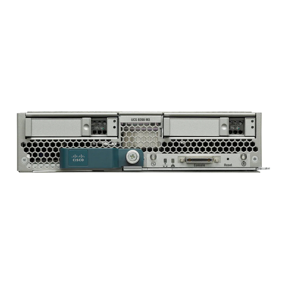
Cisco UCS B200 M3 Blade Server The Cisco UCS B200 M3 is an Intel-based, half-width blade supporting two CPU sockets using Intel E5-2600 series CPUs and up to 24 DIMMs; it supports one modular LOM (dedicated slot for Cisco's Virtual Interface Card) and one mezzanine adapter. At this time, the UCS B200 M2 (second generation) server is still available and is documented elsewhere. - Page 3 Table 1: Blade Server LEDs Color Description Power Power off. Green Normal operation. Amber Standby. Link None of the network links are up. Green At least one network link is up. Health Power off. Green Normal operation. Amber Minor error. Blinking Critical error.
-
Page 4: Buttons
If the desired power state for a service profile associated with a blade server or an integrated rack-mount server is set to "off", using the power button or Cisco UCS Manager to reset the server will cause the desired power state of the server to become out of sync with the actual power state and the server may unexpected shutdown at a later time. - Page 5 Before upgrading or adding an HDD to a running system, check the service profile in Cisco UCS Manager and make sure the new hardware configuration will be within the parameters allowed by the service profile. Caution To prevent ESD damage, wear grounding wrist straps during these procedures and handle modules by the carrier edges only.
-
Page 6: Blade Server Removal And Installation
Push the hard drive lever into the closed position. You can use Cisco UCS Manager to format and configure RAID services. For details, see the Configuration Guide for the version of Cisco UCS Manager that you are using. The configuration guides are available at the following URL: http:// www.cisco.com/en/US/products/ps10281/products_installation_and_configuration_guides_list.html... -
Page 7: Removing A Blade Server
Powering Off Blade Servers Using the Power Button You can also shut the server down remotely using Cisco UCS Manager. For details, see the Configuration Guide for the version of Cisco UCS Manager that you are using. The configuration guides are available at the following URL: http://www.cisco.com/en/US/products/ps10281/products_installation_and_... - Page 8 Installing a Half-width Blade Server UCS B200 M3 and UCS B22 M3 half-width blade servers are interoperable in a UCS chassis with any other UCS blade servers, including prior generation B200 M2 and B200 M1 servers, or other UCS B-Series blade servers. To install a half-width blade server,...
-
Page 9: Secure Digital (Sd) Card Access
Step 2 Open the ejector lever in the front of the blade server. Step 3 Gently slide the blade into the opening until you cannot push it any farther. Step 4 Press the ejector lever so that it catches the edge of the chassis and presses the blade server all the way in. Step 5 Tighten the captive screw on the front of the blade to no more than 3 in-lbs. - Page 10 Step 1 Press and hold the button down as shown in the figure below. Step 2 While holding the back end of the cover, pull the cover back and then up. Figure 7: Opening a Cisco UCS B200 M3 Blade Server...
-
Page 11: Air Baffles
The air baffles direct and improve air flow for the server components. Two identical baffles ship with each B200 M3 server. No tools are necessary to install them, just place them over the DIMMs as shown, with the holes in the center of the baffles aligned with the corresponding motherboard standoffs. Figure 8: Cisco UCS B200 M3 Air Baffles... -
Page 12: Internal Components
Figure 9: Inside View of the B200 M3 Blade Server Hard drive bays Internal USB connector Cisco UCS-USBFLSH-S-4GB= is recommended, but if another USB drive will be used it must be no wider than .8 inches, and no more than 1.345 inches long in order tp provide needed clearances to install or remove the USB drive. -
Page 13: Working Inside The Blade Server
Working Inside the Blade Server Installing a Motherboard CMOS Battery All Cisco UCS blade servers use a CR2032 battery (Cisco PID N20-MBLIBATT=) to preserve BIOS settings while the server is powered down. Warning There is danger of explosion if the battery is replaced incorrectly. - Page 14 d) Replace the server in the chassis and power on the blade by pressing the Power button. Figure 10: Location of the Motherboard CMOS Battery CPU and Heatsink Replacement Special Information For Upgrades to Intel E5-2600 v2 Series CPUs You must upgrade your server firmware to the required minimum level before you upgrade to Intel E5-2600 Caution v2 Series CPUs.
- Page 15 Do one of the following actions: • If your server’s firmware and/or Cisco UCS Manager software are already at the required levels shown in the table above, you can replace the CPU hardware by using the procedures in this section.
- Page 16 Step 3 Unhook the first socket hook, which has the following icon: See callout 3 in the following figure. Step 4 Unhook the second socket hook, which has the following icon: See callout 4 in the following figure. Step 5 Open the socket latch.
- Page 17 • A BIOS update is available and installed that supports the CPU and the given server configuration. • If the server will be managed by Cisco UCS Manager, the service profile for this server in Cisco UCS Manager will recognize and allow the new CPU.
- Page 18 Procedure Step 1 (Optional) If you are installing a CPU in a socket that had been shipped empty, there will be a protective cap intended to prevent bent or touched contact pins. The pick and pull cap tool provided can be used in a manner similar to a pair of tweezers.
- Page 19 e) Lift the tool and CPU straight up off of the pedestal. Figure 14: Loading the Pick and Place Tool Alignment mark on the pick and place tool, CPU and pedestal...
- Page 20 Step 4 Place the CPU and tool on the CPU socket with the registration marks aligned as shown. Step 5 Press the button/handle on the pick and place tool to release the CPU into the socket. Figure 15: Using the CPU Pick and Place Tool to Insert the CPU Alignment mark on the tool button/handle Alignment mark on the CPU socket...
- Page 21 Step 6 Close the socket latch. See callout 1 in the following figure. Step 7 Secure the first hook, which has the following icon: See callout 2 in the following figure. Step 8 Secure the second hook, which has the following icon: See callout 3 in the following figure.
- Page 22 Figure 17: Thermal Grease Application Pattern Step 10 Replace the heat sink. See callout 4. Caution On certain models, heat sinks are keyed to fit into the plastic baffle extending from the motherboard. Do not force a heat sink if it is not fitting well, rotate it and re-orient the heat sink. Step 11 Secure the heat sink to the motherboard by tightening the four captive screws a quarter turn at a time in an X pattern as shown in the upper right.
- Page 23 The DIMMs supported in this blade server are constantly being updated. A list of currently supported and available drives is in the specification sheets at: http://www.cisco.com/en/US/products/ps10280/products_data_sheets_list.html Cisco does not support third-party memory DIMMs, and in some cases their use may irreparably damage the server and require an RMA and down time.
- Page 24 Memory Arrangement The blade server contains 24 DIMM slots—12 for each CPU. Each set of 12 DIMM slots is arranged into four channels, where each channel has three DIMMs. Figure 19: Memory Slots within the Blade Server Channels A-D for CPU 1 Channels E-H for CPU 2 DIMMs and Channels Each channel is identified by a letter—A, B, C, D for CPU1, and E, F, G, H for CPU 2.
- Page 25 The figure below shows how DIMMs and channels are physically laid out on the blade server. The DIMM slots in the upper and lower right are associated with the second CPU (CPU shown on right in the diagram), while the DIMM slots in the upper and lower left are associated with the first CPU (CPU shown on left).
- Page 26 DIMMs per Channel (3DPC) configuration. Each CPU in a Cisco UCS B200 M3 blade server supports four channels of three memory slots each. In a 1 DPC configuration, DIMMs are in slot 0 only. In a 2 DPC configuration, DIMMs are in both slot 0 and slot 1. In a 3 DPC configuration, DIMMs are in...
- Page 27 Table 3: Supported DIMM Population Order DIMMs per CPU CPU 1 installed slots CPU 2 installed slots A0, B0 E0, F0 A0, B0, C0 E0, F0, G0 4 (Blue slots) A0, B0, C0, D0 E0, F0, G0, H0 A0, B0, C0, D0, A1 E0, F0, G0, H0, E1 A0, B0, C0, D0, A1, B1 E0, F0, G0, H0, E1, F1...
- Page 28 Installing a Modular LOM The Cisco VIC 1240 is a specialized modular Lan on Motherboard (mLOM) adapter that provides dual 2 x 10 Gb of Ethernet/ or Fiber Channel over Ethernet (FCoE) connectivity to each chassis. It plugs into the dedicated mLOM connector only. It is currently the only card that can be plugged into the mLOM connector and it will provide connectivity through either a 2100 series or 2200 series IOM.
-
Page 29: Installing An Adapter Card
Using these drives in a B200 M3 or B22 M3 blade server requires the presence of a VIC 1240 mLOM to provide blade I/O. They will not work in M1 and M2 generation Cisco UCS servers. These drives appear in Cisco UCS Manager as regular SSDs. -
Page 30: Enabling A Trusted Platform Module
Enabling a Trusted Platform Module The Trusted Platform Module (TPM, Cisco Product ID UCSX-TPM1-001) is a component that can securely store artifacts used to authenticate the server. These artifacts can include passwords, certificates, or encryption keys. A TPM can also be used to store platform measurements that help ensure that the platform remains trustworthy. -
Page 31: Server Troubleshooting
Cisco UCS blade servers are intended to be configured and managed using Cisco UCS Manager. For details, see the Configuration Guide for the version of Cisco UCS Manager that you are using. The configuration guides are available at the following URL: http:/ /www.cisco.com/en/US/products/ps10281/products_installation_and_configuration_guides_list.html... -
Page 32: Obtaining Documentation And Submitting A Service Request
Documentation, which also lists all new and revised Cisco technical documentation. Subscribe to the What's New in Cisco Product Documentation as a Really Simple Syndication (RSS) feed and set content to be delivered directly to your desktop using a reader application. The RSS feeds are a free service and Cisco currently supports RSS version 2.0. - Page 33 Cisco and the Cisco logo are trademarks or registered trademarks of Cisco and/or its affiliates in the U.S. and other countries. To view a list of Cisco trademarks, go to this URL: www.cisco.com/go/trademarks . Third-party trademarks mentioned are the property of their respective owners. The use of the word partner does not imply a partnership relationship between Cisco and any other company.
- Page 34 Cisco Systems, Inc. Cisco Systems (USA) Pte. Ltd. Cisco Systems International BV San Jose, CA 95134-1706 Singapore Amsterdam, The Netherlands Cisco has more than 200 offices worldwide. Addresses, phone numbers, and fax numbers are listed on the Cisco Website at www.cisco.com/go/offices.