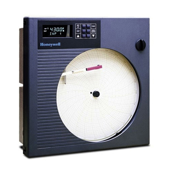
Honeywell DR4300 Replacement Instructions Manual
Circular chart recorder
Hide thumbs
Also See for DR4300:
- Product manual (266 pages) ,
- Getting started (2 pages) ,
- Kit instructions (5 pages)
Advertisement
Quick Links
Model DR4300/DR4500 Circular Chart Recorder
1.1 Summary
Document Number
Form: 43-DR-33-87
Effective: 3/05
Table of Contents
This instruction contains Servo Motor replacement instructions for the model numbers listed below:
1.2
1.3
1.4
1.5
DR45AH, DR45AP Truline Recorder
1.6
1.7
Symbol Definitions
WARNING
3/05
Replacement Instruction
Servo Motor Kit (30756114-501)
Topic
WARNING
PERSONAL INJURY: Risk of electrical shock. This symbol warns the user of a
potential shock hazard where HAZARDOUS LIVE voltages greater than 30 Vrms,
42.4 Vpeak, or 60 Vdc may be accessible. Failure to comply with these
instructions could result in death or serious injury.
ATTENTION, Electrostatic Discharge (ESD) hazards. Observe precautions for
handling electrostatic sensitive devices.
Never access components inside the controller enclosure with power applied.
Replacement Kit Instruction 43-DR-33-87
See Page
2
3
6
9
12
16
1
Advertisement

Related Manuals for Honeywell DR4300


Summary of Contents for Honeywell DR4300
-
Page 1: Table Of Contents
Model DR4300/DR4500 Circular Chart Recorder Replacement Instruction Servo Motor Kit (30756114-501) 1.1 Summary Document Number Form: 43-DR-33-87 Effective: 3/05 Table of Contents This instruction contains Servo Motor replacement instructions for the model numbers listed below: Topic See Page DR4501, DR45A1 - One Pen Classic Servo Motor Replacement... -
Page 2: Dr4501, Dr45A1 - One Pen Classic Servo Motor Replacement
1.2 DR4501, DR45A1 - One Pen Classic Servo Motor Replacement Introduction The procedure in Table 1 lists the steps required to replace the Servo Motor assembly in Models DR4501, and DR45A1, One Pen Classic Models of the DR4500/DR4500A Circular Chart Recorders. -
Page 3: Dr4501, Dr45A1 - One Pen Classic Pen Alignment
1.3 DR4501, DR45A1 - One Pen Classic Pen Alignment Mechanical Alignment CAUTION Align the pen mechanically as shown in Table 2 and then electrically as described in Table 3. Never attempt to manually force the pen arms from the front, since this will damage the pen mechanism. - Page 4 Electrical Alignment If the group prompt “LOCKOUT” has been configured for “CALIB”, +VIEW”, or “MAX” selection, you will not be able to access PEN 1 group prompt for electrical alignment. Set LOCKOUT to “NONE”. Table 3 Procedure for Setting the Chart Time Line Step Press Action/Result...
- Page 5 Table 3 - continued Step Press Action/Result You will see: LOWR Upper Display DISP ALIGN Lower Display PEN 1 0 0 The value adjusted in step 3 is entered into memory. to raise or lower the value in the upper display (up to 1200) move the pen to the highest chart range value (outer circumference printed on the chart).
-
Page 6: Dr4502, Dr45A2 - Two Pen Classic Servo Motor Replacement
1.4 DR4502, DR45A2 - Two Pen Classic Servo Motor Replacement Introduction The procedure in Table 4 lists the steps required to replace the #2 Servo Motor assembly in Models DR4502, and DR45A2, Two Pen Classic Models of the DR4500/DR4500A Circular Chart Recorders. - Page 7 9 position keyboard cable 2 wires (black) Pen 1 30755064-001, 20 conductor ribbon cable Motor Display board Pen 2 Motor Chassis ground 4 conductor cable 4 conductor cable 4 conductor cable Pen #1 drive Chart motor Pen #2 drive Chart drive Chart Plate Password Light...
- Page 8 9 position keyboard cable Light line to J1 Pen 1 30755064-001, 20 conductor ribbon cable Motor Display board Pen 2 Chassis ground Motor 30755062-001 4 conductor cable 4 conductor cable 4 conductor cable Chart motor Pen #1 drive Pen #2 drive Chart Plate Chart drive 2 wire...
-
Page 9: Dr450T, Dr450R, Dr450W, Dr45At, Dr45Ar, Dr45Aw
1.5 DR450T, DR450R, DR450W, DR45AT, DR45AR, DR45AW, DR45AH, DR45AP Truline Recorder Introduction The procedure in Table 5 lists the steps required to replace the Servo Motor assembly in Models DR450T, DR450R, DR450W, DR45AT, DR45AR, DR45AW, DR45AH, DR45AP Truline Recorder The procedure assumes that the chart door is opened, the chart plate is swung out, and that the power is removed. - Page 10 Optical sensor 9 position keyboard cable assembly Light line to J1 2 wires (black) 30755064-001, 20 conductor ribbon cable Display board Chassis ground Motor 30754982-001 4 conductor cable 4 conductor cable stylus 4 conductor cable Optical sensor Chart motor Pen drive Chart drive Chart Plate 2 wire...
- Page 11 Optical sensor Pen stylus assembly 9 position keyboard cable 2 wires (black) 30755064-001, 20 conductor ribbon cable Display board Motor Chassis ground 4 conductor cable 4 conductor cable 4 conductor cable Optical sensor Chart motor Pen drive Chart drive Chart Plate Password Light jumper...
-
Page 12: Dr4300 Recorder One Pen Models
The procedure assumes that the chart door is opened, the chart plate is swung out, and that the power is removed. Table 6 Procedure for Replacing the Servo Motor on a One Pen DR4300 Step Action Power down the recorder and open the chart door. - Page 13 Pen Alignment – Recorder without Display Table 7 gives the procedure for aligning pens at the zero and 100% chart positions in a recorder without a display. Refer to Figure 6 for location of switches. Table 7 Procedure for Pen Alignment (Recorder without Display) Step Action Place the run/setup switch SW5 to the setup position (toward the top of the board) on...
- Page 14 LOWER RAISE S2 = Reset S3 = Lower S4 = Raise SETUP Run/Setup Switch 24239 Figure 6 Location of Switches Replacement Kit Instruction 43-DR-33-87 3/05...
- Page 15 Procedure for Pen Alignment (Recorder with Display) Table 8 gives the procedure for aligning pens at zero and span (full scale) in a recorder with a display. Table 8 Procedure for Pen Alignment (Recorder with Display) Step Press Action/Result until you can see: Upper Display ALIN Lower Display...
-
Page 16: Dr4300 Recorder Two Pen Models
The procedure assumes that the chart door is opened, the chart plate is swung out, and that the power is removed. Table 9 Procedure for Replacing the Servo Motor on a Two Pen DR4300 Step Action Refer to Figure 7 for the location of the #2 Pen Motor. - Page 18 However, we assume no responsibility for its use. While we provide application assistance personally, through our literature and the Honeywell web site, it is up to the customer to determine the suitability of the product in the application Honeywell International, Inc...