Honeywell X Series Installation Instruction Sheet
Backlight replacement
Hide thumbs
Also See for X Series:
- User manual (325 pages) ,
- Installation instruction (5 pages) ,
- Manual (8 pages)
Advertisement
Quick Links
QX and SX Recorder - Installation Instruction
Backlight Replacement (For X Series Only)
QX Recorder
This Installation Instruction sheet is intended as a guide for replacing or installing hardware and for setting up
functionality in the recorder. Refer to the User manual for detailed operational requirements.
The QX and SX Recorders are designed for ease of assembly with minimal disturbance to the rest of the unit. If unsure,
please return the unit to your supplier for repair or upgrade.
Removing the case and opening the back of the recorder should only be performed under the following circumstances:
When an item of hardware requires individual replacement.
When an item of hardware is to be retrospectively fitted.
In all other instances it is recommended that the complete unit be returned to an authorised agent or service centre.
For Agency Approved recorders the product needs to be upgraded or repaired by an Authorized Repair facility
WARNING
HAZARDOUS VOLTAGES
Disconnect all power to the recorder before removing the case and attempting any maintenance procedures.
SAFETY TESTS
Upon completion of service procedures detailed in this manual two basic safety tests should be performed in order to
ensure continued safe operation of the instrument.
Earth Resistance; 25 VDC applied between case and protective earth, bonding resistance should be < 0.1 Ohm.
Insulation Resistance; 500Vdc applied between the earth terminal, and the live and neutral terminal shorted together,
insulation resistance to be >2.0 MOhm. (Mega Ohm, NOT milli Ohm)
Failure to comply with these instructions could result in death or serious injury
CAUTION
OBSERVE ANTI-STATIC PRECAUTIONS
Refer to BS EN61340-5-1: 2001. Basic specification. Protection of electrostatic sensitive devices.
Full anti-static precautions MUST be observed when in contact with the electronics of your recorder.
SAVE DATA, SETUPS AND LAYOUTS
Removal of PCBs and battery back-up will result in the loss of all non-volatile data.
Ensure all data and set-ups are saved.
Failure to comply with these instructions may result in product damage.
43-TV-33-76 iss.2 GLO Jan 21 UK
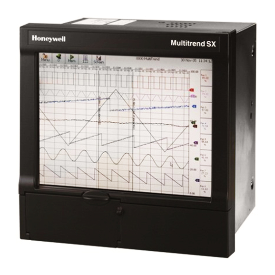
SX Recorder
1
Advertisement

Related Manuals for Honeywell X Series


Summary of Contents for Honeywell X Series
- Page 1 QX and SX Recorder - Installation Instruction Backlight Replacement (For X Series Only) QX Recorder SX Recorder This Installation Instruction sheet is intended as a guide for replacing or installing hardware and for setting up functionality in the recorder. Refer to the User manual for detailed operational requirements.
-
Page 2: Panel Mounting
Before attempting to repair or upgrade a recorder, it is advisable to clear a sufficient work space so components such as the front panel can be rested on the work surface without getting scratched or damaged. Panel Mounting Before a new backlight can be fitted the recorder must be removed from the panel. Loosen the mounting clamp screws, slide the clamp towards the rear of the recorder and remove the clamps and the recorder. - Page 3 Next disconnect the inverter high voltage cables by pulling upwards. See Fig 5. Fig 5 Inverter cable Remove the eight self tapping screws that fix the plastic bezel to the mounting plate. A screw driver with a long shaft will make this operation much easier.
- Page 4 Once the screws are removed the black plastic bezel and touch screen assembly can be folded down. The touch screen will still be connected so take care not to damage this lead. Fig 7 Fig 7 Four display mounting screws Touch screen cable To remove the display unscrew the four display fixing screws.
- Page 5 Where the inverter lead comes out of the display there is a clip that will release the backlight. See Fig 9. Fig 9 Clip Press the clip down and gently pull on the cable to withdraw the backlight assembly. See Fig 10 Fig 10 Once the backlight has been removed the new backlight assembly can be fitted.
- Page 6 Re-building the recorder Rebuilding the recorder is the reverse process. Offer up the display to the front of the unit, reconnect the display lead and feed the inverter cable through the rectangular hole in the mounting plate. Fit the 4 screws holding the display in place. Before refitting the bezel/touch screen assembly clean any dirt or marks form the back of the touch screen or display.
- Page 7 QX Recorder To fit a new backlight the case and back panel must be removed. The case and back panel can be removed as a single assembly. Remove the 2 screws on each side of the case as shown in Fig 11 below Fig 11 Remove 2 screws from each side of the case...
- Page 8 To remove the Front surround assembly four self tapping screws must be removed. See Fig 13 Once these have been removed the front surround assembly can be carefully drawn forward. Disconnect the speaker cable from the mother board. Disconnect the display cable, inverter cable and touch screen cable from the processor board.
- Page 9 To remove the front bezel and touch screen assembly there are 4 self tapping screws that need to be removed, see Fig 14. Two screws are at the top of the assembly, and two screws are fitted one from each side. When these are removed the display assembly can be separated.
- Page 10 There are 2 backlights on the QX recorder display. These should be changed as a pair. To get the backlights out use a small screwdriver to push back the clip as shown in Fig 16 and gently pull on the leads to withdraw the backlight from the display.
- Page 11 Re-building the recorder Rebuilding the recorder is the reverse process. Feed the backlight leads through the holes in the moulding, and re-connect to the inverter. Pull any loose cable through the holes. Before refitting the bezel/touch screen assembly clean any dirt or marks form the back of the touch screen or display. Use a lint free cloth to clean both parts, do not use any solvents.