
Related Manuals for GE IC695PNC001


Summary of Contents for GE IC695PNC001
- Page 1 Intelligent Platforms Programmable Control Products PACSystems* RX3i PROFINET Controller Manual, GFK-2571A December 2011...
- Page 2 Features may be described herein which are not present in all hardware and software systems. GE Intelligent Platforms assumes no obligation of notice to holders of this document with respect to changes subsequently made.
- Page 3 Contact Information If you purchased this product through an Authorized Channel Partner, please contact the seller directly. General Contact Information Online technical support and http://support.ge-ip.com GlobalCare Additional information http://www.ge-ip.com/ Solution Provider solutionprovider.ip@ge.com Technical Support If you have technical problems that cannot be resolved with the information in this manual, please contact us by telephone or email, or on the web at http://support.ge-ip.com...
-
Page 5: Table Of Contents
Contents Introduction ........................1-1 PROFINET Controller Description ..................1-2 PROFINET Controller Specifications ................1-3 Operating Range for Surrounding Air Temperature ............1-4 PROFINET Controller Module Controls and Indicators ............ 1-5 System Limits ........................1-8 Machine Edition Project Maximum Limits ................. 1-8 PROFINET Networks for PACSystems ................ - Page 6 Contents Diagnostics ........................5-1 Powerup and Reset ......................5-2 Special LED Blink Patterns ....................5-5 Status Reporting ....................... 5-6 Fault Contacts ........................5-7 Fault Locating References ....................5-7 Fatal Error Reporting ......................5-7 PROFINET IO Alarms ....................... 5-8 The PROFINET Controller’s Local Log Table ..............5-9 PROFINET Controller Faults in the RX3i Fault Tables ...........
-
Page 7: Introduction
Chapter Introduction This chapter introduces the PACSystems RX3i PROFINET system and describes the RX3i PROFINET Controller (PNC) module. The last two pages of this chapter are a glossary that summarizes many terms used in the manual. Chapter 2, Installation explains how to install a PNC, how to complete port connections, and how to update the module firmware. -
Page 8: Profinet Controller Description
PROFINET Controller Description The PACSystems RX3i PROFINET Controller module, IC695PNC001, connects a PACSystems RX3i controller to a PROFINET network. It enables the RX3i controller to communicate STATUS with IO-Devices on the network. The PNC provides all the functions, CONFIG services, and protocols required for certification as a PROFINET IO Version 2.2 IO Controller, running at both 100Mbps and 1Gbps. -
Page 9: Profinet Controller Specifications
PROFINET Controller Specifications PROFINET Support PROFINET Version 2.2 General Class A IO-Controller CPU Compatibility Requires CPU315 or CPU320, with firmware version 7.0 or higher. Power Requirements 3.3V: 0.5 A with no SFP devices installed 1.2 A maximum (2 SFP devices installed, 0.35 A per SFP device) 1.5 A maximum Operating Temperature Range 0 to 60°C maximum surrounding air temperature without a fan. -
Page 10: Operating Range For Surrounding Air Temperature
Operating Range for Surrounding Air Temperature 0 to 60°C surrounding air temperature under the following Baseline Installation installation: ▪ 12-slot panel mounted backplane ▪ Two PNC modules in adjacent slots per backplane ▪ 1 GB Fiber SFPs ▪ All four ports active The following installation exceptions are cumulative: Installation Exceptions Reduces maximum operating temperature:... -
Page 11: Profinet Controller Module Controls And Indicators
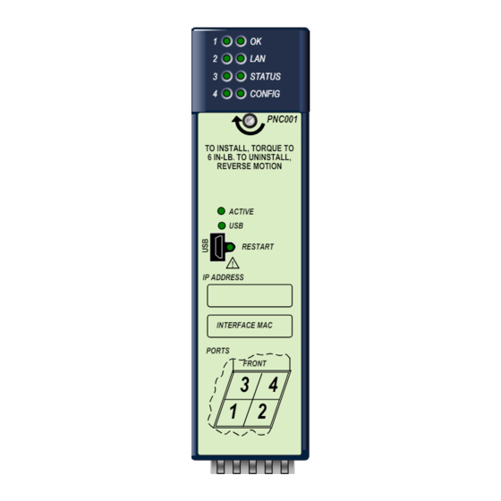
PROFINET Controller Module Controls and Indicators The illustration below shows the front of the RX3i PROFINET Controller module and identifies its controls and indicators. STATUS CONFIG LEDs: PNC001 1,2,3,4, OK, LAN, STATUS, CONFIG TO INSTALL, TORQUE TO 6 IN-LB. TO UNINSTALL, Heat sink screw REVERSE MOTION ACTIVE... - Page 12 2 – 500 2 – 550 2 – 10,000 1000BASE-LX 1300 2 – 70,000 1000BASE-ZX 1550 10/100/1000BASE-T CAT5/CAT5e/CAT6 100 (maximum) GE Intelligent Platforms part number IC695SPF002 GE Intelligent Platforms part number IC695SPC100 PACSystems* RX3i PROFINET Controller Manual – December 2011 GFK-2571A...
- Page 13 Micro USB Port The PROFINET Controller module has a micro USB port for connection to a computer running Windows 2000, Windows XP, Windows Vista, or Windows 7. The USB port can be used to access the PROFINET Controller’s Command Line Interface function using a terminal emulation application such as HyperTerminal.
-
Page 14: System Limits
System Limits 4 PROFINET Controller modules per RX3i CPU, connected to the same network or to separate networks. 128 IO-Devices on the PROFINET network. 8 IO-Controllers per network 64 IO-Devices per PROFINET Controller 128 IO-Devices per network, spread across a maximum of 8 IO-Controllers ... -
Page 15: Profinet Networks For Pacsystems
PROFINET Networks for PACSystems PROFINET is an open standard for industrial automation that is based on Industrial Ethernet. The PROFINET IO framework allows the creation of I/O data exchanges between controllers and distributed devices. It also allows configuration, parameterization, and diagnostics communication between controllers and devices. - Page 16 Basic System: One RX3i CPU and One PROFINET Controller using multiple ports The illustration below shows a basic system with one PACSystems RX3i CPU node that has one RX3i PROFINET Controller module controlling one PROFINET network. The network can connect up to 64 compatible IO-Devices, including any combination of VersaMax PROFINET Scanners and third-party IO-Devices.
- Page 17 Basic System: Third-Party Devices and PME Programmer Third-party IO Devices can be used with the RX3i PROFINET Controller if their manufacturer provides a GSDML file that can be imported into Proficy Machine Edition (PME). The GSDML file defines the characteristics of the IO-Device and its I/O modules. Importing a third-party IO-Device GSDML file and configuring third-party IO-Devices are described in chapter 3, and in the Proficy Machine Edition online help.
- Page 18 Systems with One RX3i CPU and Two PROFINET Controllers Both examples in this section show systems with one RX3i CPU that has two PROFINET Controller modules. The PROFINET network can serve up to 63 IO-Devices (ring topology) or 64 IO-Devices (in star topology).
- Page 19 In the following example, the two PROFINET Controllers are connected to separate networks. The maximum number of IO-Devices with multiple PROFINET Controllers in the same RX3i controller is 128. NOTE: Daisy-chain shown for clarity. A star or ring topology is preferred. RX3i CPU Node w/ two PNCs IO LAN 2...
- Page 20 One RX3i CPU with Four Controllers on Separate Networks This example shows a system with one RX3i CPU node containing the maximum of four RX3i PROFINET Controllers, with each PROFINET Controller connected to a different network. In this architecture, up to 128 IO-Devices are allowed, spread across the four networks. Up to 64 IO- Devices can be controlled by any given PROFINET Controller.
- Page 21 Two RX3i CPUs with Two PROFINET Networks and One Ethernet Network The example on this page shows two RX3i CPU nodes, each with one RX3i PROFINET Controller module and one RX3i Ethernet Transmitter Module (ETM). The PROFINET Controller modules are connected to separate networks (IO LAN1 and IO LAN 2 in the illustration).
-
Page 22: Glossary
Glossary Application Relationship. PROFINET term for a relationship that is established between an IO-Controller/Supervisor and IO-Device. For any data to be exchanged between an IO- Controller/Supervisor and a given IO-Device, an Application Relationship must be established. Within the Application Relationship, various Communication Relationships are then established for the different types of data to be exchanged. - Page 23 Glossary, continued Record Data Object. Services used to read and write structured data stored in a PROFINET IO-Device. Along with Send Clock determines the Update Period for a PROFINET cyclic data transfer Reduction between two devices (see IOCR). The Update Period equals the Reduction Ratio Ratio multiplied by the Send Clock time.
-
Page 25: Installation
Chapter Installation This chapter provides instructions for installing PACSystems RX3i PROFINET Controller modules. ▪ Pre-Installation check ▪ Removing the backplane knockout ▪ Module installation and removal ▪ Hot insertion and removal ▪ Port connections ▪ Installing SFP devices ▪ LED indications ▪... -
Page 26: Pre-Installation Check
As the consignee, it is your responsibility to register a claim with the carrier for damage incurred during shipment. However, GE Intelligent Platforms will fully cooperate with you, should such action be necessary. -
Page 27: Removing The Backplane Knockout
Removing the Backplane Knockout The PNC must be installed in the main (CPU) rack of the RX3i system, using a Universal Backplane such as IC695CHS007, CHS012 or CHS016. The back of the PNC has an exposed heat sink and backplane connector. Before inserting the module into the backplane, remove the plastic knockout in the slot where the module will be placed. -
Page 28: Module Installation
Module Installation ▪ RX3i rack power may be off or on (“hot insertion”, see page 2-5 for information). ▪ Holding the module firmly, align the module with the correct slot and connector. ▪ Engage the module’s rear pivot hook in the notch on the top of the backplane (1). -
Page 29: Hot Insertion And Removal
Hot Insertion and Removal Modules in a Universal Backplane can be installed or removed while power is applied to the system. This includes backplane power and field power supplied to the module. The PNC must be properly seated with the latch engaged and all pins connected within 2 seconds. For removal, the module must be completely disengaged within 2 seconds. -
Page 30: Ethernet Port Connections
Ethernet Port Connections Each port on an RX3i PNC operates independently, so devices that operate at different speeds and/or duplex modes may be attached to the ports. Each port automatically detects the attached cable and functions properly with either straight-through or crossover cables. Note: The PROFINET Controller operates only in autonegotiate mode. - Page 31 Installing SFP Devices SFP (Small Form-Factor Pluggable) devices can be installed in Port 3 and Port 4 of the PROFINET Controller. See chapter 1 for a list of supported SFP devices, media types and distances. The specific SFP module installed in each cage must be defined in the Proficy Machine Edition configuration of the PNC.
- Page 32 Removing SFP Devices Warning If the surrounding air operating temperature of the PNC module is greater than 40 °C, SFP devices could have operating temperatures over 70 °C (158 °F). Under these conditions, for your safety, do not use bare hands to remove an SFP device from the SFP cage.
-
Page 33: Powerup Led Patterns
Powerup LED Patterns At powerup, the LEDs show the blink patterns described below. The LEDs also blink diagnostic patterns for certain operating errors and for module identification. See “Chapter 5, Diagnostics” for a description of the special blink patterns. Step LED/ Blink pattern Description STATUS... - Page 34 Detailed LED Descriptions OK LED The OK LED indicates whether the module is able to perform normal operation. Green, ON Green, blink pattern Fatal error. Flashes once between error codes blinked on the OK Amber, blink pattern Fatal error Not OK LAN LED The LAN LED indicates access to and activity on the Ethernet network.
- Page 35 ACTIVE LED The active LED indicates the status of PROFINET connections. Green, ON All configured PROFINET devices have established PROFINET connections Green, blink pattern Fatal error. Flashes once between error codes blinked on the OK Amber, ON At least one configured PROFINET device has established a PROFINET connection, but other configured PROFINET devices are not configured No configured PROFINET Devices have established PROFINET...
-
Page 36: Installing The Usb Port Driver
Installing the USB Port Driver Set up use of the module’s USB port in either of these ways: 1. Run the provided driver-install application before connecting the computer’s USB port to the PNC’s USB port the first time. 2. With the provided installation files accessible on either a local or network drive, attach the PC USB port to the Rx3i IO LAN USB port. -
Page 37: Firmware Updates
Firmware Updates The Winloader utility is used to update the firmware on an RX3i PROFINET Controller. The current firmware version of the RX3i PROFINET Controller may be obtained using either the Proficy Machine Edition (PME) programmer (Online Commands->Show Status->Details), or the module’s Command Line Interface node command. -
Page 39: Configuration
Chapter Configuration This chapter explains how to configure an RX3i PROFINET Controller and its I/O devices in a PACSystems RX3i controller system. Additional information about RX3i configuration is available in other PACSystems documentation and in the Logic Developer online help. This chapter discusses the following topics: ▪... -
Page 40: Configuration Overview
Configuration Overview The Proficy Machine Edition PLC Logic Developer programmer is used to create and download the configuration for an RX3i PROFINET network and its devices. System Planning Device Ownership Note that all modules in an IO-Device must belong to the same PROFINET network, that is, they are all owned by the same PNC. - Page 41 Basic Configuration Steps The basic configuration steps, described in this chapter, are: In the hardware configuration, add a PNC to the RX3i main rack. This automatically creates a LAN for the PNC. Configure the parameters of the PNC itself. ...
-
Page 42: Configuration Tools
Configuration Tools Proficy Machine Edition is the primary tool used to configure an RX3i PROFINET network. In addition, certain parameters can be set from a computer through the PNC’s Command Line Interface. The Command Line Interface can be used to set the PNC’s non-volatile parameters, which are listed below. -
Page 43: Configuring An Rx3I Profinet Controller
Target, the hardware configuration, and the main rack (Rack 2. Right-click an empty slot and choose Add Module. The Module Catalog opens. 3. Open the Bus Controller tab, select the IC695PNC001 module and click OK. 4. The PNC is placed in the rack and its parameters are displayed in the Parameter Editor window. - Page 44 The PROFINET Controller’s LAN Adding the first PNC to a project automatically creates a LAN for it. For each subsequent PNC that is added to a project, an existing LAN can be selected or a new LAN can be created. Opening the LAN View shows PNCs on their assigned LANs.
- Page 45 Configuring PROFINET Controller Parameters Configure the PNC parameters by editing the tabs as appropriate. The parameters are divided among the tabs, and the options are available in the Inspector view. PROFINET Controller Parameters (Settings Tab) Status Address, Length: The Status Address is the reference memory location for the PNC’s 32 bits of status data.
- Page 46 I/O Scan Set: The scan set for the PNC defaults to scan set 1. Scan sets are defined in the CPU’s Scan Sets tab. The valid range is 1 through 32; the default value is 1. Please refer to the PACSystems CPU Reference Manual, GFK-2222, for a discussion of CPU scan sets.
- Page 47 PROFINET Controller Parameters (Media Redundancy Tab) By default, a PNC is not set up for Media Redundancy. If the system will use Media Redundancy (see chapter 6 for more information), open the Media Redundancy Tab and select either Client or Manager: If the PNC will be a Media Redundancy Client, click on Ring Port 1 and Ring Port 2 to choose the module ports and Domain Name that will be used.
-
Page 48: Configuring Profinet Lans
Configuring PROFINET LANs To view the LANs in the project, click on Tools In the Machine Edition toolbar, and select LAN View from the menu. If no LANS and no PNCs have been added to the project, the LAN View is empty: Adding a PNC to the project automatically creates a new LAN. - Page 49 Configuring the LAN Properties Machine Edition automatically assigns a set of default properties to the LAN. Select the LAN icon in the LAN viewer to display or edit its communications properties in the Inspector pane: LAN Name: this can be edited or the default name can be used. Space characters are not permitted.
- Page 50 be outside of the auto-assignment range given in the dialog), but the addresses for all nodes must be in the subnet. Gateway: The IP Address of the device that connects two (sub)networks that use different communications protocols, enabling them to communicate with each other. The value defined here propagates to PNCs and I/O devices throughout the network.
-
Page 51: Adding A Versamax Profinet Scanner To A Lan
Adding a VersaMax PROFINET Scanner to a LAN To add a VersaMax PNS to a LAN, in the Navigator right-click on the IC695PNC001 module and select Add IO-Device. The PROFINET Device Catalog appears. In the PROFINET Device Catalog, expand the VersaMax PNS line and choose the module type: Select the PNS type and click OK. - Page 52 Configuring VersaMax PROFINET Scanner Parameters After adding a VersaMax PNS to the LAN, its parameters can be configured by either double-clicking on the scanner in the Navigator, or right-clicking and selecting Configure from the menu. PROFINET Scanner Parameters (Settings Tab) Inputs Default: Choose whether the RX3i CPU will set inputs from any modules in the PNS module’s remote node to Off or Hold Last State in the following cases: ...
- Page 53 PROFINET Scanner Parameters (Media Redundancy Tab) By default, the PNS is not set up for Media Redundancy. If the system will use Media Redundancy (see chapter 6 for more information), open the Media Redundancy Tab and select Client. If the PNS will be a Media Redundancy Client, click on Ring Port 1 and Ring Port 2 to choose the module ports that will be used.
- Page 54 PROFINET Scanner Parameters (GSDML Tab) The PNS module’s GSDML tab displays the information from its GSDML file. This information cannot be edited. Double-clicking on the PNS module’s Interface 1 icon in the Navigator displays additional GSDML parameters: Double-clicking on the PNS module’s Port 1 and Port 2 icons in the Navigator also displays additional GSDML parameters for the scanner: PACSystems* RX3i PROFINET Controller Manual –...
- Page 55 Adding VersaMax PROFINET Scanner Power Supplies The VersaMax PNS has connectors for either one or two power supplies. If necessary, additional power supplies can also be located between modules in the remote node. To configure the one or two power supplies that will be installed directly on the PNS module, right- click on the Slot 0 icon in the Navigator, then select Change Submodule List.
- Page 56 Adding VersaMax Modules to a Remote Node The PNS remote node can contain the module types listed in the VersaMax PROFINET Scanner Manual, GFK-2721. It cannot contain the following expansion modules or communications modules: Unsupported VersaMax Modules Asi Network Master Module IC200BEM104 DeviceNet Network Control Module IC200BEM103...
- Page 57 Adding Power Supplies Between Modules Additional power supplies can be installed between modules if necessary to meet the power requirements of modules to their right. To add a power supply between modules, expand Power Supply Module in the Change Module list. Select the correct power supply from the list. When you drag the power supply to the left, additional rows labeled “power”...
- Page 58 Configuring VersaMax Module Parameters After adding VersaMax modules to the remote node, their parameters must be configured. For all VersaMax modules, this includes configuring a set of basic parameters (such as: reference address, length, scan set, carrier, report faults). Configuration details for those basic parameters are provided in the “Configuration”...
- Page 59 To begin configuring one of these modules, right-click on the module in the Navigator and select Change Submodule List from the menu. The Change Submodule List On the Change Submodule List, select the type of inputs or outputs that will be wired to the module, and drag the selection to the content field in the left pane.
-
Page 60: Adding A Third-Party Io-Device To A Lan
Adding a Third-Party IO-Device to a LAN To add a third-party IO-Device to a LAN, in the Navigator right-click on an IC695PNC001 module and select Add IO-Device. Choose the module type and click Have GSDML: All third-party IO-Devices require GSDML files to be included in the system configuration. The GSDML file for the device must be present on the computer being used for the configuration. - Page 61 Editing Third-Party IO-Device Parameters To configure a third-party IO-Device’s parameters, either double-click on the module in the Navigator, or right-click on the module and select Configure from the menu. Upon opening the IO- Devices configuration, you will see an IO-Device Access Point tab, a GSDML Details tab, and possibly additional parameter tabs (if defined by the device manufacturer in the associated GSDML file).
- Page 62 to 10). For the Media Redundancy Manager, the Domain Name can be edited by typing over the default name. IO-Device Parameters (Device Parameters Tab) Additional Device Parameters tabs can be used to select additional device options, as defined by the device manufacturer.
- Page 63 Configuring Sub-Modules of a Third-Party IO-Device To configure the sub-modules of a third-party IO-Device, expand it in the Navigator. For example: This example device is a switch. The parameters of its ports can be viewed and edited by either double-clicking on a port, or selecting a port then right-clicking and selecting Configure from the menu.
-
Page 64: Viewing / Editing Io-Device Properties
Viewing / Editing IO-Device Properties In addition to the parameter configuration described on the previous pages, all IO-Devices (PNS modules and third-party devices) have other configurable properties. These properties are displayed in the Machine Edition Inspector pane when the device is selected in the Navigator. In the Inspector, properties that are not grayed-out can be used as is or edited as appropriate. - Page 65 Note: Because the update rate affects loading on the PNC, the maximum number of devices (up to 64) is limited to the equivalent of eight devices with 1ms update rates. For additional information, see “PNC Loading Limits” on page 3-2. Reference Variable: to be used by the PNIO_DEV_COMM logic blocks.
-
Page 66: Assigning Io-Device Names
The programmer must be connected to the RX3i controller system and the LAN and its devices must be installed. To open the DCP tool, right-click the hardware configuration slot containing the IC695PNC001 PROFINET Controller and choose Launch Discovery Tool from the menu. - Page 67 indicates that the actual Device’s Name does not match any configured Device residing on the selected LAN. Either there is no device name configured in the system, or that name is on a different LAN. If the name of the device on the network is not correct, and you must therefore update the device name, select the device in the list of devices, and click Edit Device.
-
Page 68: After The Configuration Is Stored To The Rx3I Cpu
After the Configuration is Stored to the RX3i CPU The configuration is stored to the RX3i CPU using Machine Edition. For complete instructions, refer to the PACSystems system documentation. If the configuration is stored to non-volatile memory or is battery-backed, the CPU maintains configuration data over power cycles. ... -
Page 69: System Operation
Chapter System Operation This chapter describes: PROFINET Operation Overview PROFINET Communications Application Relationships Types of PROFINET Communications External Switch VLAN Priority Settings Operations of the PROFINET Controller in the RX3i Duplicate Device IP Address Detection Duplicate Controller IP Address Detection Resolving Duplicate IP Addresses ... -
Page 70: Profinet Operation Overview
PROFINET Operation Overview An RX3i PNC uses PROFINET communications for data exchange. The same network can also be used for basic Ethernet communications, but use of a separate Ethernet LAN and RX3i Ethernet interface is recommended for most applications. A PROFINET network can include three types of devices: PROFINET IO- In an RX3i system, the RX3i PNC operates as an IO-Controller. - Page 71 Communication Relationships within an Application Relationship Within each Application Relationship, the RX3i PROFINET IO-Controller establishes the following types of Communication Relationships (CRs): Record Data CRs – always the first to be established within an Application Relationship. Record Data Communication Relationships are used for non-real-time transfers of data records such as startup parameter data, diagnostics data, identification data, and configuration data.
- Page 72 Types of PROFINET Communications PACSystems PNC modules use two types of PROFINET communication transfers: real-time and non-real-time. The illustration below shows real-time communications as solid lines and non-real- time communications as dashed lines. RX3i Main Rack with PROFINET Controller Non-real-time data: Real-time data: parameters, configuration, etc Inputs, Outputs,...
- Page 73 External Switch VLAN Priority Settings The PROFINET-IO specification indicates the VLAN priorities for each type of Ethernet traffic that originates from a PROFINET node. VLAN priorities range from 0 to 7, with 7 being the highest. The switch on an RX3i PNC supports just four traffic classes, giving four levels of preference. Incoming traffic without a VLAN priority is assigned to the lowest priority traffic class.
-
Page 74: Operations Of The Profinet Controller In The Rx3I System
Operations of the PROFINET Controller in the RX3i System The RX3i PNC in the RX3i controller system performs the following operations: Consumes PROFINET IO-Device configuration from the RX3i CPU and transfers it to the IO-Devices over the PROFINET network. ... - Page 75 Duplicate PROFINET Controller IP Address The PNC detects that a network device has the same IP address as its own during powerup, when a new hardware configuration is downloaded from the programmer, and during operation when a device with a conflicting IP address announces its presence on the network.
-
Page 76: I/O Scanning
I/O Scanning In the PACSystems RX3i PROFINET network, multiple I/O cycles run asynchronously and independently. The example below illustrates typical cycles in a system with an RX3i CPU with a PNC module, and VersaMax PNS modules used as IO-Devices. Cycles may be different for third- party devices. -
Page 77: Data Coherency
Data Coherency In a PACSystems RX3i PROFINET network, it is important to note that I/O data coherency is at the PROFINET submodule level. The RX3i PNC coherently transfers I/O data to and from the CPU on a PROFINET submodule basis. This means that output data from a single CPU output scan for multiple PROFINET submodules may not be transferred during the same PROFINET IO production cycle. -
Page 78: Profinet Io Update Rate Configuration
PROFINET IO Update Rate Configuration Selecting PROFINET IO update rates is one of the primary means for adjusting performance of the system. Consider the following when choosing an appropriate value. In general, for most applications, there is little benefit to configuring PROFINET IO update rates faster than half the CPU Sweep time. -
Page 79: Rx3I Cpu Operations For Profinet
RX3i CPU Operations for PROFINET This section describes several RX3i CPU functions as related to their operation when used with a PROFINET network. In addition, RX3i CPUs with version 7.0 or later firmware and Proficy Machine Edition version 7.0 or later provide special tools for use in systems with PROFINET networks based on the RX3i PNC: ... - Page 80 Unlinked PNIO_DEVICE_REF variables can be passed to the IN and Q parameters of the MOVE_DATA function block. Linked PNIO_DEVICE_REF variables can only be passed to the IN parameter of the MOVE_DATA function block. The PNIO_DEV_COMM Function Block The PNIO_DEV_COMM function block monitors communications between a specified PNC and a specified IO-Device.
- Page 81 Example In the following sample logic, the RIV iolan_controller01_L3 is assigned to a PNC and the RIV iolan_controller01_L3 is assigned to an IO-Device. If the iolan_controller01_L3 PNC is communicating with the versamax_pns01_L3 IO-Device, the Bool variable LC_PNC01_PNS01_Status is set on. In a simplex (non-redundant) system the value of the Primary output is the same as that of the OK output.
- Page 82 Scan Set I/O for Remote I/O Modules The Scan Set I/O function of the RX3i CPU requests the scanning of remote modules that are members of a configured scan set. The Scan Set I/O function operates like a DO I/O function, with the added ability to identify and group the modules to be scanned.
-
Page 83: Diagnostics
Chapter Diagnostics This chapter describes: Powerup and Reset Module Restart Problems During Powerup and Reset Transitioning to Firmware Update Mode Special LED Blink Patterns Special LED Patterns - Module Identification Special LED Patterns – Microprocessor Overtemperature Fatal Error Reporting ... -
Page 84: Powerup And Reset
Powerup and Reset During powerup and reset, the PROFINET controller module runs diagnostics and initializes its hardware components. When the necessary hardware components have been initialized and tested, the PNC transitions to either normal operation or firmware update mode. As the module transitions to normal operation, it adds a startup entry that provides a reason for the restart in its Local Log table. - Page 85 Certain conditions can prevent the module from powering up and becoming operational or entering firmware update mode: Problem Indication Action Hardware failure All LEDs off. Module unresponsive. Return the module to GE Invalid bootstrap image Intelligent Invalid boot image Platforms. No LEDs turn on and the module is unresponsive, or ...
- Page 86 Transitioning to Firmware Update Mode The module transitions to firmware update mode for any of the following reasons: 1. Winloader has commanded the module to enter firmware update mode. This is normal when a firmware update has been initiated from Winloader. 2.
-
Page 87: Special Led Blink Patterns
Special LED Blink Patterns In addition to the LED blink patterns that indicate a fatal error, the PNC’s LEDs can indicate module location/identification and microprocessor overtemperature conditions, as described below. Special LED Patterns - Module Identification The LEDs on a PNC module can be commanded to repeatedly turn ON and OFF in a special sequence, to help locate or identify the module: ... -
Page 88: Status Reporting
Status Reporting The PNC provides 32 bits of status information to a configured location in the RX3i CPU’s reference memory. The status data consists of the Module OK bit, which indicates the health of the module itself, a status bit for each external port, and a bit that indicates the connection status of the configured devices. -
Page 89: Fault Contacts
Fault Contacts If the RX3i application needs to monitor the real-time status of PROFINET inputs and/or outputs, it must refer to the I/O point fault contacts associated with the remote I/O module. Point fault contacts are set if the device is missing or the IO Producer or Consumer Status (IOxS) indicate a bad data status for the corresponding IO. -
Page 90: Profinet Io Alarms
PROFINET IO Alarms PROFINET IO uses Alarms to transfer indications of changes or problems in the remote IO-Device. For example, Diagnosis Alarms are used to indicate a problem with a channel such as a short circuit, a blown fuse, or overtemperature condition. The PNC translates PROFINET alarms into CPU faults for the RX3i CPU. -
Page 91: The Profinet Controller's Local Log Table
The PROFINET Controller’s Local Log Table The PNC’s local log table contains entries indicating events and errors. There can be three types of entries in the local log table: Local faults. These are viewable only using the module’s Command Line Interface. ... - Page 92 Local Log Table-Only Faults The following faults appear only in the local log table of the PNC module. They have an Entry Type of Local Fault, when viewed using the Command Line Interface log details command. The Local Log Table also contains the faults that are reported to the RX3i CPU. Those faults, which are listed later in this chapter, are not repeated here.
- Page 93 Group/ Recommended Error Description Cause Correction Code PNC failed delivery of The PNC was unable to deliver to the RX3i Contact customer service. fault to the RX3i controller a fault that was logged locally on controller. the PNC. The fault will appear in the local log of the PNC, but will not appear in the controller fault tables.
- Page 94 Viewing and Clearing the Local Log Table The only way to view and clear the data in the PNC’s Local Log table is through the Command Line Interface. Log data can be viewed from the Command Line Interface using the log or show log command.
- Page 95 The command log details provide more information about all the entries in the local log, including the Device Names of remote devices that have log entries. For each RX3i CPU, there is a one-to-one correspondence between Device Names and Device Numbers. GFK-2571A Chapter 5 Diagnostics 5-13...
- Page 96 The command log details followed by an entry number displays the information for a single entry. The example below shows the information for log entry 2: PACSystems* RX3i PROFINET Controller Manual – December 2011 5-14 GFK-2571A...
-
Page 97: Profinet Controller Faults In The Rx3I Fault Tables
PROFINET Controller Faults in the RX3i Fault Tables The PNC logs all (Local, Controller, I/O) faults in its Local Log. In addition, it logs Controller and I/O faults in the corresponding RX3i CPU’s fault tables (the Controller Fault Table or the I/O Fault Table). - Page 98 Faults Reported to the RX3i Controller Fault Table The following PROFINET Controller-related faults are reported in the Controller Fault Table of the RX3i CPU, in addition to being listed in the PNC’s Local Log Table. Group/ Recommended Error Description Cause Correction Code 11-81...
- Page 99 Group/ Recommended Error Description Cause Correction Code 135-s PNC has A critical fatal error has Contact customer service. encountered a occurred during normal PNC critical fatal error. operation from which the PNC cannot recover. 140-i PNC has A non-critical error has None.
- Page 100 Faults Reported to the RX3i I/O Fault Table The following PNC-related faults are reported in the I/O Fault Table of the RX3i CPU, in addition to being listed in the PNC’s Local Log Table. Group/ Category/ Recommended Description Cause Correction Type/ Description 3-2-0-0...
- Page 101 Group/ Category/ Recommended Description Cause Correction Type/ Description PROFINET Device’s 3-35-2-0 A PROFINET Supervisor has If this is unexpected operation, network port under taken control of a PROFINET Investigate reason for Supervisor taking device’s network port, for which control of PROFINET control.
- Page 102 Group/ Category/ Recommended Description Cause Correction Type/ Description 9-6-11-0 Multiple Media The PNC is configured as a No action necessary. The network is Redundancy Media Redundancy Manager expected to only have a single Media Managers are no and it had detected that multiple Redundancy Manager present.
- Page 103 Group/ Category/ Recommended Description Cause Correction Type/ Description 9-71-0-0 Duplicate IP address PNC has detected a duplicate IP Either remove the device on the network detected on the address on the network. The that has the duplicate IP address, or network.
- Page 104 Group/ Category/ Recommended Description Cause Correction Type/ Description 28-41-x-0 Channel Diagnosis A PROFINET Alarm has been None. Disappears received indicating that a Note: Alarm details are provided in the PROFINET Alarm Channel-level diagnostic Fault Extra Data received. condition has been resolved on the PROFINET device.
- Page 105 Group/ Category/ Recommended Description Cause Correction Type/ Description 28-49-0-0 Diagnosis Disappears A PROFINET Alarm has been None. PROFINET Alarm received indicating that a Note: Alarm details are provided in the received. diagnostic condition has been Fault Extra Data resolved on the PROFINET device.
- Page 106 Group/ Category/ Recommended Description Cause Correction Type/ Description 28-58-x-y Port Data Error A PROFINET Alarm has been None. Disappears received indicating that a Port Note: Alarm details are provided in the PROFINET Alarm Error condition has been Fault Extra Data received (Alarm resolved on the PROFINET contains Qualified...
- Page 107 Group/ Category/ Recommended Description Cause Correction Type/ Description 28-66-x-y Network Component A PROFINET Alarm has been None. Problem Disappears received indicating that a Note: Alarm details are provided in the PROFINET Alarm network component problem has Fault Extra Data received (Alarm been resolved on the contains Qualified PROFINET Device.
-
Page 109: Redundant Media
Chapter Redundant Media The RX3i PROFINET Controller module supports PROFINET Media Redundancy Protocol (MRP). The PROFINET Controller can be used as either a Media Redundancy Manager or Media Redundancy Client on a redundant media ring. Media Redundancy enables the network to recover from a network link or switch failure. Because it operates transparently to applications using the network, no changes to the application are needed to use media redundancy. -
Page 110: Profinet Media Redundancy Protocol
PROFINET Media Redundancy Protocol PROFINET Media Redundancy Protocol (MRP) supports devices configured in a ring topology with a maximum of 1 Manager and 63 Clients. It is based on the functions of IEC 62439. Media Redundancy Protocol is not routable between different IP subnets. Each device within a Redundant Media network has at least two physical pathways to two other devices on the network. - Page 111 For bumpless network recovery (without disturbing IO communications to an IO-Device), the Update Rate for the IO-Device should be configured to be greater than 1/3 of the network recovery time. This permits the ring to be disconnected or reconnected without timing out the communication connection between the IO-Device and its IO-Controller.
-
Page 112: Ring Topology With One Controller
Ring Topology with One Controller The diagram below illustrates a simple ring topology with one RX3i CPU Node and three IO-Devices on the same PROFINET network. In this example, the PNC module in the RX3i controller is configured to be the Media Redundancy Manager and the IO-Devices, in this case VersaMax PNS modules, are configured to be Media Redundancy Clients. -
Page 113: Ring Topology With Multiple Controllers
Ring Topology with Multiple Controllers The next illustration shows a more complex network. There is one RX3i CPU node with two PNC modules, a second RX3i CPU node with one PNC module, and five IO-Devices, in this case, VersaMax PNS modules. All devices are on the same network ring. -
Page 114: Setting Up Media Redundancy Protocol
Setting Up Media Redundancy Protocol Media Redundancy must first be set up in the hardware configuration of all devices on the LAN. Instructions for configuring Media Redundancy using PROFICY Machine Edition are located in chapter 3. Only one device on the ring can be configured as the Media Redundancy Manager. All other devices on the ring must be configured as Media Redundancy Clients. -
Page 115: Sequence For Enabling Media Redundancy
Sequence for Enabling Media Redundancy To avoid network loops occurring before the Media Redundancy configuration parameters are stored, the network must first be set up with the ring broken at one point. Otherwise, packets could continuously cycle on the network and use up significant network bandwidth. The ring should not be closed until the Media Redundancy configuration parameters are successfully stored to the Media Redundancy Manager and the Media Redundancy Manager is operational. - Page 116 2. Change the configuration for the device that is the Media Redundancy Manager so that it will no longer be the Media Redundancy Manager. If a GE Intelligent Platforms RX3i PNC is the Media Redundancy Manager, use Proficy Machine Edition to disable the Media Redundancy role on that PNC and then to download the hardware configuration.
-
Page 117: Network Management
Chapter Network Management The PNC supports the SNMP (Simple Network Management Protocol) and LLDP (Link Layer Discovery Protocol) standards to facilitate network management. This chapter describes: SNMP Overview of SNMP Supported SNMP Features SNMP Read Access SNMP Write Access MIB-II Groups Supported MIB-II System Group Values ... -
Page 118: Snmp
SNMP The PNC’s built-in SNMP (Simple Network Management Protocol) Server/Agent function can be used by a third-party SNMP Client or Network Management Station to access network data. Overview of SNMP SNMP is a UDP-based network protocol that facilitates the exchange of management information between network devices. - Page 119 Supported SNMP Features The PNC supports: SNMPv1 and SNMPv2c MIB-II (see RFC 1213 for details) LLDP MIB (see IEEE 802.1AB for details) LLDP 802.3 Extension MIB (see IEEE 802.1AB for details) The PNC does not: Support SNMPv3.
- Page 120 SNMP Read Access SNMP provides standard commands that allow a client to read SNMP data. The PNC supports all of these commands.: GETNEXT GETBULK The SNMP Community strings supported for read access are: public icmp ...
- Page 121 Uniquely identifies the kind of device being managed. The first part of the value returned (1.3.6.1.4.1.24893) indicates that this is a GE Intelligent Platforms device. The two numbers after that (1.5) indicate that it is a product made for the Control Systems Business.
-
Page 122: Lldp
LLDP The PNC implements the Link Layer Discovery Protocol (LLDP). A PROFINET IO-Supervisor or other network host may use LLDP to discover the PROFINET network. Overview of LLDP The Link Layer Discovery Protocol is an IEEE standardized protocol used by network devices to advertise their identity and capabilities and receive that information from physically adjacent link layer peers. - Page 123 LLDP TLVs The following is a brief description of the RX3i PNC LLDP TLVs. Chassis ID TLV The Chassis ID is always the first TLV in the LLDPDU. Chassis ID identifies the particular device on the network. PROFINET defines two possible Chassis ID formats; each format has a different Chassis ID subtype.
- Page 124 PROFINET MRP Port Status TLV The PROFINET MRP Port Status indicates the current MRP status of the network port over which this LLDP message is sent. This TLV is required when the LLDP sender is an MRP port. It is not present in the LLDP packet issued from a non-MRP port.
- Page 125 Management Address TLV The Management Address is the address associated with the local LLDP agent that may be used to reach higher layers within the device to assist with LLDP operations. Typically, this indicates how to reach the LLDP MIB. The Management Address TLV contains three fields: Management Address, Interface Number, and Object Identifier (OID).
-
Page 127: Profinet Io Performance Examples
Appendix PROFINET IO Performance Examples Note: The configurations and performance numbers shown here are examples; Actual performance timings will vary depending on your exact configuration and network setup. This section presents various PROFINET IO systems and their measured I/O performance for a simple 16 point Discrete I/O Loopback. -
Page 128: System Descriptions
A.3 - Multi-PNC Multi-Device This system contained an IC695CPU315, two IC695ETM001’s, an IC694MDL732, an IC694MDL645, and four IC695PNC001 modules in the main rack. Each PNC was connected in a network bus configuration to eight VersaMax PNS modules (IC200PNC001), each configured for a 1ms PROFINET update rate. - Page 129 B. – 16ms PROFINET Update Rate Systems B.1 – Multi-Device This system contained an IC695CPU315, IC695ETM001, and an IC695PNC001 in the main rack. The PNC was connected in a network bus configuration to 20 VersaMax PNS modules (IC200PNS001), each configured for a 16ms PROFINET update rate. Each PNS contained at least 1 discrete input, discrete output, analog input, or analog output module.
- Page 131 Index ACTIVE LED, 1-7, 2-11 Fatal error reporting, 5-7 Alarm CR, 4-3 Fault contacts, 5-7 Application relationship (AR), 1-16, 4-2 Fault locating references, 5-7 Autonegotiation, 1-9, 2-6 Faults reported to the RX3i Controller fault table, 5-16 reported to the RX3i I/O fault table, 5-18 Firmware Update Mode, 5-4 Backplane knockout, 2-3 Firmware updates, 2-13...
- Page 132 Index Networks in a Proficy Machine Edition project, 1-8 NMS (network management system), 1-16, Non-volatile configuration parameters, 3-4 configuration, 3-6 specifications, 1-3 LAN connections, 2-6 LAN ID configuration, 3-11 OK LED, 1-7, 2-10 LAN LED, 1-7, 2-10 Operation Overview, 4-2 LAN Name Outputs default, 4-14 configuration, 3-11...
- Page 133 Index Restart, 5-2 Update rate (update period), 1-17, 3-26 pushbutton, 5-2 data loading, 3-2 reset signal from the RX3i CPU, 5-2 Update rate configuration, 4-10 Restart or Default command, 5-2 USB connector, 1-3 triggered by hardware watchdog timer, 5-3 USB LED, 1-7, 2-11 Restart pushbutton, 1-7 USB port driver Ring Port...