GE PACSystems RX3i User Manual
Profinet io-controller
Hide thumbs
Also See for PACSystems RX3i:
- Command line interface manual (116 pages) ,
- User manual (100 pages) ,
- Application manual (39 pages)
Table of Contents
Advertisement
Quick Links
Download this manual
See also:
Reference Manual
Advertisement
Table of Contents

Related Manuals for GE PACSystems RX3i


Summary of Contents for GE PACSystems RX3i
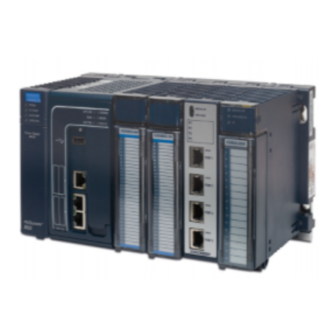
- Page 1 Automation & Controls Programmable Control Products RX3i & RSTi-EP PROFINET IO-Controller User PACSystems* Manual GFK-2571N RX3i & RSTi-EP PROFINET IO-Controller User Manual GFK-2571N May 2018 For Public Disclosure...
- Page 2 These instructions do not purport to cover all details or variations in equipment, nor to provide for every possible contingency to be met during installation, operation, and maintenance. The information is supplied for informational purposes only, and GE makes no warranty as to the accuracy of the information included herein. Changes, modifications, and/or improvements to equipment and specifications are made periodically and these changes may or may not be reflected herein.
- Page 3 Online technical support and GlobalCare www.geautomation.com/support Additional information www.geautomation.com Solution Provider solutionprovider.ip@ge.com Technical Support If you have technical problems that cannot be resolved with the information in this manual, please contact us by telephone or email, or on the web at www.geautomation.com/support...
-
Page 4: Table Of Contents
Table of Contents RX3i & RSTi-EP PROFINET IO-Controller User Manual GFK-2571N Table of Contents ............................i Table of Figures .............................. vi Chapter 1 Introduction ......................... 1 Revisions in this Manual ......................2 PROFINET Controller Description ..................4 1.2.1 PNC001 Description ..............................4 1.2.2 Embedded PROFINET Controller ........................... - Page 5 Contents Glossary ............................. 28 Documentation ........................30 Chapter 2 Installation ......................... 31 Pre-Installation Check ......................32 Installation in Hazardous Areas ..................33 2.2.1 ATEX Marking ................................33 Removing the Backplane Knockout ..................34 Module Installation ......................... 35 Module Removal ........................35 Hot Insertion and Removal ....................
- Page 6 Contents Configuring PROFINET System Redundancy..............55 Exploring PROFINET Networks .................... 56 3.5.1 Configuring a PROFINET Controller on a LAN....................57 3.5.2 Configuring PROFINET Controller Parameters ..................... 58 Configuring PROFINET LANs ....................62 3.6.1 Configuring the LAN Properties .......................... 63 Adding a VersaMax PROFINET Scanner to a LAN............. 65 3.7.1 Configuring VersaMax PROFINET Scanner Parameters ................
- Page 7 Contents 4.7.7 PACSystems CPU Defaults - Outputs ....................... 99 Chapter 5 Diagnostics ........................101 Power-up and Reset (PNC001 Module) ................102 5.1.1 Module Restart ............................... 102 5.1.2 Problems During Power-up and Reset ......................103 5.1.3 Transitioning to Firmware Update Mode ..................... 103 Special LED Blink Patterns ....................
- Page 8 Contents Ring Topology with One Controller .................. 135 Ring Topology with Multiple Controllers ................ 136 Setting Up Media Redundancy Protocol ................. 137 6.4.1 Media Redundancy Setup for a PROFINET Controller ................137 Sequence for Enabling Media Redundancy ..............138 Sequence for Replacing a Media Redundancy Manager ..........139 Procedure for Disabling Media Redundancy ..............
-
Page 9: Table Of Figures
Contents Table of Figures Figure 1: IC695PNC001-Bxxx Front View ___________________________________________________________ 4 Figure 2: IC695PNC001-Ax Controls & Indicators ____________________________________________________ 10 Figure 3: IC695PNC001-Bxxx Controls & Indicators __________________________________________________ 10 Figure 4: PNC001 Ethernet Ports Location and Type _________________________________________________ 12 Figure 5: CPE100/CPE115 Ethernet Ports Location and Type __________________________________________ 12 Figure 6: RX3i System with one PROFINET Controller and one PROFINET LAN _____________________________ 16 Figure 7: RX3i System with one PROFINET Controller and multiple PROFINET LANs ________________________ 17 Figure 8: RX3i System interfacing with Third-Party Devices and with PME Programmer ____________________ 18... - Page 10 Contents Figure 50: Setting the Communication Properties of a LAN ____________________________________________ 63 Figure 51: Select PNS from Catalog ______________________________________________________________ 65 Figure 52: Select PNS Type _____________________________________________________________________ 65 Figure 53: PNS Attached to PNC001 in PME Navigator _______________________________________________ 65 Figure 54: Select PNS for Parameter Configuration __________________________________________________ 66 Figure 55: PNS Parameters Settings Tab __________________________________________________________ 66 Figure 56: PNS Parameters Redundancy Tab _______________________________________________________ 67 Figure 57: PNS Parameters Media Redundancy Tab _________________________________________________ 67...
-
Page 12: Chapter 1 Introduction
Chapter 1 Introduction This chapter introduces the PACSystems RX3i & RSTi-EP PROFINET system and describes the various forms of RX3i & RSTi-EP PROFINET Controllers: The IC695PNC001 module (abbreviated PNC001), which is a rack-mounted module residing in the CPU Rack; there are two hardware versions of this module: IC695PNC001-Ax and IC695PNC001-Bxxx. -
Page 13: Revisions In This Manual
Chapter 1. Introduction Revisions in this Manual Date Description ▪ Corrected the units associated with Network Transit Time, which is a millisecond. 2018 ▪ Clarification added for footnote 3. ▪ Added introductory section on PROFINET System Redundancy (Section 1.6.8). ▪ Added a note on Compression at Section 1.6.1. - Page 14 Chapter 1. Introduction Date Description Mar- ▪ Chapter 1, Introduction: made edits to clarify that products other than VersaMax 2014 support redundancy. ▪ Chapter 4, PROFINET System Operation: made edits to support redundancy. ▪ Chapter 6, Redundant Media: added table to show which PROFINET Scanner/Device supports PROFINET Media Redundancy Protocol (MRP), and made other edits to clarify that products other than VersaMax support redundancy.
-
Page 15: Profinet Controller Description
PNC001 Description The PACSystems RX3i PROFINET Controller module, IC695PNC001, connects a PACSystems RX3i controller to a PROFINET network. It enables the RX3i controller to communicate with IO-Devices on the network. The PNC001 provides all the functions, services, and protocols required for certification as a PROFINET IO Version 2.2 IO Controller, running at both... -
Page 16: Embedded Profinet Controller
Chapter 1. Introduction 1.2.2 Embedded PROFINET Controller CPE400, CPE330 and CPE100/CPE115 feature an Embedded PROFINET IO-Controller function. This feature permits LAN2 to be configured as a PROFINET Controller similar to PNC001 in functionality, but without requiring the presence of a PNC001 rack-mounted module. In the following Specifications section, the physical specifications related to rack mounting do not apply to the embedded PROFINET Controllers. -
Page 17: Pnc001 Module Specifications
Chapter 1. Introduction PNC001 Module Specifications PROFINET Version 2.2 General Class A IO-Controller PROFINET Support Redundantly controlled operation conforms to PROFINET V2.3 Type S-2 System Redundancy. Note that the CPE100/CPE115 is a simplex PROFINET IO-Controller. Requires CPU315, CPU320, CPE305, CPE310 or CPE330 with firmware CPU Compatibility version 7.0 or higher. - Page 18 2176 (does not include backplanes, power supplies, or I/O modules) For product standards, general operating specifications, and installation requirements, refer to the PACSystems RX3i System Manual, GFK-2314. Effective with firmware v9.30, CPE100/CPE115 supports MRP. In the case of CPE330, with embedded PROFINET activated, it is possible to have five PROFINET Controllers. However, in the rare case of having all 5 PNCs configured on the same LAN, and then invoking redundancy, each CPU is again restricted to a limit of 4 PNCs (in order to satisfy the overall limit of 8 PNCs per LAN).
- Page 19 Chapter 1. Introduction Maximum Number of Nodes per Network based on Topology • For a network using MRP ring topology, the maximum number of nodes is 64 (consisting of the PNC001 PROFINET Controller(s) plus up to 62 or 63 IO-Devices). If the ring uses Media Redundancy Protocol, this means one Media Redundancy Manager and up to 63 clients.
-
Page 20: Operating Range For Surrounding Air Temperature
Chapter 1. Introduction Operating Range for Surrounding Air Temperature 0 to 60°C surrounding air temperature PNC001-AX -25 to 60°C surrounding air temperature PNC001-BXXX 1.4.1 Operating Temperature De-Rating: The operating temperature range is specified for the module and not the system as a whole. As a guideline, if the module is next to hot neighbor modules on each side the maximum operating ambient temperature should be de-rated as described below: •... -
Page 21: Pnc001 Module Controls And Indicators
Chapter 1. Introduction PNC001 Module Controls and Indicators Figure 3: IC695PNC001-Bxxx Controls & Figure 2: IC695PNC001-Ax Controls & Indicators Indicators PACSystems* RX3i & RSTi-EP PROFINET IO-Controller User Manual GFK-2571N... -
Page 22: Pnc001 Hardware Implementions (-Ax & -Bxxx)
Chapter 1. Introduction 1.5.1 PNC001 Hardware Implementions (-Ax & -Bxxx) In January 2018, an updated hardware implementation(-Bxxx) replaced the earlier version (-Ax) of the rack- mounted PNC001. The following are the differences between these two hardware implementations. Topic -Bxxx Appearance Figure 2 Figure 3 Case... -
Page 23: Ethernet Network Ports
Chapter 6 provides additional information about Redundant Media. The PROFINET protocol supported by the PACSystems RX3i PROFINET modules can be sent and received over any of the four external ports on PNC001. -
Page 24: Usb Port(S)
Chapter 1. Introduction Ethernet Port Status Indicators Each external switched port has an associated link-up/link-down status bit that can be monitored by the RX3i CPU to check the operating status of the port (see Status Reporting in Chapter 5, Diagnostics, for information about the PROFINET Controller status bits). -
Page 25: Profinet Networks For Pacsystems
IO Devices on the network can consist of the I/O modules installed in a rack, each containing a PROFINET Scanner (PNS) as its head-end, such as the GE products listed above. The network may also include a wide range of third-party IO Devices, such as pressure gauges and motor actuators, that are connected directly to the PROFINET network. -
Page 26: Compression
Chapter 1. Introduction 1.6.1 Compression Due to the smaller memory capacities of CPE302, CPE305 and CPE310, these CPUs require "Compression" when attaching RX3i PNS or CEP to their PROFINET configuration. • CPE302: User MUST use Target PLC parameter with "Compression" set to HIGH. •... -
Page 27: Basic System: One Rx3I Cpu And One Profinet Controller Using A Single Port
Basic System: One RX3i CPU and One PROFINET Controller using a single port Figure 6 shows a basic system with one PACSystems RX3i CPU node having one PROFINET Controller, and one PROFINET network with three VersaMax Scanners and one third-party IO-Device. Up to 128 IO-Devices can be installed on an RX3i PROFINET network. -
Page 28: Basic System: One Rx3I Cpu And One Profinet Controller Using Multiple Ports
Basic System: One RX3i CPU and One PROFINET Controller using multiple ports The illustration below shows a basic system with one PACSystems RX3i CPU node that has one RX3i PROFINET Controller module controlling one PROFINET network. The network can connect up to 128 compatible IO- Devices, including any combination of GE PROFINET Scanners and third-party IO-Devices. -
Page 29: Basic System: Third-Party Devices And Pme Programmer
Chapter 1. Introduction 1.6.4 Basic System: Third-Party Devices and PME Programmer Third-party IO Devices can be used with the RX3i PROFINET Controller if their manufacturer provides a GSDML file that can be imported into Proficy Machine Edition (PME). The GSDML file defines the characteristics of the IO-Device and its I/O modules. -
Page 30: Systems With One Rx3I Cpu And Two Profinet Controllers
Chapter 1. Introduction 1.6.5 Systems with One RX3i CPU and Two PROFINET Controllers Both examples in this section show systems with one RX3i CPU that has two PROFINET Controller modules. The PROFINET network can serve up to 63 IO-Devices (ring topology) or 128 IO-Devices (in star topology). Note that multiple PNC001 modules in the same rack are not synchronized;... -
Page 31: Figure 10: Rx3I System With Two Pnc001 Modules And Two Daisy-Chain Profinet Lans
Chapter 1. Introduction In Figure 10, the two PROFINET Controllers are connected to separate networks. The maximum number of IO- Devices with multiple PROFINET Controllers in the same RX3i controller is 255. NOTE: Daisy-chain shown for clarity. A star or ring topology is preferred. -
Page 32: One Rx3I Cpu With Four Controllers On Separate Networks
A star or ring topology is preferred. IO-Device IO-Device Figure 11: RX3i System with four PNC001 modules and four Daisy-Chain PROFINET LANs As in the other examples, other GE IO-Devices can be substituted for the VersaMax PROFINET Scanners. GFK-2571N May 2018... -
Page 33: Two Rx3I Cpus With Two Profinet Networks And One Ethernet Network
Chapter 1. Introduction 1.6.7 Two RX3i CPUs with Two PROFINET Networks and One Ethernet Network Figure 12 shows two RX3i CPU nodes, each with one RX3i PROFINET Controller module and one RX3i Ethernet Transmitter Module (ETM). The PROFINET Controller modules are connected to separate networks (IO LAN1 and IO LAN2 in the illustration). -
Page 34: Systems That Use Profinet System Redundancy (Pnsr)
Chapter 1. Introduction 1.6.8 Systems that use PROFINET System Redundancy (PNSR) PACSystems support S2 type PNSR, as diagrammed in Figure 13. The ‘S’ denotes that the IO Device has single network support. PROFINET defines an ‘R’ option in which the IO Device may have redundant network interfaces which could be on different networks. -
Page 35: Systems That Use Hot Standby Cpu Redundancy
Chapter 1. Introduction 1.6.9 Systems that use Hot Standby CPU Redundancy Figure 14 shows a Hot Standby CPU Redundancy system that uses a PROFINET I/O network with MRP ring topology. Use of MRP ring topology is recommended because it eliminates the I/O network as a single point of failure. -
Page 36: Rsti-Ep Standalone Cpu With Embedded Profinet Controller Using A Single Port
Chapter 1. Introduction 1.6.10 RSTi-EP Standalone CPU with embedded PROFINET Controller using a single port Figure 15 shows a basic system with one PACSystems RSTi-EP CPU node with embedded PROFINET Controller, and one PROFINET network with two VersaMax, one RSTi-EP Scanners and one third-party IO-Device. Up to 8 IO-Devices can be installed on an RSTi-EP PROFINET network. -
Page 37: Rsti-Ep Standalone Cpu With Embedded Profinet Controller Using Multiple Ports
PROFINET Controller controlling one PROFINET network. The network can connect up to 8 compatible IO- Devices, including any combination of GE PROFINET Scanners and third-party IO-Devices. Figure 16 shows one RSTi-EP CPE100/CPE115 embedded PROFINET Controller that is directly connected to three separate IO-Devices in a Star topology. -
Page 38: Rsti-Ep Standalone Cpu With Embedded Profinet Controller Using Mrp
Chapter 1. Introduction 1.6.12 RSTi-EP Standalone CPU with embedded PROFINET Controller using MRP Figure 17 shows one RSTi-EP CPE100/CPE115 embedded PROFINET Controller that uses a PROFINET I/O network with MRP ring topology. CPE100/CPE115 LAN2 Port 2 & Port 3 support Media Redundancy and on configuring MRP as Manager / Client LAN2 Port 4 can be used for connecting Simplex PROFINET devices or any other Ethernet Protocols such as Modbus, SRTP, and EGD. -
Page 39: Glossary
Command Line Interface CPU Node In a PACSystems RX3i PROFINET network, a CPU Node is a node in which a PACSystems RX3i CPU is connected to the PROFINET network. Communication Relationship. PROFINET term for a channel that is established within an Application Relationship (AR) to transfer specific data between an IO-Controller/Supervisor and a given IO-Device. - Page 40 Chapter 1. Introduction Glossary, continued PROFINET Controller: Typically, the generic PROFINET Controller function. PNC001 represents a slot-mounted product (IC695PNC001). Embedded PROFINET Controllers may be configured on LAN2 for CPE400, CPE330 and CPE100/CPE115. Both embedded and slot-mounted perform the same functions on the PROFINET network, but there are differences to be noted in installation, configuration, operation and performance.
-
Page 41: Documentation
PACSystems RXi, RX3i, RX7i and RSTi-EP Controller Secure Deployment Guide GFK-2830 RX3i Manuals PACSystems RX3i System Manual GFK-2314 PACSystems RX3i PROFINET Controller Command Line Interface Manual GFK-2572 PACSystems RX3i Max-On Hot Standby Redundancy User’s Manual GFK-2409 PACSystems RX3i PROFINET Scanner Manual... -
Page 42: Chapter 2 Installation
Installing SFP devices • LED indications • Installing the USB Port Driver • Firmware updates • Time synchronization with RX3i CPU For additional information about system installation, also refer to the PACSystems RX3i Systems Manual, GFK- 2314. GFK-2571N May 2018... -
Page 43: Pre-Installation Check
As the consignee, it is your responsibility to register a claim with the carrier for damage incurred during shipment. However, Automation & Controls at GE Energy Connections will fully cooperate with you, should such action be necessary. -
Page 44: Installation In Hazardous Areas
Chapter 2. Installation Installation in Hazardous Areas EQUIPMENT LABELED WITH REFERENCE TO CLASS I, GROUPS A, B, C & D, DIV. 2 HAZARDOUS LOCATIONS IS SUITABLE FOR USE IN CLASS I, DIVISION 2, GROUPS A, B, C, D OR NON-HAZARDOUS LOCATIONS ONLY EXPLOSION HAZARD - SUBSTITUTION OF COMPONENTS MAY IMPAIR SUITABILITY FOR CLASS I, DIVISION 2. -
Page 45: Removing The Backplane Knockout
Removing the Backplane Knockout The IC695PNC001 must be installed in the main (CPU) rack of the RX3i system, using a Universal Backplane such as IC695CHS007, CHS012 or CHS016. For details, refer to the PACSystems RX3i System Manual, GFK-2314. The rear of the PNC001-Ax module has an exposed heat sink and backplane connector. Before inserting the module into the backplane, remove the plastic knockout in the slot into which the module will be placed. -
Page 46: Module Installation
Chapter 2. Installation Module Installation • RX3i rack power may be off or on (see Hot Insertion and Removal for details). • Holding the module firmly, align the module with the correct slot and connector. • Engage the module’s rear pivot hook in the notch on the top of the backplane (1). -
Page 47: Hot Insertion And Removal
For a full discussion of this topic, refer to the Hot Insertion and Removal section in the PACSystems RX3i System Manual, GFK-2314. The PNC001 module must be properly seated with the latch engaged (PNC001-Ax only) and all pins connected within 2 seconds. -
Page 48: Ethernet Port Connections
Chapter 2. Installation Ethernet Port Connections Each port on an RX3i PROFINET Controller operates independently. This is true for all ports on the PNC001 module and for ports assigned to embedded PROFINET Controllers. In this way, devices that operate at different speeds and/or duplex modes may be attached to a compatible port. -
Page 49: Figure 22: Interconnect Using Copper Cables / Rj45 Connectors
Network Cabling and Connector Types Copper: up to 100 Meters between Devices All Automation & Controls products from GE Energy Connections use RJ45 connectors for copper connections. Copper cabling and connections are easily available in the general market and support distances of up to 100m. -
Page 50: Figure 25: Cat5E/Cat6 (Shielded Or Unshielded) With Rj 45 Connector
Chapter 2. Installation 2.7.2.2 Network Cabling and Connector Examples Figure 25: CAT5e/CAT6 (shielded or unshielded) with RJ 45 Connector Figure 26: Multi-Mode Fiber with LC connector Figure 27: Single-Mode Fiber with LC connector GFK-2571N May 2018... -
Page 51: Installing Sfp Devices
Chapter 2. Installation 2.7.3 Installing SFP Devices SFP (Small Form-Factor Pluggable) devices can be installed in Port 3 and Port 4 of the PROFINET Controller. See section 2.7.3.1, SFP Modules for Ethernet Ports, for a list of supported SFP devices, media types and distances. - Page 52 Chapter 2. Installation 2.7.3.1 SFP Modules for Ethernet Ports Each Small Form-Factor Pluggable (SFP) cage on the bottom of a PROFINET Controller module can accept a: • 10/100/1000 Mbps copper SFP, • 100Mbps Single-Mode Fiber SFP, • 100Mbps Multi-Mode Fiber SFP, •...
-
Page 53: Removing Sfp Devices
Chapter 2. Installation 2.7.3.2 Typical SFP Modules Below are images of the two types of Ethernet SFPs. The Single- and Multi-Mode Fiber SFPs accept an LC Connector. The Copper SFPs accept an RJ45 connector. Figure 29: Fiber SFP showing LC Connector Figure 30: Copper SFP showing RJ45 Connector 2.7.4 Removing SFP Devices... -
Page 54: Pnc001 Led Behavior
Chapter 2. Installation PNC001 LED Behavior 2.8.1 Power-up LED Patterns At power-up, the LEDs show the blink patterns described below. The LEDs also blink diagnostic patterns for certain operating errors and for module identification. See Chapter 5, Diagnostics for a description of those special blink patterns. -
Page 55: Detailed Led Descriptions
Chapter 2. Installation 2.8.2 Detailed LED Descriptions 2.8.2.1 OK LED The OK LED indicates whether the module is able to perform normal operation. Green, ON Green, blink pattern Fatal error. Flashes once between error codes blinked on the OK LED Amber, blink pattern Fatal error Not OK... - Page 56 Chapter 2. Installation 2.8.2.6 ACTIVE LED The ACTIVE LED indicates the overall status of PROFINET connections. Green, ON All configured PROFINET devices have established PROFINET connections Green, blink pattern Fatal error. Flashes once between error codes blinked on the OK LED Amber, ON At least one configured PROFINET device has established a PROFINET connection, but other configured PROFINET devices are not connected...
-
Page 57: Installing The Usb Port Driver
Chapter 2. Installation Installing the USB Port Driver The USB Ports on CPUs which support the embedded PROFINET function operate independently of the PROFINET Controller function itself. Refer to the documentation for the related CPU. For the slot-mounted PNC001 (-Ax module only), set up use of the module’s USB port in either of these ways: Run the provided driver-install application before connecting the computer’s USB port to the USB port on the PNC001 module for the first time. -
Page 58: Firmware Updates
Chapter 2. Installation 2.10 Firmware Updates 2.10.1 PNC001 Firmware Updates Firmware for PNC001-Ax is only compatible with PNC001-Ax hardware. Firmware for PNC001-Bxxx is only compatible with PNC001-Bxxx hardware. They are not interchangeable. The RX3i PROFINET Controller firmware is updated via the CPU in the rack in which the PNC001 module is located. -
Page 59: Pnc001 Time Synchronization With The Host Rx3I Cpu
Chapter 2. Installation 2.11 PNC001 Time Synchronization with the Host RX3i CPU The internal clock value of a PNC001 module may be displayed in Command Line Interface (CLI) commands, and it is used to timestamp entries in the PROFINET Controller Local Fault Log as they occur. The internal clock of the PNC001 module is synchronized with the RX3i CPU clock whenever the PNC001 module is: •... -
Page 60: Chapter 3 Configuration
Chapter 3 Configuration This chapter explains how to configure an RX3i PROFINET Controller and its IO devices in a PACSystems RX3i controller system. Additional information about RX3i configuration is available in other PACSystems documentation and in the Logic Developer online help. -
Page 61: Configuration Overview
Chapter 3. Configuration Configuration Overview The Proficy Machine Edition PLC Logic Developer programmer is used to create and download the configuration for an RX3i PROFINET network and its devices. 3.1.1 System Planning 3.1.1.1 Device Ownership Note that all modules in an IO-Device must belong to the same PROFINET network, that is, they are all owned by the same PROFINET Controller. -
Page 62: Basic Configuration Steps
Chapter 3. Configuration 3.1.2 Basic Configuration Steps The basic configuration steps, described in this chapter, are: • In the hardware configuration, configure LAN2 as an embedded PROFINET LAN, or, for slot-mounted hardware, add a PNC001 module to the RX3i main rack. This automatically associates a LAN with the PROFINET Controller. -
Page 63: Configuration Tools
Chapter 3. Configuration Configuration Tools Proficy Machine Edition (PME) is the primary tool used to configure an RX3i PROFINET network. In addition, for the PNC001 module only, certain parameters can be set from a computer through the Command Line Interface (CLI). -
Page 64: Configuring An Rx3I Profinet Controller
Chapter 3. Configuration Configuring an RX3i PROFINET Controller 3.3.1 Configuring a Rack-Mounted RX3i PROFINET Controller (PNC001) This section describes one technique to configure the parameters of an RX3i IC695PNC001. The PROFICY Machine Edition InfoViewer describes alternative menus and keyboard operations that can be used to perform the same functions. -
Page 65: Configuring An Embedded Rsti-Ep Profinet Controller
Chapter 3. Configuration 3.3.3 Configuring an Embedded RSTi-EP PROFINET Controller CP100 support configuring LAN2 as an embedded PROFINET Controller. Instead of Configuring a PNC001 into a rack/slot location (Figure 32), LAN2 in the target is configured as a PROFINET Controller (Figure 34). Figure 34: CPE100/CPE115 Embedded PROFINET Controller Configured on LAN2 PACSystems* RX3i &... -
Page 66: Configuring Profinet System Redundancy
Chapter 3. Configuration Configuring PROFINET System Redundancy To enable PROFINET System Redundancy in a CPE400 project, select the CPE400 target in the PME Navigator and use the Property Inspector to change the Enable Redundancy target property to True. To enable PROFINET System Redundancy in a CPE330 project, select the CPE330 target in the PME Navigator and use the Property Inspector to change the Enable Redundancy target property to True. -
Page 67: Exploring Profinet Networks
Chapter 3. Configuration Exploring PROFINET Networks To explore the PROFINET networks in the system while PROFICY Machine Edition is online with the RX3i system, and while the PROFINET Controller is connected to its network, right-click on the Target icon (not the PNC) and select Explore PROFINET Networks under the Online Commands menu item. -
Page 68: Configuring A Profinet Controller On A Lan
Chapter 3. Configuration 3.5.1 Configuring a PROFINET Controller on a LAN Adding the first PROFINET Controller to a project automatically creates a LAN associated with it. For each subsequent PROFINET Controller that is added to a project, an existing LAN can be selected or a new LAN can be created. -
Page 69: Configuring Profinet Controller Parameters
Chapter 3. Configuration 3.5.2 Configuring PROFINET Controller Parameters Configure the PROFINET Controller parameters by editing the tabs as appropriate. The parameters are divided among the tabs, and the options are available in the Inspector view. 3.5.2.1 PROFINET Controller Parameters (Settings Tab) Figure 40: PROFINET Controller Settings Tab (PNC001) Figure 41: PROFINET Controller Settings Tab (Embedded PNC) Note that the embedded PROFINET Controller does not have any SFP cages, and therefore has... -
Page 70: Figure 42: Setting The Status Reference Address
Chapter 3. Configuration Status Address, Length: The Status Address is the reference memory location for the 32 bits of status data associated with the PROFINET Controller itself. The Status address can be assigned to valid %I, %Q, %R, %AI, %AQ, %W, %G, %T or %M memory by right-clicking on the Status Address field and selecting the Data Entry tool. - Page 71 Chapter 3. Configuration I/O Scan Set: The scan set for the PROFINET Controller defaults to scan set 1. Scan sets are defined in the CPU’s Scan Sets tab. The valid range is 1 through 32; the default value is 1. Refer to the PACSystems RX7i and RX3i CPU Reference Manual, GFK-2222, for a discussion of CPU scan sets.
-
Page 72: Figure 44: Setting Media Redundancy Parameters
Chapter 3. Configuration 3.5.2.2 PROFINET Controller Parameters (Media Redundancy Tab) By default, a PROFINET Controller is not set up for Media Redundancy. If the system will use Media Redundancy (see Chapter 6 for more information), open the Media Redundancy tab and select either Client or Manager: Figure 44: Setting Media Redundancy Parameters If the PROFINET Controller will be a Media Redundancy Client, click on Ring Port 1 and Ring Port 2 to choose the module ports and Domain Name that will be used. -
Page 73: Configuring Profinet Lans
Chapter 3. Configuration Configuring PROFINET LANs To view the LANs in the project, click on Tools in the Machine Edition toolbar, and select LAN View from the menu. If no LANs and no PROFINET Controllers have been added to the project, the LAN View is empty: Figure 47: Configuring the PROFINET LAN Adding a PROFINET Controller to the project automatically creates a new LAN. -
Page 74: Configuring The Lan Properties
Chapter 3. Configuration 3.6.1 Configuring the LAN Properties Machine Edition automatically assigns a set of default properties to the LAN. Select the LAN icon in the LAN viewer to display or edit its communications properties in the Inspector pane: Figure 50: Setting the Communication Properties of a LAN LAN Name: this can be edited or the default name can be used. - Page 75 Chapter 3. Configuration If the subnet mask is improperly set, devices may be unable to communicate on the network and might disrupt network communications. Contact your network administrator to assign values that work with an existing network. Caution Subnet Mask: Mechanism that filters network communications so that they are routed only to subnets to which they are addressed.
-
Page 76: Adding A Versamax Profinet Scanner To A Lan
Chapter 3. Configuration Adding a VersaMax PROFINET Scanner to a LAN To add a VersaMax PNS to a LAN, in the Navigator right-click on the IC695PNC001 module and select Add IO-Device. The PROFINET Device Catalog appears. Figure 51: Select PNS from Catalog In the PROFINET Device Catalog, expand the VersaMax PNS line and choose the module type: Figure 52: Select PNS Type Select the PNS type and click OK. -
Page 77: Configuring Versamax Profinet Scanner Parameters
Chapter 3. Configuration 3.7.1 Configuring VersaMax PROFINET Scanner Parameters After adding a VersaMax PNS to the LAN, its parameters can be configured by either double-clicking on the Scanner in the Navigator, or right-clicking and selecting Configure from the menu. Figure 54: Select PNS for Parameter Configuration 3.7.1.1 PROFINET Scanner Parameters (Settings Tab) Figure 55: PNS Parameters Settings Tab... -
Page 78: Figure 56: Pns Parameters Redundancy Tab
Chapter 3. Configuration 3.7.1.2 PROFINET Scanner Parameters (Redundancy Tab) On the Redundancy tab, select whether or not the PNS is redundantly controlled. Figure 56: PNS Parameters Redundancy Tab When the PNS supports PROFINET System Redundancy and is configured in an HSB CPU Redundancy system, the Programmer automatically selects redundant control by setting the Redundancy Mode parameter to HSB CPU Redundancy. -
Page 79: Figure 59: Pns Parameters Module Parameters Tab
Chapter 3. Configuration 3.7.1.4 PROFINET Scanner Parameters (Module Parameters Tab) The PNS has one module parameter: Figure 59: PNS Parameters Module Parameters Tab By default, the PNS module LEDs will blink a fault code if a fatal error occurs. This can be changed to cause the PNS to restart instead. -
Page 80: Figure 61: Pns Interface Parameter Details
Chapter 3. Configuration Double-clicking on the PNS module’s Interface 1 icon in the Navigator displays additional GSDML parameters: Figure 61: PNS Interface Parameter Details Double-clicking on the PNS module’s Port 1 and Port 2 icons in the Navigator also displays additional GSDML parameters for the scanner: Figure 62: PNS Port Parameter Details GFK-2571N... -
Page 81: Adding Versamax Profinet Scanner Power Supplies
Chapter 3. Configuration 3.7.2 Adding VersaMax PROFINET Scanner Power Supplies The VersaMax PNS has connectors for either one or two power supplies. If necessary, additional power supplies can also be located between modules in the remote node. To configure the one or two power supplies that will be installed directly on the PNS module, right-click on the Slot 0 icon in the Navigator, then select Change Submodule List. -
Page 82: Adding Versamax Modules To A Remote Node
Chapter 3. Configuration 3.7.3 Adding VersaMax Modules to a Remote Node The PNS remote node can contain the module types listed in the VersaMax PROFINET Scanner Manual, GFK-2721. However, it cannot contain the following expansion modules or communications modules: Unsupported VersaMax Modules Asi Network Master Module IC200BEM104 DeviceNet Network Control Module... -
Page 83: Installing Power Supplies Between Modules
Chapter 3. Configuration 3.7.4 Installing Power Supplies Between Modules Additional power supplies may be installed between modules, if necessary. Power Supply modules added in this fashion will service the power requirements of modules located further right in the same rack. To add a power supply between modules, expand the Power Supply Module node in the Change Module List. -
Page 84: Configuring Versamax Module Parameters
Chapter 3. Configuration 3.7.5 Configuring VersaMax Module Parameters After adding VersaMax modules to the remote node, the parameters for each must be configured. For all VersaMax modules, this includes configuring a set of basic parameters (such as: Reference Address, Length, Scan Set, Carrier, Report Faults). -
Page 85: Figure 70: Selecting The Sub-Module Configuration With Jumper Settings Declared
Chapter 3. Configuration 3.7.5.2 The Change Submodule List On the Change Submodule List, select the type of inputs or outputs that will be wired to the module, and drag the selection to the Content field in the left pane. For example: Figure 70: Selecting the Sub-Module Configuration with Jumper Settings Declared Once the Content field has been populated, the Description field indicates how the physical jumpers in the module should be configured. -
Page 86: Adding A Third-Party Io-Device To A Lan
Chapter 3. Configuration Adding a Third-Party IO-Device to a LAN To add a third-party IO-Device to a LAN, in the Navigator right-click on the connected IC695PNC001 module and select Add IO-Device. Select the module in the PROFINET Device Catalog and click Have GSDML: Figure 72: Selecting Third-Party Modules for Addition to LAN To be included in the system configuration, any third-party IO-Device requires a GSDML file. -
Page 87: Editing Third-Party Io-Device Parameters
Chapter 3. Configuration 3.8.1 Editing Third-Party IO-Device Parameters To configure the parameters of a third-party IO-Device, either double-click on the module in the Navigator, or right-click on the module and select Configure from the menu. Upon opening the IO-Devices configuration, you will see an IO-Device Access Point tab, a GSDML Details tab, and, possibly, additional parameter tabs (if defined by the device manufacturer in the associated GSDML file). -
Page 88: Figure 77: Third-Party I/O: Configure Ring Ports For Media Redundancy Manager
Chapter 3. Configuration If the IO-Device will be a Media Redundancy Manager, edit the Ring Port settings as above. You can also change the Default Test Interval in the range of 1 to 1000ms and the Test Monitoring Count (2 to 10). For the Media Redundancy Manager, the Domain Name can be edited by typing over the default name. -
Page 89: Configuring Sub-Modules Of A Third-Party Io-Device
Chapter 3. Configuration 3.8.2 Configuring Sub-Modules of a Third-Party IO-Device To configure the sub-modules of a third-party IO-Device, expand it in the Navigator. For example: Figure 79: Expand Third-Party I/O Device The device in Figure 79 is a switch. The parameters of its ports can be viewed and edited by either double- clicking on a port, or selecting a port then right-clicking and selecting Configure from the menu. -
Page 90: Viewing / Editing Io-Device Properties
Chapter 3. Configuration Viewing / Editing IO-Device Properties In addition to the parameter configuration described on the previous pages, all IO-Devices (PNS modules and third-party devices) have other configurable properties. These properties are displayed in the Machine Edition Inspector pane when the device is selected in the Navigator. In the Inspector, properties that are not grayed-out can be used as is or edited as appropriate. -
Page 91: Figure 84: Assigning Reference Variable To Io-Device
Chapter 3. Configuration Reference Variable: to be used by the PNIO_DEV_COMM logic blocks. The choice defaults to none. To create a reference variable for the device, use the drop-down list to select Create. The variable name appears in the Inspector field: Figure 84: Assigning Reference Variable to IO-Device IO LAN: (read-only) identifies the LAN of which the IO-Device is a part. -
Page 92: Assigning Io-Device Names
Chapter 3. Configuration 3.10 Assigning IO-Device Names After the PNS and third-party IO-Devices on the LAN have been entered into the configuration, the Discovery and Configuration Protocol (DCP) tool in Machine Edition must be used to assign a name to each IO-Device. This step is required before downloading the configuration from the PROFINET Controller. -
Page 93: Figure 88: List Of Device Names On Lan With Status Indications
Chapter 3. Configuration Once a LAN is selected, click on Refresh Device List to display a list of actual devices on the LAN. Each device can be in one of three conditions as indicated by the symbol in the Status column: indicates that the Device Name, IP Address, Subnet and Gateway of the actual device matches the configured device of the same Device Name residing on the selected LAN. -
Page 94: After The Configuration Is Stored To The Rx3I Cpu
Chapter 3. Configuration 3.11 After the Configuration is Stored to the RX3i CPU The configuration is stored to the RX3i CPU using Machine Edition. For complete instructions, refer to the PACSystems system documentation. If the configuration is stored to non-volatile memory or is battery-backed, the CPU maintains configuration data over power cycles. -
Page 96: Chapter 4 Profinet System Operation
Chapter 4 PROFINET System Operation This chapter describes: • PROFINET Operation Overview PROFINET Communications Application Relationships Types of PROFINET Communications External Switch VLAN Priority Settings • Operations of the PROFINET Controller in the RX3i and RSTi-EP Duplicate Device IP Address Detection Duplicate Controller IP Address Detection Resolving Duplicate IP Addresses •... -
Page 97: Profinet Operation Overview
Chapter 4. PROFINET System Operation PROFINET Operation Overview An RX3i or RSTi-EP CPU uses PROFINET communications for data exchange between it (as the PROFINET Controller) and IO-Devices connected on the same PROFINET network and configured to be under its control. The PROFINET Controller function may be realized by utilizing the embedded PROFINET Controller option in RX3i CPE400 LAN2 or CPE330 LAN2 or RSTi-EP CPE100/CPE115 LAN2. -
Page 98: Profinet Communications
Chapter 4. PROFINET System Operation 4.1.1 PROFINET Communications Communications on a PACSystems PROFINET network use the standard PROFINET communications described in this section. 4.1.1.1 Application Relationships Before an PACSystems PROFINET IO-Controller can exchange data with a PROFINET IO-Device, an Application Relationship (connection) must be established between the devices. -
Page 99: Figure 90: Real-Time And Non-Real-Time Data Communications
Chapter 4. PROFINET System Operation 4.1.1.2 Types of PROFINET Communications PACSystems PROFINET Controllers use two types of PROFINET communication transfers: real-time and non- real-time. The illustration below shows real-time communications as solid lines and non-real-time communications as dashed lines. Figure 90: Real-Time and Non-Real-Time Data Communications •... - Page 100 Chapter 4. PROFINET System Operation 4.1.1.3 External Switch VLAN Priority Settings The PROFINET-IO specification indicates the VLAN priorities for each type of Ethernet traffic that originates from a PROFINET node. VLAN priorities range from 0 to 7, with 7 being the highest. The PACSystems PROFINET Controller supports just four traffic classes, giving four levels of preference.
-
Page 101: Operations Of The Profinet Controller In The Pacsystems System
Chapter 4. PROFINET System Operation Operations of the PROFINET Controller in the PACSystems System The PROFINET IO-Controller in the PACSystems controller system performs the following operations: • Consumes PROFINET IO-Device configuration from the CPU and transfers it to the IO-Devices over the PROFINET network. -
Page 102: Duplicate Profinet Io-Controller Ip Address
Chapter 4. PROFINET System Operation 4.2.2 Duplicate PROFINET IO-Controller IP Address The PROFINET IO-Controller detects that a network device has the same IP Address as its own ➢ during power-up, ➢ whenever a new hardware configuration is downloaded from the programmer, and ➢... -
Page 103: I/O Scanning
Chapter 4. PROFINET System Operation I/O Scanning In the PACSystems PROFINET network, multiple I/O cycles run asynchronously and independently. Figure 91 illustrates typical cycles in a system with an PACSystems CPU with a PROFINET Controller, and PNS modules used as the head-end in IO-Devices. Cycles may be different for third-party devices. Figure 91: Diagram of Multiple Asynchronous I/O Scans •... -
Page 104: Data Coherency
Chapter 4. PROFINET System Operation Data Coherency In a PACSystems PROFINET network, it is important to note that I/O data coherency is at the PROFINET submodule level. The PROFINET Controller coherently transfers I/O data to and from the CPU on a PROFINET submodule basis. -
Page 105: Performance Factors
Chapter 4. PROFINET System Operation Performance Factors There are many factors that affect the timing of I/O as it flows through the system. Primary factors include: • CPU Sweep Time • Configured PROFINET IO Update Rate(s) • Number of PROFINET IO Devices •... -
Page 106: Profinet Io Update Rate Configuration
Chapter 4. PROFINET System Operation PROFINET IO Update Rate Configuration Selecting PROFINET IO update rates is one of the primary means for adjusting performance of the system. Consider the following when choosing an appropriate value. • In general, for most applications, there is little benefit to configuring PROFINET IO update rates faster than half the CPU Sweep time. -
Page 107: Pacsystems Cpu Operations For Profinet
Chapter 4. PROFINET System Operation PACSystems CPU Operations for PROFINET This section describes several PACSystems CPU functions as related to their operation when used with a PROFINET network. In addition, PACSystems CPUs with version 7.0 or later firmware and Proficy Machine Edition version 7.0 or later provide special tools for use in systems with PROFINET networks based on the PROFINET Controller: •... -
Page 108: Pnio_Dev_Comm Function Block
Chapter 4. PROFINET System Operation 4.7.2 PNIO_DEV_COMM Function Block The PNIO_DEV_COMM function block monitors communications between a specified PROFINET Controller and a specified IO-Device. Figure 92: PNIO_DEV_COMM Function Block PNIO_DEV_COMM can be used by the application logic to take a corrective action or turn on an indicator if a specific device fails. -
Page 109: Reset Smart Module For The Profinet Controller
Reset Smart Module for the PROFINET Controller Service Request 24, Reset Smart Module , can be used to reset a PNC001 module in the PACSystems RX3i CPU rack. The result is the same as extracting the PNC001 module from the rack then re-inserting it. -
Page 110: Scan Set I/O For Remote I/O Modules
Chapter 4. PROFINET System Operation 4.7.5 Scan Set I/O for Remote I/O Modules The Scan Set I/O function of the PACSystems CPU requests the scanning of remote modules that are members of a configured scan set. The Scan Set I/O function operates like a DO I/O function, with the added ability to identify and group the modules to be scanned. -
Page 112: Chapter 5 Diagnostics
Chapter 5 Diagnostics This chapter describes: • Power-up and Reset Module Restart Problems during Power-up and Reset Transitioning to Firmware Update Mode • Special LED Blink Patterns Special LED Patterns - Module Identification Special LED Patterns – Microprocessor Overtemperature • Fatal Error Reporting •... -
Page 113: Power-Up And Reset (Pnc001 Module)
5.1.1 Module Restart The PNC001 restarts if it receives a Reset signal from the PACSystems RX3i CPU, if the Restart Pushbutton is pressed, if the restart or default command is issued from the Command Line Interface (refer to the PROFINET Controller Command Line Interface Manual, GFK-2572), or if the hardware watchdog timer expires. -
Page 114: Problems During Power-Up And Reset
Hardware failure All LEDs off. Module unresponsive. Return the module to Automation & Controls Invalid bootstrap image at GE Energy Invalid boot image ▪ No LEDs turn on and the module is Connections unresponsive, or ▪ The STATUS LED is solid green and is the only LED that is on. -
Page 115: Special Led Blink Patterns
Chapter 5. Diagnostics Special LED Blink Patterns In addition to the LED blink patterns that indicate a fatal error, the PNC001’s LEDs can indicate module location/identification and microprocessor overtemperature conditions, as described below. Special LED Blink Patterns are not supported by RSTi-EP CPE100/CPE115 embedded PROFINET Controller. 5.2.1 Special LED Pattern - Module Identification The LEDs on a PNC001 module (PNC001-Ax only) can be commanded to repeatedly turn ON and OFF in a... -
Page 116: Status Reporting
Chapter 5. Diagnostics Status Reporting The PNC001 module and any embedded PROFINET Controller both provide 32 bits of status information to a configured location in the PACSystems CPU’s reference memory. The status data consists of the Module OK bit, which indicates the health of the module itself, a status bit for each external port, and a bit that indicates the connection status of the configured devices. -
Page 117: I/O Fault Contacts
Chapter 5. Diagnostics I/O Fault Contacts The PROFINET Controller sets I/O point fault contacts to the faulted state whenever an IO-Device is not available or there is a problem with the I/O module. If the control application needs to know whether a set of inputs is available or not, it must refer to the input point faults. -
Page 118: Fault Locating References
Chapter 5. Diagnostics Fault Locating References The Fault-Locating References for a PNC001 module can be used for rack-level and slot-level faults. These names can be programmed on the FAULT and NOFLT contacts: • #RACK_000r • #SLOT_0rss where r represents the rack number and ss represents the slot number These names cannot be used to check for faults on a PROFINET IO-Device, remote module, or remote sub- module. -
Page 119: Fatal Error Reporting
Chapter 5. Diagnostics Fatal Error Reporting If the PNC001 module encounters a Fatal error, it tries to save diagnostic information to non-volatile storage. The RX3i CPU then resets the PNC001 module. Diagnostic information can be viewed from the Command Line Interface using the show debug fataIInfo command. -
Page 120: Profinet Io Alarms
Chapter 5. Diagnostics PROFINET IO Alarms PROFINET I/O uses Alarms to transfer indications of changes or problems in the remote IO-Device. For example, Diagnosis Alarms are used to indicate a problem with a channel such as a short circuit, a blown fuse, or overtemperature condition. -
Page 121: Local Log Table Of The Profinet Controller
Chapter 5. Diagnostics Local Log Table of the PROFINET Controller Since the embedded PROFINET and PNC001-Bxxx do not support the Command Line Interface (CLI), while the older PNC001-Ax module does support CLI, the interactions become a little confusing. When reading this section, keep in mind that CLI is supported by PNC001-Ax only. -
Page 122: Faults Unique To Local Log Table
The reason for the reset is indicated by the description shown when displaying the fault. Time The PNC001 was unable to synchronize its Contact customer service. synchronization with current time with the PACSystems RX3i PACSystems RX3i controller. controller failed. Invalid Media PROFINET Controller encountered an error Contact customer service. - Page 123 Chapter 5. Diagnostics Group/ Recommended Error Description Cause Correction Code Return of The PROFINET Controller has received a None. Submodule Return of Submodule PROFINET alarm from PROFINET Alarm a PROFINET device. received. PROFINET The PROFINET Controller received a Attempt reactivation of Submodule replied negative acknowledgement while submodule, by removing...
-
Page 124: Viewing And Clearing The Local Log Table
Chapter 5. Diagnostics 5.8.2 Viewing and Clearing the Local Log Table The only way to view and clear the data in the Local Log table of the PROFINET Controller is via the Command Line Interface (CLI). As discussed above, CLI may only be used with the PNC001-Ax module. •... -
Page 125: Figure 96: Log Details Display
The command log details provides more information (Figure 96) about all the entries in the Local Log, including the Device Names of remote devices that have log entries. For each PACSystems RX3i CPU, there is a one-to- one correspondence between Device Names and Device Numbers. -
Page 126: Figure 97: Log Details Of A Specific Log Entry
Chapter 5. Diagnostics The command log details followed by an entry number displays the information for a single entry. Figure 97 shows the information for log entry 2: Figure 97: Log Details of a Specific Log Entry GFK-2571N May 2018... -
Page 127: Profinet Controller Faults In The Pacsystems Fault Tables
Chapter 5. Diagnostics PROFINET Controller Faults in the PACSystems Fault Tables The PROFINET Controller logs all (Local, Controller, I/O) faults in its Local Log. In addition, it passes Controller and I/O faults to the PACSystems CPU where they are logged in the corresponding CPU fault Tables (the Controller Fault Table or the I/O Fault Table). - Page 128 Chapter 5. Diagnostics Group- Error Description Cause Recommended Correction Code 11-83 Module A module has been hot- Either update the configuration stored to the configuration inserted into a PROFINET PROFINET Controller to match the module mismatch IO-Device, and the physically present, or replace the module on detected after physical module detected the IO-Device to match the PME...
-
Page 129: Faults Reported To The Pacsystems I/O Fault Table
Chapter 5. Diagnostics 5.9.3 Faults Reported to the PACSystems I/O Fault Table The following PROFINET Controller related faults are passed to the PACSystems CPU, where they are reported in the I/O Fault Table of the CPU, in addition to being listed in the Local Log Table of the PROFINET Controller. Group/ Category/ Recommended... - Page 130 Chapter 5. Diagnostics Group/ Category/ Recommended Description Cause Type/ Correction Descriptor 3-35-0-0 Loss of network A configured network port Repair or replace the missing or port on PROFINET on the PROFINET device is malfunctioning network port on the device. no longer present. device.
- Page 131 Chapter 5. Diagnostics Group/ Category/ Recommended Description Cause Type/ Correction Descriptor 7-34-0-0 Addition of A configured PROFINET None. network interface. interface that was previously reported lost has been added to the device. 7-36-0-0 Addition of A configured PROFINET None. network port. port that was previously reported lost has been added to the device.
- Page 132 Chapter 5. Diagnostics Group/ Category/ Recommended Description Cause Type/ Correction Descriptor 9-11-3-4 All critical network The PROFINET Controller Reconnect the configured critical ports are has detected that all the network ports. disconnected. configured critical network ports have lost their links and are no longer connected.
- Page 133 Chapter 5. Diagnostics Group/ Category/ Recommended Description Cause Type/ Correction Descriptor 9-71-0-0 Duplicate IP PROFINET Controller has Either remove the device on the Address detected detected a duplicate IP network that has the duplicate IP on the network. Address on the network. Address, or assign a new IP Address The location associated to either the PROFINET Controller or...
- Page 134 Chapter 5. Diagnostics Group/ Category/ Recommended Description Cause Type/ Correction Descriptor 28-39-0-0 Manufacturer A PROFINET Alarm has None. specific Diagnosis been received indicating Note: Alarm details are provided in Disappears that a manufacturer the Fault Extra Data PROFINET Alarm specific diagnostic received.
- Page 135 Chapter 5. Diagnostics Group/ Category/ Recommended Description Cause Type/ Correction Descriptor 28-46-0-0 Diagnosis Appears A PROFINET Alarm has Consult Device manufacturer PROFINET Alarm been received indicating documentation. received (Alarm that a diagnostic condition Note: Alarm details are provided in contains only has been detected on the the Fault Extra Data.
- Page 136 Chapter 5. Diagnostics Group/ Category/ Recommended Description Cause Type/ Correction Descriptor 28-55-x Port Data Error A PROFINET Alarm has Consult Device manufacturer Appears PROFINET been received indicating documentation. Alarm received that a Port Error has Note: Alarm details are provided in (Alarm contains occurred on the PROFINET the Fault Extra Data...
- Page 137 Chapter 5. Diagnostics Group/ Category/ Recommended Description Cause Type/ Correction Descriptor 28-63-x Network A PROFINET Alarm has Consult Device manufacturer Component been received indicating documentation. Problem Appears that a network component Note: Alarm details are provided in PROFINET Alarm has encountered a problem the Fault Extra Data received (Alarm on the PROFINET Device.
-
Page 138: Chapter 6 Redundant Media
Chapter 6 Redundant Media The PACSystems PROFINET Controller supports PROFINET Media Redundancy Protocol (MRP). The PROFINET Controller can be used as either a Media Redundancy Manager or Media Redundancy Client on a redundant media ring. Media Redundancy enables the network to recover from a failure at any single network link or network node. Because it operates transparently to applications using the network, no changes to the application are needed to use media redundancy. -
Page 139: Profinet Media Redundancy Protocol
Chapter 6. Redundant Media PROFINET Media Redundancy Protocol PROFINET Media Redundancy Protocol (MRP) supports devices configured in a ring topology with a maximum of 1 Manager and 63 Clients. It is based on the functions of IEC 62439. Media Redundancy Protocol may not be routed between different IP subnets. -
Page 140: Mrp Failover Performance
Chapter 6. Redundant Media 6.1.1 MRP Failover Performance A network using Media Redundancy Protocol recovers from a ring failure within 80 milliseconds when running at 100 Mbps full duplex with default values. Actual failover time depends on the device responsiveness to network disconnection and reconnection, number of devices in the ring, media speed, length of media, and frequency of sending test frames over the network. -
Page 141: Bumpless Operation With Mrp
6.1.2 Bumpless Operation with MRP The PROFINET Controller supports bumpless operation with GE PROFINET I/O Devices if and only if specific conditions are met. Bumpless operation means that a single break in an MRP ring will not cause the PROFINET connection to be lost and there is no observed loss and addition of PROFINET I/O Devices while the ring network recovers. -
Page 142: Mrp Operation For I/O Update Rates Of 16Ms Or Greater
6.1.3 MRP Operation for I/O Update Rates of 16ms or Greater The PACSystems RX3i PROFINET IO Controller supports bumpless operation at 16ms with the requirement that the MRP Manager be configured for an MRP Test Packet Interval and MRP Test Packet Count that is faster than the fastest IO timeout possible. -
Page 143: Minimum I/O Update Rates For Bumpless Operation In An Mrp Ring Topology
Chapter 6. Redundant Media 6.1.6 Minimum I/O Update Rates for Bumpless Operation in an MRP Ring Topology If your application requires the PROFINET IO to operate in a bumpless fashion (i.e., experience no Loss of Device faults and no defaulting of IO) whenever a break in the ring occurs, then the IO Update Rates of all the devices in that ring must be no smaller than the Minimum IO Update Rate described in this table. -
Page 144: Mrp Ring Ethernet Traffic Storm Prevention
Chapter 6. Redundant Media 6.1.7 MRP Ring Ethernet Traffic Storm Prevention The LAN2 Ethernet ports used for the embedded IO-Controller function in CPE400, CPE330 and CPE100/CPE115 may be used as an MRP Ring Manager (MRM). Since LAN2 defaults to be an Ethernet switch, it is required that the physical ring must not be connected until a MRM configuration has been stored to any Ethernet node on the ring, including to LAN2 on CPE400, CPE330 or CPE100/CPE115. -
Page 145: Third-Party Mrp Manager Use With Profinet Controller As Mrp Client
1000Base LX SFP (SMF) - 1Gbps 1000Base ZX SFP (SMF) - 1Gbps Disclaimer: Performance numbers for SFPs are with GE branded SFPs, or are supported / tested only with Avago or Finisar vendors. Other vendors may produce varying performance results. -
Page 146: Ring Topology With One Controller
Chapter 6. Redundant Media Ring Topology with One Controller The following diagram illustrates a simple ring topology with one RX3i CPU Node and three I/O Devices on the same PROFINET network. In Figure 99, the PROFINET Controller module in the RX3i controller is configured to be the Media Redundancy Manager and the I/O Devices, in this case PNS modules, are configured to be Media Redundancy Clients. -
Page 147: Ring Topology With Multiple Controllers
Chapter 6. Redundant Media Ring Topology with Multiple Controllers Figure 100 shows a more complex network. There is one RX3i CPU node with two PROFINET Controllers, a second RX3i CPU node with one PROFINET Controller, and five I/O Devices, in this case, PNS modules. The PROFINET Controllers depicted are PNC001 modules, but could be embedded PROFINET Controllers. -
Page 148: Setting Up Media Redundancy Protocol
Chapter 6. Redundant Media Setting Up Media Redundancy Protocol Media Redundancy must first be set up in the hardware configuration of all devices on the LAN. Instructions for configuring Media Redundancy using PROFICY Machine Edition are located in Chapter 3 Configuration. Only one device on the ring can be configured as the Media Redundancy Manager. -
Page 149: Sequence For Enabling Media Redundancy
Chapter 6. Redundant Media Sequence for Enabling Media Redundancy To avoid network loops occurring before the Media Redundancy configuration parameters are stored, the network must first be set up with the ring broken at one point. Otherwise, packets could continuously cycle on the network and use up significant network bandwidth. -
Page 150: Sequence For Replacing A Media Redundancy Manager
Chapter 6. Redundant Media Sequence for Replacing a Media Redundancy Manager If it is necessary to replace the PROFINET Controller that is serving as the Media Redundancy Manager, the replacement module must be set up as a Media Redundancy Manager before adding it to the ring. Alternatively, the ring must be opened before powering up the new module and adding it to the network, as described above. -
Page 151: Procedure For Disabling Media Redundancy
Chapter 6. Redundant Media Procedure for Disabling Media Redundancy When disabling Media Redundancy, the ring must be physically opened before storing configuration to the modules. Here is the procedure to successfully disable Media Redundancy on a network. If the ring has no breaks in it, physically disconnect one (and only one) of the ring’s network connections from the PROFINET Controller that is currently serving as the Media Redundancy Manager. -
Page 152: Chapter 7 Network Management
Chapter 7 Network Management The PROFINET Controller supports the SNMP (Simple Network Management Protocol) and LLDP (Link Layer Discovery Protocol) standards to facilitate network management. This chapter describes: • SNMP Overview of SNMP Supported SNMP Features SNMP Read Access SNMP Write Access MIB-II Groups Supported MIB-II System Group Values •... -
Page 153: Snmp
Chapter 7. Network Management SNMP The built-in SNMP (Simple Network Management Protocol) Server/Agent function on the PROFINET Controller can be used by a third-party SNMP Client or Network Management Station to access network data. 7.1.1 Overview of SNMP SNMP is a UDP-based network protocol that facilitates the exchange of management information between network devices. -
Page 154: Supported Snmp Features
Chapter 7. Network Management 7.1.2 Supported SNMP Features The PROFINET Controller supports: • SNMPv1 and SNMPv2c • MIB-II (see RFC 1213 for details) • LLDP MIB (see IEEE 802.1AB for details) • LLDP 802.3 Extension MIB (see IEEE 802.1AB for details) The PROFINET Controller does not: •... -
Page 155: Mib-Ii Groups Supported
Chapter 7. Network Management 7.1.5 MIB-II Groups Supported The PROFINET Controller supports all of the mandatory values in the following groups of the MIB-II specification: • System group • Interfaces group • IP group • ICMP group • TCP group •... -
Page 156: Mib-Ii System Group Values
Uniquely identifies the kind of device being managed. The first part of the value returned (1.3.6.1.4.1.24893) indicates that this is a GE Intelligent Platforms device. The two numbers after that (1.5) indicate that it is a product made for the Control Systems Business. -
Page 157: Lldp
Chapter 7. Network Management LLDP The PROFINET Controller implements the Link Layer Discovery Protocol (LLDP). A PROFINET IO-Supervisor or other network host may use LLDP to discover the PROFINET network. 7.2.1 Overview of LLDP The Link Layer Discovery Protocol is an IEEE standardized protocol used by network devices to advertise their identities and capabilities and receive that information from physically adjacent link layer peers. -
Page 158: Lldp Tlvs
Chapter 7. Network Management 7.2.3 LLDP TLVs The following is a brief description of the RX3i PROFINET Controller LLDP TLVs. 7.2.3.1 Chassis ID TLV The Chassis ID is always the first TLV in the LLDPDU. Chassis ID identifies the particular device on the network. PROFINET defines two possible Chassis ID formats;... - Page 159 Chapter 7. Network Management 7.2.3.7 PROFINET Chassis MAC TLV The PROFINET Chassis MAC indicates the internal MAC address used by the PROFINET stack. This is not the MAC address of any individual network port. 7.2.3.8 MAC/PHY Config/Status TLV The MAC/PHY Configuration/Status indicates the supported auto-negotiation capability, the current negotiated capability, and the Medium Attachment Unit (MAU) type of the network port over which this LLDP message is sent.
- Page 160 Chapter 7. Network Management 7.2.3.9 Management Address TLV The Management Address is the address associated with the local LLDP agent that may be used to reach higher layers within the device to assist with LLDP operations. Typically, this indicates how to reach the LLDP MIB.
-
Page 162: Appendix A Profinet Io Performance Examples
Appendix A PROFINET IO Performance Examples Note: The configurations and performance numbers shown here are examples; Actual performance timings will vary depending on your exact configuration and network setup. This section presents various PROFINET IO systems and their measured I/O performance for a simple Discrete IO loopback in an RX3i IO-Device and in a VersaMax IO-Device. -
Page 163: A-1 Systems With Rx3I Pns
Appendix A. PROFINET IO Performance Examples A-1 Systems with RX3i PNS A-1.1 RX3i System Performance Summary RX3i CPU 16-pt. Discrete Total Amount Sweep Time I/O Loopback Total # of PROFINET PROFINET I/0 (ms) Time (ms) System Configuration I/O Devices/ Discrete pts./ Modules Average Average... -
Page 164: A-2 Systems With Versamax Pns
Appendix A. PROFINET IO Performance Examples A-2 Systems with VersaMax PNS A-2.1 VersaMax System Performance Summary RX3i CPU Total Amount 16 pt. Discrete I/O Total # Sweep Time PROFINET I/O Loopback Time (ms) System PROFINET I/O (ms) Devices/ Configuration Discrete pts./ Average Average Modules... -
Page 165: A-2.2 Versamax System Descriptions
Appendix A. PROFINET IO Performance Examples A-2.2 VersaMax System Descriptions A. – 1ms PROFINET Update Rate Systems A.1 – Single Device This system contained an IC695CPU315, IC695ETM001, and an IC695PNC001 in the main RX3i rack. The PNC001 was connected to a single VersaMax PNS (IC200PNS001) configured for a 1 ms PROFINET update rate. The PNS contained four mixed discrete 16 point in/out modules (IC200MDD844). - Page 166 Appendix A. PROFINET IO Performance Examples B. – 16ms PROFINET Update Rate Systems B.1 – Multi-Device This system contained an IC695CPU315, IC695ETM001, and an IC695PNC001 in the main rack. The PNC001 module was connected in a network bus configuration to 20 VersaMax PNS modules (IC200PNS001), each configured for a 16ms PROFINET update rate.
-
Page 167: A-3 Systems With Rsti-Ep Epscpe100/Cpe115
Appendix A. PROFINET IO Performance Examples A-3 Systems with RSTi-EP EPSCPE100/CPE115 A-3.1 RSTi-EP CPE100/CPE115 Embedded PROFINET Controller System Performance Summary 4-pt. Total Analog RSTi-EP 8-pt. Amount Discrete I/O Total # of PROFINET Loopbac Sweep Loopback PROFINET I/O k Time System Configuration Time (ms) Time (ms) Devices/... -
Page 168: A-3.2 Rsti-Ep System Descriptions
Appendix A. PROFINET IO Performance Examples A-3.2 RSTi-EP System Descriptions A. – 16ms PROFINET Update Rate Systems A-3.2.1 – Single Device This system contained an RSTi-EP Standalone Controller with embedded PROFINET EPSCPE100/CPE115 and IO Scan in Normal Sweep mode. The embedded Ethernet is connected to PME. The embedded PROFINET Controller CPE100/CPE115 was connected to a single RSTi-EP PNS (EPXPNS001) configured for a 16 ms PROFINET update rate. - Page 169 GE Automation & Controls Additional Resources Information Centers For more information, please Headquarters: visit our web site: 1-800-433-2682 or 1-434-978-5100 www.geautomation.com Global regional phone numbers are available on our web site www.geautomation.com Copyright © 2011-2018 General Electric GFK-2571N Company. All Rights Reserved *Trademark of General Electric Company.