Grizzly G4003G Owner's Manual
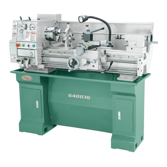
12" x 36" gunsmith’s lathe w/stand
Hide thumbs
Also See for G4003G:
- Owner's manual (72 pages) ,
- Parts list (21 pages) ,
- Owner's manual (76 pages)
Table of Contents
Advertisement
Quick Links
MODEL G4003G
12" X 36" GUNSMITH'S LATHE
w/STAND
OWNER'S MANUAL
(For models manufactured since 1/15)
COPYRIGHT © MAY, 2007 BY GRIZZLY INDUSTRIAL, INC., REVISED MAY, 2018 (HE)
WARNING: NO PORTION OF THIS MANUAL MAY BE REPRODUCED IN ANY SHAPE
OR FORM WITHOUT THE WRITTEN APPROVAL OF GRIZZLY INDUSTRIAL, INC.
#CRTRTSMN9327 PRINTED IN CHINA
V3.05.18
Advertisement
Table of Contents

Related Manuals for Grizzly G4003G


Summary of Contents for Grizzly G4003G
- Page 1 OWNER'S MANUAL (For models manufactured since 1/15) COPYRIGHT © MAY, 2007 BY GRIZZLY INDUSTRIAL, INC., REVISED MAY, 2018 (HE) WARNING: NO PORTION OF THIS MANUAL MAY BE REPRODUCED IN ANY SHAPE OR FORM WITHOUT THE WRITTEN APPROVAL OF GRIZZLY INDUSTRIAL, INC.
- Page 2 This manual provides critical safety instructions on the proper setup, operation, maintenance, and service of this machine/tool. Save this document, refer to it often, and use it to instruct other operators. Failure to read, understand and follow the instructions in this manual may result in fire or serious personal injury—including amputation, electrocution, or death.
-
Page 3: Table Of Contents
Table of Contents INTRODUCTION ..........2 Spindle Speed..........47 Machine Description ........2 Power Feed..........48 Contact Info............ 2 End Gears ............ 51 Manual Accuracy ........... 2 Threading ............. 52 Identification ........... 3 SECTION 5: ACCESSORIES ......55 Basic Controls ..........4 Machine Data Sheet ........ -
Page 4: Introduction
INTRODUCTION Machine Description Manual Accuracy The Model G4003G 12" x 36" Gunsmith’s Lathe We are proud to provide a high-quality owner’s allows you to turn and chamber gun barrels. The manual with your new machine! included outboard spindle “spider” support and tailstock with ⁄... -
Page 5: Identification
Steady Rest BB. Stand Mounting Points M. Cross Feed Handwheel CC. Thread Dial N. LED Work Light DD. Half Nut Lever O. Follow Rest EE. Apron Feed Selection Lever P. Quick-Change Tool Post FF. Carriage Handwheel Model G4003G (Mfd. Since 1/15) -
Page 6: Basic Controls
Figure 1. Headstock and quick-change gearbox controls. K. Inch Threading Chart: Displays the neces- sary configuration of gearbox levers and end gears for inch threading options. Model G4003G (Mfd. Since 1/15) - Page 7 The rotational speed of these components depends not only on the end gear configuration, but the spindle speed as well. Model G4003G (Mfd. Since 1/15)
-
Page 8: Machine Data Sheet
Machine Data Sheet MACHINE DATA SHEET Customer Service #: (570) 546-9663 · To Order Call: (800) 523-4777 · Fax #: (800) 438-5901 MODEL G4003G 12" X 36" GUNSMITHING LATHE WITH STAND Product Dimensions: Weight................................1213 lbs. Width (side-to-side) x Depth (front-to-back) x Height..............61 x 26 x 54-1/2 in. - Page 9 The information contained herein is deemed accurate as of 5/17/2018 and represents our most recent product specifications. Model G4003G PAGE 2 OF 3 Due to our ongoing improvement efforts, this information may not accurately describe items previously purchased. Model G4003G (Mfd. Since 1/15)
- Page 10 Fluid Capacities Headstock Capacity..........................3.5 qt. Headstock Fluid Type..............ISO 32 (eg. Grizzly T23963, Mobil DTE Light) Gearbox Capacity........................... 1 – 2 Pumps Gearbox Fluid Type............. ISO 68 (SB1365, Grizzly T23962, Mobil Vactra 2) Apron Capacity............................0.5 qt. Apron Fluid Type................ISO 68 (eg. Grizzly T23962, Mobil Vactra 2) Other Specifications: Country of Origin ..............................
-
Page 11: Section 1: Safety
Everyday ery. Never operate under the influence of drugs or eyeglasses are NOT approved safety glasses. alcohol, when tired, or when distracted. Model G4003G (Mfd. Since 1/15) - Page 12 EXPERIENCING DIFFICULTIES. If at any time debris. Make sure they are properly installed, you experience difficulties performing the intend- undamaged, and working correctly BEFORE ed operation, stop using the machine! Contact our operating machine. Technical Support at (570) 546-9663. -10- Model G4003G (Mfd. Since 1/15)
-
Page 13: Additional Safety For Metal Lathes
CLEARING CHIPS. Metal chips can be razor MEASURING WORKPIECE. To reduce risk of sharp. Avoid clearing them by hand or with a rag. Use a brush or vacuum instead. entanglement, never measure rotating workpieces. -11- Model G4003G (Mfd. Since 1/15) -
Page 14: Additional Chuck Safety
Always disconnect the lathe from power additional training from an experienced chuck user before performing these procedures. before using a chuck. -12- Model G4003G (Mfd. Since 1/15) -
Page 15: Section 2: Power Supply
To reduce the risk of these hazards, avoid over- loading the machine during operation and make sure it is connected to a power supply circuit that meets the specified circuit requirements. -13- Model G4003G (Mfd. Since 1/15) -
Page 16: Grounding Instructions
Minimum Gauge Size ......14 AWG be performed by an electrician or qualified Maximum Length (Shorter is Better)..50 ft. service personnel, and it must comply with all local codes and ordinances. -14- Model G4003G (Mfd. Since 1/15) -
Page 17: Section 3: Setup
IMPORTANT: Save all packaging materials until you are completely satisfied with the machine and have resolved any issues between Grizzly or the shipping agent. You MUST have the original pack- aging to file a freight claim. It is also extremely helpful if you need to return your machine later. -
Page 18: Inventory
U. Carbide Tipped Dead Center MT#3 ... 1 lost in packaging materials while unpack- Live Center MT#3 ........1 ing or they are pre-installed at the factory. W. Phillips & Flat Screwdrivers #2 ....1 Ea -16- Model G4003G (Mfd. Since 1/15) -
Page 19: Cleanup
Figure 8. T23692 Orange Power Degreaser. off the rest with the rag. Repeat Steps 2–3 as necessary until clean, then coat all unpainted surfaces with a quality metal protectant to prevent rust. -17- Model G4003G (Mfd. Since 1/15) -
Page 20: Site Considerations
Shadows, glare, or strobe effects that may distract access restricted location. or impede the operator must be eliminated. Wall 30" Minimum Clearance for Maintenance Keep Workpiece 26" Loading Area Unobstructed ⁄ " Not to Scale Figure 9. Minimum working clearances. -18- Model G4003G (Mfd. Since 1/15) -
Page 21: Assembly
Figure 11. Front panel installed. Assembling the Model G4003G consists of build- ing the stand assembly, attaching the handwheel Recommended: Use the mounting holes handles, placing and securing the lathe on the (approximately ⁄... - Page 22 Note: When the lathe is placed onto the chip pan the silicone will form a protective seal to help prevent fluid leaking into the cabinets. 13. Place lathe on stand while aligning mounting holes in lathe bed with holes in chip pan. -20- Model G4003G (Mfd. Since 1/15)
- Page 23 6mm flat washers through pedestals and chip pan, then thread them into cabinet tops. Note: For best results, recheck the ways in 24 hours to make sure they are still level and have not twisted. Reshim as required. -21- Model G4003G (Mfd. Since 1/15)
-
Page 24: Leveling
Grizzly. Lag Screw Flat Washer Machine Base Lag Shield Anchor Concrete Drilled Hole Figure 18. Popular method for anchoring machinery to a concrete floor. Figure 17. Model H2683 Master Machinist's Level. -22- Model G4003G (Mfd. Since 1/15) -
Page 25: Lubricating Lathe
Extension Cords on Page 14 for more infor- mation. Note: If this lathe was shipped with oil in the headstock and apron reservoirs, do not change that oil until after the test run and spindle break-in procedures. -23- Model G4003G (Mfd. Since 1/15) - Page 26 Circuit to those terminals. Requirements for 220V on Page 13. Ground Power Source Figure 20. Incoming power wires connected inside electrical cabinet. -24- Model G4003G (Mfd. Since 1/15)
-
Page 27: Test Run
(see Figure 21). Rotate Emergency Stop/RESET button clock- wise so it pops out. The power lamp on con- trol panel should illuminate. -25- Model G4003G (Mfd. Since 1/15) - Page 28 — Investigate and correct strange or unusual noises or vibrations before operating the machine further. Always disconnect the machine from power when investigating or correcting potential problems. -26- Model G4003G (Mfd. Since 1/15)
-
Page 29: Spindle Break-In
Run spindle at 70 RPM for 10 minutes in each direction (first forward and then reverse). Turn lathe OFF. Move spindle speed levers to C and 1 for 200 RPM, and run lathe for 5 minutes in each direction. -27- Model G4003G (Mfd. Since 1/15) -
Page 30: Section 4: Operations
Read books/magazines or get stop, then removes workpiece. formal training before beginning any proj- ects. Regardless of the content in this sec- tion, Grizzly Industrial will not be held liable for accidents caused by lack of training. -28- Model G4003G (Mfd. Since 1/15) -
Page 31: Chuck & Faceplate Mounting
Plywood Chuck Cradle Plywood Chuck Cradle (Straight Cuts) (Curved Cuts) LARGE, VERY HEAVY CHUCKS Fabricated Steel Pre-Threaded Hole Lifting Hook for Lifting Eye Figure 23. Examples of common devices used during chuck installation and removal. -29- Model G4003G (Mfd. Since 1/15) -
Page 32: Chuck Installation
CORRECT INCORRECT INCORRECT INCORRECT Stud Too High: Stud Too Low: Turn In Turn Out One-Turn One-Turn Figure 24. Inserting camlock studs into spindle cam holes. Figure 26. Correcting an improperly installed stud. -30- Model G4003G (Mfd. Since 1/15) -
Page 33: Chuck Removal
Figure 27. Registration mark locations. — If chuck does not immediately come off, rotate it approximately 60° and tap it again. Make sure all marks on cams and spindle are properly aligned for removal. -31- Model G4003G (Mfd. Since 1/15) -
Page 34: Scroll Chuck Clamping
Bar Stock Figure 30. Reversing the chuck jaws. Unsafe Jaw Position CORRECT INCORRECT Unsafe Jaw Position Safer Inside Jaw Use Cylinder Poor Scroll CORRECT Gear Engagement INCORRECT Figure 29. Jaw selection and workpiece holding. -32- Model G4003G (Mfd. Since 1/15) -
Page 35: 4-Jaw Chuck
With help from another person or a holding device, position workpiece so it is centered in chuck. Figure 32. Generic picture of non-cylindrical workpiece correctly mounted on the 4-jaw chuck. -33- Model G4003G (Mfd. Since 1/15) -
Page 36: Faceplate
To reduce this risk, use minimum of THREE Clamp independent clamping devices to hold workpiece onto faceplate. Faceplate Figure 33. Generic picture of workpiece clamped in a faceplate. -34- Model G4003G (Mfd. Since 1/15) -
Page 37: Tailstock
Positioning Tailstock Rotate tailstock lock lever clockwise (facing machine) to unlock tailstock from bedways. Slide tailstock to desired position by pushing it along the bedways. Rotate tailstock lock lever counterclockwise to lock tailstock against bedways. -35- Model G4003G (Mfd. Since 1/15) -
Page 38: Installing Tooling
Otherwise, removal of such tooling Figure 37. Drift key slot in the side of the quill. may be difficult. -36- Model G4003G (Mfd. Since 1/15) -
Page 39: Offsetting Tailstock
Use another piece of round stock to make a dead center. Turn it to a 60° point, as illus- trated below. Turn Turn Turn Turn Figure 39. Turning a dead center. Figure 38. Set screw adjustment in relation to tailstock movement. -37- Model G4003G (Mfd. Since 1/15) - Page 40 ⁄ the dis- tance of taper amount, as shown below. Move tailstock toward front of lathe amount of taper. Looking down from above. Figure 41. Adjust tailstock toward the operator. -38- Model G4003G (Mfd. Since 1/15)
-
Page 41: Centers
Lathe wear and maximize smooth operation. Using low spindle speeds will also reduce the heat and wear from friction. Figure 44. Example photo of using a dead center with a faceplate and lathe dog. -39- Model G4003G (Mfd. Since 1/15) -
Page 42: Removing Center From Spindle
Thoroughly clean and dry tapered mating surfaces of tailstock quill bore and center, Figure 46. Drift key slot in the side of the quill. making sure that no lint or oil remains on tapers. -40- Model G4003G (Mfd. Since 1/15) -
Page 43: Joining Drill Chuck & Arbor
Figure 48. Tapping drill chuck/arbor on block of wood. Attempt to separate drill chuck and arbor by hand —if they separate, repeat Steps 3–4. -41- Model G4003G (Mfd. Since 1/15) -
Page 44: Steady Rest
Note: To reduce the effects of friction, lubricate the fingers with way oil during operation. Position steady rest with base clamp where required to properly support workpiece, then tighten hex nut shown in Figure 49 to secure it in place. -42- Model G4003G (Mfd. Since 1/15) -
Page 45: Follow Rest
Tools Needed Hex Wrench 3mm ..........1 Finger Hex Wrench 6mm ..........1 Rollers Carriage Compound Rest Lock Lock Screws Cross Slide Lock Figure 51. Follow rest attachment. Figure 52. Location of compound rest lock. -43- Model G4003G (Mfd. Since 1/15) -
Page 46: Compound Rest
DO NOT extend a cutting tool more than 2.5 times the width of its cross-section (e.g., 2.5 x 0.5" = 1.25"). -44- Model G4003G (Mfd. Since 1/15) - Page 47 For this to work, the tailstock must be aligned to the spindle centerline (refer to Aligning Tailstock To Spindle Centerline on Page 37 for detailed instructions). -45- Model G4003G (Mfd. Since 1/15)
-
Page 48: Spider
0.001" (0.02mm) increments. One workpiece and leaving the jam nuts loose is not full revolution of the handwheel moves the slide safe. Spiders screws that loosen during operation 0.100" (2.54mm). can crash into the end gear cover. -46- Model G4003G (Mfd. Since 1/15) -
Page 49: Spindle Speed
Also, there are a large number of easy-to-use spindle speed calculators that can be found on the internet. These sources will help you take into account the applicable variables in order to deter- mine the best spindle speed for the operation. -47- Model G4003G (Mfd. Since 1/15) -
Page 50: Power Feed
Figure 62. Setting the spindle speed to 600 are engaged at the same time, machine RPM. damage could occur. Even though there is a lock-out device to prevent this, it could break if forced. -48- Model G4003G (Mfd. Since 1/15) -
Page 51: Power Feed Controls
Note: When using this lever, you may need to slightly rotate the handwheel of the com- ponent you are trying to engage, so that the apron gears can mesh. Figure 63. Headstock and quick-change gearbox controls for power feed. -49- Model G4003G (Mfd. Since 1/15) -
Page 52: Setting Power Feed Rate
Page 51 for detailed instructions). Note: The top half of the chart displays feed rates in mm/rev., while the bottom half dis- plays feed rates in in./rev. Figure 67. Example photo of gearbox lever pins seated in holes. -50- Model G4003G (Mfd. Since 1/15) -
Page 53: End Gears
Hex Wrench 3mm ..........1 Hex Wrench 5mm ..........1 Re-install end gear cover. Wrench or Socket 17mm ........1 To change end gears: DISCONNECT MACHINE FROM POWER! Remove end gear cover. -51- Model G4003G (Mfd. Since 1/15) -
Page 54: Threading
Half Nut Lever Lever End Gear Configuration Figure 70. End gear and gearbox lever configuration for 13 TPI. Cross Slide Disengaged Disengaged Carriage Halfnut Lever Feed Selection Engaged Lever Figure 71. Apron threading controls. -52- Model G4003G (Mfd. Since 1/15) - Page 55 1–8 1–8 setting to resume the cut as in the previous pass. 1-2-3-4 1–8 1–8 1, 3 1-2-3-4 1–8 1–8 Figure 74. Thread dial chart. -53- Model G4003G (Mfd. Since 1/15)
- Page 56 1, 3 complete. Stop the spindle at the end of each cut, retract the cutting tool, and return the cutting tool to the start of the thread. SCALE SCALE -54- Model G4003G (Mfd. Since 1/15)
-
Page 57: Section 5: Accessories
Armor Plate To reduce this risk, only install accessories grease is entirely unique due to the fact that the recommended for this machine by Grizzly. moly in it is solubilized, which provides superior performance compared to other greases contain- NOTICE ing the black solid form of molybdenum disulfide. - Page 58 ", drill G5701 G5704 G5705 diameter ⁄ ", overall length 2 ⁄ " G5703 G5700 G5699 Figure 82. Quick-change tool holders. Figure 84. T24512 6-Piece Center Drill Set. www.grizzly.com 1-800-523-4777 order online at or call -56- Model G4003G (Mfd. Since 1/15)
- Page 59 3 directions: vertical, horizontal, and angular, as required for proper performance of any floating reamer. Figure 89. T10720 Crown Savers. Figure 87. T10667 Bald Eagle Reamer Holder MT#3. www.grizzly.com 1-800-523-4777 order online at or call -57- Model G4003G (Mfd. Since 1/15)
- Page 60 " and includes a single lock knob for easy set-ups. Includes 2 dovetail tool posts and a protective plastic case. Figure 93. H7991 Mini Mag Base Indicator Set. Figure 91. H6095 Digital Readout. www.grizzly.com 1-800-523-4777 order online at or call -58- Model G4003G (Mfd. Since 1/15)
- Page 61 T10556—Taper Attachment for Model G4003G H8396—Chambering a Championship Match The Model T10556 Taper Attachment provides Barrel DVD precision outside and inside tapers up to 12" with- This video will show you how to setup and maintain out having to offset the tailstock or disengage the tight tolerances during the chambering process as cross slide.
-
Page 62: Section 6: Maintenance
(especially • Ensure carriage lock bolt is loose. parts that are exposed to water-soluble cutting fluid). Use way oil to prevent corrosion (see Page 60 for an offering from Grizzly). -60- Model G4003G (Mfd. Since 1/15) -
Page 63: Lubrication
Lubrication Headstock Oil Type ..Grizzly T23963 or ISO 32 Equivalent Oil Amount .......... 3.5 Quarts Check/Add Frequency ......... Daily Use the information in the charts below as a Change Frequency ....... Semi-Annually daily guide for lubrication tasks. We recommend... - Page 64 Quick-Change Gearbox Adding Oil The oil fill plug is located on top of the headstock, Oil Type ..Grizzly T23962 or ISO 68 Equivalent as shown in Figure 98. Oil Amount ......2 Pumps Each Port Check/Add Frequency ......... Daily...
-
Page 65: Longitudinal Leadscrew
Apron Bedways Oil Type ..Grizzly T23962 or ISO 68 Equivalent Oil Type ..Grizzly T23962 or ISO 68 Equivalent Oil Amount .......... 0.5 Quarts Oil Amount ......... As Needed Check/Add Frequency ......... Daily Lubrication Frequency ......... Daily Change Frequency ........ Annually Before lubricating the bedways (see Figure 102), clean them with mineral spirits. -
Page 66: Ball Oilers
Ball Oilers Oil Type ..Grizzly T23963 or ISO 32 Equivalent Oil Amount ........1 or 2 Squirts Lubrication Frequency ......... Daily This lathe has 14 ball oilers that should be oiled on a daily basis before beginning operation. Refer to Figures 103–1056 for their locations. - Page 67 End Gears Lubricating DISCONNECT LATHE FROM POWER! Grease ..Grizzly T23964 or NLGI#2 Equivalent Frequency ....Annually or When Changing Remove end gear cover and all end gears shown in Figure 107. The end gears, shown in Figure 107, should...
-
Page 68: Machine Storage
Loosen or remove V-belts so they do not become stretched during storage period. (Be sure to place a maintenance note near power button as a reminder that the belts have been loosened or removed.) -66- Model G4003G (Mfd. Since 1/15) -
Page 69: Section 7: Service
2. Spindle speed or feed rate wrong for Handbook or feed/speed calculator on the internet. down under load. cutting operation. 3. Cutting tool is dull. 3. Sharpen or replace the cutting tool. -67- Model G4003G (Mfd. Since 1/15) -
Page 70: Lathe Operation
3. Gibs are out of adjustment. 3. Adjust gibs (see Page 71). cutting. 4. Dull cutting tool. 4. Replace or resharpen cutting tool. 5. Incorrect spindle speed or feed rate. 5. Use the recommended spindle speed and feed rate. -68- Model G4003G (Mfd. Since 1/15) - Page 71 8. Replace gears. Gear change levers 1. Gears not aligned inside headstock/quick- 1. Rotate spindle by hand with light pressure on the will not shift into change gearbox. lever until gear falls into place. position. -69- Model G4003G (Mfd. Since 1/15)
-
Page 72: Backlash Adjustment
Loosen set screws on compound rest face- plate several turns (see Figure 110). Cap Screw Securing Faceplate Leadscrew Nut to Cross Slide Figure 108. Location of cap screw that secures Screws the leadscrew nut. Figure 110. Compound rest backlash adjustments. -70- Model G4003G (Mfd. Since 1/15) -
Page 73: Gib Adjustment
After each adjustment, use cross slide handwheel to test cross slide movement. Repeat Steps 3–4 until cross slide move- ment is acceptable. -71- Model G4003G (Mfd. Since 1/15) -
Page 74: Saddle Gib
—To loosen gib, loosen set screws. Move carriage back and forth and repeat adjustments as necessary until gib pressure is acceptable. Hold set screws in place and tighten jam nuts. Figure 113. Location of carriage lock. -72- Model G4003G (Mfd. Since 1/15) -
Page 75: Half Nut Adjustment
It should not feel too stiff or too loose. Repeat Steps 3–5, if necessary, until you are satisfied with half nut adjustment, then re-install thread dial. -73- Model G4003G (Mfd. Since 1/15) -
Page 76: Gap Removal & Installation
Tension belts (refer to Tensioning V-Belts Hex Nut on the previous page.) (1 of 2) Secure end gear cover. Figure 118. Gap retaining fasteners. Tighten alignment pin hex nuts (see Figure 118) to draw pins from gap. -74- Model G4003G (Mfd. Since 1/15) -
Page 77: Spindle Bearing Preload
DISCONNECT MACHINE FROM POWER! Tighten preload cap screw inward until it con- tacts headstock and resistance can be felt, ⁄ -turn. then tighten it an additional -75- Model G4003G (Mfd. Since 1/15) - Page 78 (Figure 122) counterclockwise and remove it. Spanner Wrench Figure 124. Dial indicator setup. Outer Spanner Nut 10. Move carriage an additional 0.100" toward headstock. Figure 122. Loosening outer spanner nut. -76- Model G4003G (Mfd. Since 1/15)
- Page 79 If you think you have gone past the zero end- play point, unload the bearings by repeating Steps 7–8, then retighten the inner spanner nut until it has reached the zero end play position. -77- Model G4003G (Mfd. Since 1/15)
- Page 80 When repeating the procedure, rotate the inner spanner nut a little less during Step 12 in the preceding instructions. Let lathe run for 20 minutes, periodically checking temperature of spindle nose (refer to the next step). -78- Model G4003G (Mfd. Since 1/15)
-
Page 81: Section 8: Wiring
Technical Support at (570) 546-9663. The photos and diagrams included in this section are best viewed in color. You can view these pages in color at www.grizzly.com. -79- Model G4003G (Mfd. Since 1/15) -
Page 82: Electrical Cabinet Wiring Diagram
24NO 34NO 44NO Ground To Work Light To Power Source To Motor To Control Panel To Spindle Switch (Page 84) (Page 84) (Page 82) (Page 82) (Page 84) READ ELECTRICAL SAFETY -80- Model G4003G (Mfd. Since 1/15) ON PAGE 79! -
Page 83: Electrical Cabinet Wiring
Electrical Cabinet Wiring Figure 127. Electrical cabinet wiring. READ ELECTRICAL SAFETY -81- Model G4003G (Mfd. Since 1/15) ON PAGE 79! -
Page 84: Motor & Control Panel Wiring Diagrams
(Page 80) Start Capacitor 150MFD 250VAC Control Panel Power Lamp SS XD103 Power Start SS LA103 Inching (Jog) SS LA103 Emergency Stop/RESET SS LA103 To Electrical Cabinet (Page 80) READ ELECTRICAL SAFETY -82- Model G4003G (Mfd. Since 1/15) ON PAGE 79! - Page 85 Motor & Control Panel Wiring Figure 128. Motor wiring. Figure 129. Control panel wiring. READ ELECTRICAL SAFETY -83- Model G4003G (Mfd. Since 1/15) ON PAGE 79!
-
Page 86: Other Component Wiring Diagrams
220V NEMA 6-15 Plug (As Recommended) Light Socket To Electrical Cabinet (Page 80) ON/OFF Switch Work Light KCD1-A 2/8A 250V Spindle Rotation Switch To Electrical Cabinet (Page 80) READ ELECTRICAL SAFETY -84- Model G4003G (Mfd. Since 1/15) ON PAGE 79! - Page 87 Other Component Wiring Figure 130. Work light wiring. Figure 131. Spindle switch. READ ELECTRICAL SAFETY -85- Model G4003G (Mfd. Since 1/15) ON PAGE 79!
-
Page 88: Section 9: Parts
Please Note: We do our best to stock replacement parts whenever possible, but we cannot guarantee that all parts shown here are available for purchase. Call (800) 523-4777 or visit our online parts store at www.grizzly.com to check for availability. -
Page 89: Headstock Gearing
Headstock Gearing 130 164 137V2 174 141 140 138-1 136 -87- Model G4003G (Mfd. Since 1/15) - Page 90 GEAR SHAFT COVER (R) P4003G0171 GEAR 42T P4003G0135 CAP SCREW M6-1 X 16 DOG-PT P4003G0172 GEAR 23T P4003G0136 COMPRESSION SPRING P4003G0173 GEAR 47T 137V2 P4003G0137V2 SPIDER BOLT SET SCREW M10-1.5 X 30 P4003G0174 HEX NUT M10-1.5 -88- Model G4003G (Mfd. Since 1/15)
-
Page 91: Headstock Controls
Headstock Controls 201 202 1119 1120 1119-1 1119-2 1119-5 1119-4 1126 1123 1118 1117 1116 1120 1119-6 1109 1106 1108 1110 1108 1103 1115 1114 1100 1110 1104 1107 1101 1102 1111 1113 1112 -89- Model G4003G (Mfd. Since 1/15) - Page 92 1119-6 P4003G1119-6 STUD-DE M10-1.5 X 122 30RH P4003G0205 CAP SCREW M6-1 X 12 1120 P4003G1120 KNURLED KNOB M10-1.5 P4003G0206 COMBO GEAR FLAT WASHER 6MM 1123 P4003G1123 E-CLIP 15MM P4003G0207 COMBO GEAR 86T/91T 1126 P4003G1126 CAP SCREW M6-1 X 8 -90- Model G4003G (Mfd. Since 1/15)
-
Page 93: Quick-Change Gearbox
Quick-Change Gearbox -91- Model G4003G (Mfd. Since 1/15) - Page 94 ROLL PIN 4 X 30 P4003G0370 SHAFT P4003G0334 SHIFT FORK P4003G0371 SET SCREW M8-1.25 X 8 P4003G0335 CAP SCREW M6-1 X 12 P4003G0372 GEAR 15T P4003G0336 GEAR FLAT WASHER 6MM P4003G0373 GEAR 24T P4003G0337 GEAR 16T P4003G0374 SHAFT -92- Model G4003G (Mfd. Since 1/15)
-
Page 95: Apron
Apron 407V2 403V2 402V2 401V2 420-1 419-1 431 430 452A 451-1 -93- Model G4003G (Mfd. Since 1/15) -
Page 96: Apron Parts List
HANDWHEEL RETAINER P4003G0433 FEED SELECTION BRACKET P4003G0470 SET SCREW M6-1 X 20 P4003G0434 FLAT WASHER 6MM P4003G0471 KEY 5 X 5 X 20 P4003G0435 CAP SCREW M6-1 X 40 P4003G0472 SET SCREW M6-1 X 8 -94- Model G4003G (Mfd. Since 1/15) -
Page 97: Saddle & Cross Slide
P4003G0521 PHLP HD SCR M5-.8 X 14 P4003G0543 STEEL BALL 6MM P4003G0522 SADDLE GIB LEFT FRONT P4003G0544 COMPRESSION SPRING 6 X 16MM P4003G0523 SADDLE GIB CENTER FRONT P4003G0545 OIL FILL CAP 3/8 NPT PLASTIC -95- Model G4003G (Mfd. Since 1/15) -
Page 98: Compound Rest & Tool Holder
Compound Rest & Tool Holder 617A -96- Model G4003G (Mfd. Since 1/15) - Page 99 KNURLED THUMB NUT M10-1 P4003G0619 CAP SCREW M6-1 X 15 P4003G0658 SET SCREW M10-1 X 45 P4003G0620 STEEL BALL 6MM P4003G0659 SET SCREW M10-1.5 X 14 DOG-PT P4003G0621 COMPRESSION SPRING 6 X 16MM P4003G0660 TOOL HOLDER BODY -97- Model G4003G (Mfd. Since 1/15)
-
Page 100: Tailstock
P4003G0729 SET SCREW M6-1 X 30 P4003G0714 HANDWHEEL HANDLE M8-1.25 X 14 88L P4003G0731 SET SCREW M8-1.25 X 50 P4003G0715 HEX NUT M12-1.75 P4003G0732 HANDLE BASE P4003G0716 QUILL LOCK HANDLE M12-1.75 X 16 170L -98- Model G4003G (Mfd. Since 1/15) -
Page 101: Bed & Motor
806-10 P4003G0806-10 BALL BEARING 5205ZZ P4003G0822 BED RACK 806-11 P4003G0806-11 CENT SWITCH P4003G0823 RIVET 2 X 5MM NAMEPLATE, STEEL 806-12 P4003G0806-12 CONTACT PLATE P4003G0824 INFORMATION PLATE P4003G0807 SPLASH GUARD P4003G0828 MOTOR MOUNT SPACER BLOCK -99- Model G4003G (Mfd. Since 1/15) -
Page 102: Stand
836-1 P4003G0836-1 LEFT STAND DOOR 829-1 P4003G0829-1 RIGHT STAND DOOR 836A P4003G0836A LEFT STAND ASSEMBLY 829-2 P4003G0829-2 DOOR LATCH P4003G0837 FLAT WASHER 14MM 829A P4003G0829A RIGHT STAND ASSEMBLY P4003G0838 HEX BOLT M14-2 X 50 P4003G0830 PANEL BRACKET RIGHT -100- Model G4003G (Mfd. Since 1/15) -
Page 103: Feed Rod
SET SCREW M6-1 X 8 P4003G0910 COMPRESSION SPRING 7020 P4003G0922 SPINDLE SWITCH ARM P4003G0911 SPINDLE SWITCH HANDLE M10-1.5 X 16 P4003G0923 SPINDLE SWITCH BOX P4003G0912 HANDLE BRACKET P4003G0924 BUTTON HD CAP SCR M4-.7 X 45 -101- Model G4003G (Mfd. Since 1/15) -
Page 104: Machine Labels
Safety labels help reduce the risk of serious injury caused by machine hazards. If any label comes off or becomes unreadable, the owner of this machine MUST replace it in the original location before resuming operations. For replacements, contact (800) 523-4777 or www.grizzly.com. -102-... -
Page 105: Electrical Components
P4003G1215 HALOGEN WORK LIGHT ASSY 1206 P4003G1206 CONTACTOR TIANSHUI JZC3 40D 1215-1 P4003G1215-1 CORD FOR WORK LIGHT 1207 P4003G1207 GROUND TERMINAL BLOCK 1215-3V2 P4003G1215-3V2 LED BULB 12V 3W BI-PIN 1208 P4003G1208 TERMINAL BLOCK 12-POLE -103- Model G4003G (Mfd. Since 1/15) -
Page 106: Steady Rest
LOCK PIN 1313 P4003G1313 LOCK BOLT M10-1.5 X 18 1314 P4003G1314 HEX NUT M12-1.75 1315 P4003G1315 FLAT WASHER 12MM 1316 P4003G1316 CLAMP PLATE 1317 P4003G1317 T-BOLT M12-1.75 X 75 1319 P4003G1319 KNURLED THUMB KNOB M10-1.5 -104- Model G4003G (Mfd. Since 1/15) -
Page 107: Section 10: Appendix
Inch Threading Chart 1, 3 1-2-3-4 1–8 1, 3 1–8 1-2-3-4 1–8 1–8 1-2-3-4 1–8 1, 3 1–8 1–8 1–8 1-2-3-4 1–8 1, 3 1–8 1–8 1–8 1–8 1-2-3-4 1–8 1–8 1, 3 1-2-3-4 1–8 1–8 -105- Model G4003G (Mfd. Since 1/15) - Page 108 -106- Model G4003G (Mfd. Since 1/15)
-
Page 109: Warranty Card
Would you recommend Grizzly Industrial to a friend? _____ Yes _____No Would you allow us to use your name as a reference for Grizzly customers in your area? Note: We never use names more than 3 times. _____ Yes _____No 10. - Page 110 FOLD ALONG DOTTED LINE Place Stamp Here GRIZZLY INDUSTRIAL, INC. P.O. BOX 2069 BELLINGHAM, WA 98227-2069 FOLD ALONG DOTTED LINE Send a Grizzly Catalog to a friend: Name_______________________________ Street_______________________________ City______________State______Zip______ TAPE ALONG EDGES--PLEASE DO NOT STAPLE...
-
Page 111: Warranty & Returns
WARRANTY & RETURNS Grizzly Industrial, Inc. warrants every product it sells for a period of 1 year to the original purchaser from the date of purchase. This warranty does not apply to defects due directly or indirectly to misuse, abuse, negligence, accidents, repairs or alterations or lack of maintenance.