Table of Contents
Advertisement
Quick Start Guide
This guide is to assist in installing and running the inverter to verify that the drive and
motor are working properly. Starting, stopping and speed control will be from the
keypad. If your application requires external control or special system programming,
consult the VAT200 Instruction Manual supplied with your inverter.
Step 1 Before Starting the Inverter
Please review Preface and Safety Precautions (page 0-1 through 1-3) of the VAT200
Instruction Manual. Verify drive was installed in accordance with the procedures as
described in VAT200 Ambient Environment and Installation on pages 3-1 through 3-8.
If you feel this was abnormal, do not start the drive until qualified personnel have
corrected the situation. (Failure to do so could result in serious injury.)
Check inverter and motor nameplates to determine that they have the same
HP and voltage ratings. (Ensure that full load motor amps do not exceed
that of the inverter.)
Remove the terminal cover to expose the motor and power terminals.
a. Verify that AC power is wired to L1, L2, and L3 (pages 3-12).
b. Verify that Motor leads are connected to T1, T2, and T3 (pages 3-12).
(The two leads may need to be reversed if motor rotation is not correct.
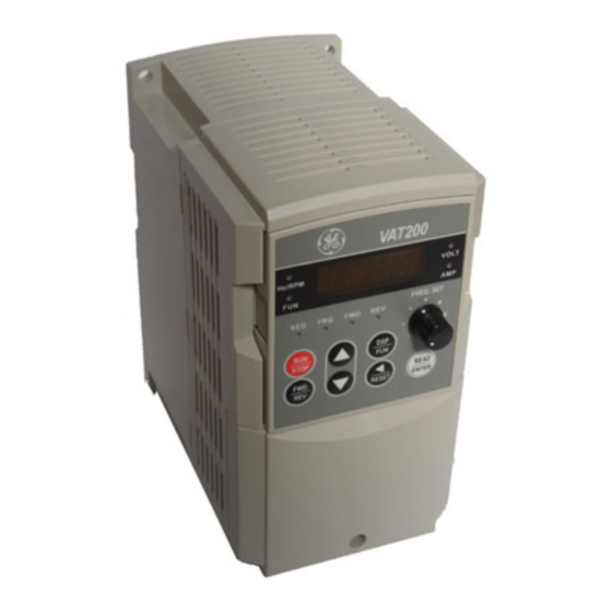
1. SEQ LED: : : : 1_00 =1, LED Lit.
2. FRQ LED: : : : 1_01 = 1/2/3/4, LED Lit
3. FWD LED: : : : Forward Direction, LED action(Flash in stop, Keep Lit in operation).
4. REV LED: : : : Reverse Direction, LED action(Flash in stop, Keep Lit in operation).
5. Four action of FUN、 、 、 、 Hz/RPM、 、 、 、 VOLT、 、 、 、 AMP LED and display of four 7-segment
display, refer to operation description of the keypad.
6. LCD keypad without FUN, Hz/RPM, VOLT, AMP LED.
i
Advertisement
Table of Contents
Troubleshooting

Related Manuals for GE VAT200


Summary of Contents for GE VAT200
- Page 1 VAT200 Instruction Manual supplied with your inverter. Step 1 Before Starting the Inverter Please review Preface and Safety Precautions (page 0-1 through 1-3) of the VAT200 Instruction Manual. Verify drive was installed in accordance with the procedures as described in VAT200 Ambient Environment and Installation on pages 3-1 through 3-8.
- Page 2 Press RUN key. Check drive acceleration to full speed. Press STOP key to stop drive and check deceleration. Step 5 Other Operations For information, see VAT200 Instruction Manual. Please refer to the following pages: Set Accel ..............p. 4-11 Set Decel ..............p. 4-11 Set Max Speed ............
-
Page 3: Table Of Contents
3.3.1 Notice for Wiring 3.3.2 Applicable Specification of Magnetic Contactor and Wires 3.3.3 Precautions for Peripheral Applications Specifications 3.4.1 Products Individual Specifications 3.4.2 General Specifications 3-10 Wiring Diagram VAT200 Series Inverter 3-12 Description of Terminals Troubleshooting Inverter 3-13 Outline Dimension 3-15 Chapter 4... - Page 4 Reactor Specification at DC Side Braking Resistor Digital Operator and Extension Cable EMC Filter Interface Card 6.6.1 RS-485 Interface Card 6.6.2 RS-232 Interface Card 6.6.3 Program Copy Unit App1 AppendixⅠ VAT200 Motor Internal Parameter List App2 AppendixⅡ VAT200 Parameters Setting List...
-
Page 5: Chapter 0 Preface
Should there be any problem in using the product and can not be solved with the information provided in the manual, contact your nearest GE’s distributor or our sales representatives who will be willing to help you. Please keep using GE’s products in the future. -
Page 6: Chapter 1 Safety Precautions
Chapte 1 Safety Precautions Chapter 1 Safety Precautions Before Using the Product 1.1.1 Before Power ON Caution The line voltage applied must comply with the inverter’s specified input voltage. Danger Make sure the main circuit connections are correct. L1(L), L2 and L3(N) are power-input terminals and must not be mistaken for T1, T2 and T3. -
Page 7: During Power On
Chapte 1 Safety Precautions 1.1.2 During Power ON Danger Do not plug or unplug the connectors on the inverter when electrified to avoid the control panel damage resulting from erratic transition voltage surge due to contact bounce. When momentary power loss is longer than 2 seconds (the larger of horse power, the longer of time), the inverter does not have enough storage power to control the circuit;... -
Page 8: During Operation
Chapte 1 Safety Precautions 1.1.4 During Operation Danger Do not engage or disengage the motor during operation. Otherwise, the over-current will cause the inverter to disconnect or the main circuit to burn. Danger To avoid electric shock, do not take the front cover off during electrifying The motor will restart automatically after stop when auto-restart function is on. - Page 9 Chapter2 Description of models Chapter 2 Description of models MODEL: U201N00K4FS → Inverter model I/P: AC 1 Phase → Input voltage 200~240V 50/60Hz O/P: AC 3PH 0~264V → Output specifications 1.2 KVA 3.1 A GENERAL ELECTRIC. 00K4 Series: Power Voltage: Noise Filter (1):...
-
Page 10: Chapter 3 Ambient Environment And Installation
Chapter 3 Ambient Environment and Installation Chapter 3 Ambient Environment and Installation 3.1 Environment The environment will directly affect the proper operation and the life span of the inverter, so install the inverter in an environment complying with the following conditions: Ambient temperature: -10 C - +40 C;... -
Page 11: Environmental Precautions
Chapter 3 Ambient Environment and Installation 3.2 Environmental precautions Do not use the inverter in an environment with the following conditions: Corrosive gas and liquid Oil Mist Direct sunlight Salt Wind, rain, and water Iron filings, dust Salt drops may get into Extreme low temperature Strong vibration Excessive high temperature... -
Page 12: Inflammable Materials
Chapter 3 Ambient Environment and Installation 3.3 Inflammable materials 3.3.1 Notice for wiring A. Screwdriver torque: Wiring with a screwdriver or other tools and follow the torque listed below: Securing torque Range KW Power source Nominal torque for TM1 terminal 0.4/0.75/1.5(3φ) 200-240V 0.59/0.08... - Page 13 The drive’s electronic protection circuitry is designed to clear drive output short circuits and ground faults without blowing the drive input fuses. Below table shows the VAT200 input fuse ratings. To protect the inverter most effectively, use fuses with current-limit function.
-
Page 14: Applicable Specification Of Magnetic Contactor And Wires
3.3.2 Applicable specification of magnetic contactor and wires Molded-case circuit breaker/magnetic contactor GE bears no responsibility to service for failures caused by the following conditions: (1) A molded-case circuit breaker is not installed, or an improper or overrated breaker is used, between the power source and the inverter. -
Page 15: Precautions For Peripheral Applications
Chapter 3 Ambient Environment and Installation 3.3.3 Precautions for peripheral applications: Power supply: Make sure the voltage applied is correct to avoid damaging the inverter. A molded-case circuit breaker must be installed between the AC source and the inverter Molded-case circuit breaker: Use a molded-case circuit breaker that conforms to the rated voltage and current of the inverter to control the power ON/OFF and protect the inverter. - Page 16 A noise filter in the output of the main circuit can suppress conductive noise. To prevent radiative noise, the wires should be put in a metal pipe and distance from signal lines of other control machines for more than 30 cm. Metal Box MCCB Metal Pipe Power Supply Noise Noise VAT200 Filter Filter above Signal Wire Controller...
- Page 17 Chapter 3 Ambient Environment and Installation When the connection between the inverter and the motor is too long, consider the voltage drop of the circuit. Phase-to-phase voltage drop (V) = 3 ×resistance of wire ( /km)×length of line (m)×current×10 . And the number of carriers must be adjusted based on the length of the line.
-
Page 18: Specifications
Chapter 3 Ambient Environment and Installation 3.4 Specifications 3.4.1 Products Individual Specifications Single phase, 200-240V model Model: U201N □ □□□ 00K4 00K7 01K5 02K2 Horsepower(HP) Suitable Motor Capacity(KW) 0.75 Rated Output Current(A) 10.5 Rated Capacity(KVA) S ing le Pha se : 200 ~240V +10% -15% ,50 /60H Max. -
Page 19: General Specifications
Chapter 3 Ambient Environment and Installation 3.4.2 General Specifications VAT200 TYPE Item Control Mode V/F or Current Vector Control Range 0.1~650.0 Hz Start control torque 150%/1Hz (Current Vector) Speed control range 1:50 (Current Vector) Speed Control Precision ±0.5% (Current Vector) Setting resolution Digital:0.01Hz( Note *1 );Analog: 0.06Hz/ 60Hz(10bits) - Page 20 Chapter 3 Ambient Environment and Installation Item VAT200 TYPE Communication Control 1. Control by RS232 or RS485 2. One to one or One to more (RS485 ONLY) control. 3. BAUD RATE/STOP BIT/PARITY/bit can be set Braking Torque About 20﹪, the model built-in braking transistor and connected...
-
Page 21: Wiring Diagram Vat200 Series Inverter
Chapter 3 Ambient Environment and Installation 3.5 Wiring diagram VAT200 series inverter Braking reactor Resistor (note1) Magnetic Molded-case circuit breaker contactor Induction motor Power Power input output Power source 200v: Class 3 ground 400v: Special ground Burst absorber Digital control... -
Page 22: Description Of Terminals Troubleshooting Inverter
3 (refer to VAT200 wiring diagram) of SW1 when used PNP input Common contact and analog input /output signal for S1~S5in NPN (Sink) input. Short-circuit pin 2 and pin 3 (refer to VAT200 wiring diagram) of SW1 when used NPN input The positive analog output for multifunction (refer to 8-00 description), the signal for output terminal is 0-10VDC (below 2mA). - Page 23 Chapter 3 Ambient Environment and Installation Symbol Function Description Multifunction input terminals(refer to 5-00 ~ 5-04 description) (S5 = Encoder input terminal, the Encoder voltage range: 19.2V~24.7V) Multifunction input terminals (Digital terminal H level:>8V, L level:<2V, PNP only) or analog input terminal AI2(0~10Vdc/4~20mA)( refer to 5-05 description) SW function Descriptions of SW2/SW3...
-
Page 24: Outline Dimension
Chapter 3 Ambient Environment and Installation 3.7 Outline Dimensions (1) Frame1:Single phase models U201__: N00K4, N00K7. Three phase models U203__: N00K4, N00K7, N01K5, X00K7, X01K5. (2) Frame2:Single phase models U201__: N01K5, N02K2. Three phase models U203__: N02K2, N04K0, X02K2, X04K0. Unit : mm/inch LENGTH MODEL... - Page 25 Chapter 3 Ambient Environment and Installation (3) Frame3:Three phase models U203__: N05K5, N07K5, X05K5, X07K5, X11K0. Unit : mm/inch LENGTH MODEL Frame 3 260/10.24 244/9.61 173/6.81 186/7.32 195/7.68 188/7.4 3-16...
- Page 26 Chapter 3 Ambient Environment and Installation (4) Frame4:Three phase models U203__: X15K0, X18K5, X22K0 (5) Frame5:Three phase models U203__: X30K0, X37K0 (6) Frame6:Three phase models U203__: X45K0, X55K0 (Open Chassis Type-IP00) Unit : mm/inch LENGTH MODEL Frame4 360/14.2 340/13.4 10/0.4 245/9.6 265/10.4 247.5/9.7 Frame5...
-
Page 27: Chapter 4 Software Index
Chapter 4 Software Index Chapter 4 Software Index 4.1 Keypad Description 4.1.1Keypad Display and Operation Instruction 1. SEQ LED:1_00 =1/2/3, LED Lit. 2. FRQ LED:1_06 = 1/2/3/4, LED Lit 3. FWD LED:Forward Direction, LED action(Flash in stop, Keep Lit in operation). 4. -
Page 28: Operation Instruction Of The Keypad
Chapter 4 Software Index 4.1.2 Operation Instruction of the keypad ● LED Light Lit Power On :LED Light Flash Power Voltage (*1) 5 second later or Enter operation signal or Press DSP to modify frequency. Frequency/Speed v < Frequency/Speed/ HZ/RPM /Line Speed HZ/RPM Line Speed... -
Page 29: Operation Instruction Of The Led Keypad
Chapter 4 Software Index 4.1.3 Operation Instruction of the LED keypad Power On ● : LED Light Lit : LED Light Flash 5 seconds later or Enter operation signal or Press DSP to modify the display frequency. ‧ HZ/RPM < < < < ‧... -
Page 30: Operation Instruction Of The Lcd Keypad
Chapter 4 Software Index 4.1.4 Operation Instruction of the LCD keypad Power On Power Source 220 V 5 second later or Enter operation signal or Press DSP to modify frequency Master Freq. < < < < Setting Freq. 60.00 Hz 060.00Hz RUN/STOP READ/... -
Page 31: Keypad Operating Example
Chapter 4 Software Index 4.1.5 Keypad Operating Example... - Page 32 Chapter 4 Software Index Example4. Modify the Frequency in Operating Example4. Modify the Value of Parameter Example 5. Operation Control 6-00 6-00 STOP STOP ● FWD LED ● REV LED ● : LED Lit : LED Flash : LED Go Out...
-
Page 33: Control Mode Selection
4. When parameter 0-00 does set to 2, the keypad will display ‘Err2’ in performing Auto tuning. 5. When VF control, 0-01~0-05 max. & min. value by the GE standard motor specification limit(one more & one less level). When VF control, no district. -
Page 34: Vat200 Programmable Functions List
Chapter 4 Software Index 4.3 VAT200 Programmable Functions List Parameter Description Group No. Drive Operation Mode Start/Stop and Frequency Control Modes Manual/Automatic Restart Modes Operating Parameters Digital Display Operation Mode Multifunction Input Terminals (MFIT) Jog, and Preset (MFIT) Speed Setting on Keypad... - Page 35 Chapter 4 Software Index 0- Drive Operation Mode Function Factory LCD Display Description Range/Code Remarks Code No. Setting 0000: Vector (General Purpose) 0001: Vector (Variable Torque) 0-00 (Control Mode) Control Mode 0000 0002: Volts/Hz (Refer to Parameter Group 10- Volts/Hz Mode) 0-01 (Motor Rated Volt) Motor Rated Voltage (Vac) -----...
- Page 36 Chapter 4 Software Index 0000: Keypad 0001: Potentiometer on Keypad 0002: External Analog Signal Input or Remote Potentiometer 0003: Up/Down Frequency Frequency Command Source 1-06 (Frequency Source) Control Using MFIT (S1 - 0000 Selection 0004: Communication setting frequency 0005: Inpulse (S5) setting frequency (ver2.3) 0000: ‘Enter’...
- Page 37 Chapter 4 Software Index 3- Operating Parameters Function Factory Description Range/Code Remarks Code No. Display Setting 50.00 / 3-00 (Freq Upper Limit) Frequency Upper Limit (Hz) 0.01 - 650.00 60.00 3-01 (Freq Lower Limit) Frequency Lower Limit (Hz) 0.00 - 650.00 0.00 Acceleration Time # 1 3-02...
- Page 38 Chapter 4 Software Index Center Frequency (CF) of 3-23 (Center F of Trav) 5.00 – 100.00 20.00 Traverse Run (%) Amplitude (A) of Traverse Run 3-24 (Amplit of Trav) 0.1 – 20.0 10.0 3-25 (Drop of Trav) Drop (D) of Traverse Run (%) 0.0 –...
- Page 39 Chapter 4 Software Index 5- Multifunction Input Terminals (MFIT) Function Factory Description Range/Code Remarks Code No. Display Setting 0000: Forward/Stop Command * 0001: Reverse/Stop Command * 5-00 (MFIT S1 Sel) Multifunction Input Term. S1 0000 0002: Preset Speed # 1 (6-02) 0003: Preset Speed # 2 (6-03) 0004: Preset Speed # 3 (6-05) * 0005: Jog...
- Page 40 Chapter 4 Software Index 0000: When the MFITs are Programmed for Up/Down Frequency Control, the Set Frequency will remain when the Drive stops. And when the Drive stops, Up/Down Function Disabled. 0001: Up/Down is used. The preset 5-08 (Stop Sel by MFIT) Stop Mode Using MFIT frequency is reset to 0 Hz as 0000 the inverter stops.
- Page 41 Chapter 4 Software Index ※ Notes: Group 7 is available when 5-06=0023 (AIN term.=Analog input 8- Multifunction Output Relays and Output Signal Operation Function Factory Description Range/Code Remarks Code No. Display Setting 0000: Output Frequency 0001: Frequency Setting Analog Output Voltage Mode 0002: Output Voltage 8-00 (AO Mode Sel)
- Page 42 Chapter 4 Software Index 0000: Enable Trip Prevention in Run Trip Prevention Selection in Mode 9-04 (Trip RUN Sel) 0000 Run Mode 0001: Disable Trip Prevention in Run Mode Trip Prevention Level In Run 9-05 (Trip Run Level) 50 - 300 Mode (%) 0000: Trip Prevention Deceleration Trip Prevention Deceleration...
- Page 43 Chapter 4 Software Index 10- Volts/Hz Operation Mode Function Factory Description Range/Code Remarks Code No. Display Setting 10-0 (V/F Selection) Volts/Hz Patterns 0 - 18 *4*6 Volts/Hz Curve Modification 10-1 (Torque Boost) 0 – 30.0 *1*6 (Torque Boost) (%) Motor No Load Current 10-2 (Motor noLoad Amp) -----...
- Page 44 Chapter 4 Software Index 12- PID "Limits" and "Out of Range" Mode Function Factory Description Range/Code Remarks Code No. Display Setting 0000: Disabled 0001: Enabled - Drive Continues to 12-0 (Fb Los Det Sel) Feedback Loss Detection Mode Operate After Feedback Loss 0000 0002: Enabled - Drive "STOPS"...
- Page 45 Chapter 4 Software Index 14- Motor Auto-Tune Parameters Function Factory Description Range/Code Remarks Code No. Display Setting 14-0 (Stator Resistor) Stator Resistance (Ohms) ----- *3*5 14-1 (Rotor Resistor) Rotor Resistance (Ohms) ----- *3*5 14-2 (Equi Inductance) Equivalent Inductance (mH) ----- *3*5 Magnetizing Current (Amps 14-3...
-
Page 46: Parameter Function Description
Chapter 4 Software Index 4.4 Parameter Function Description Parameter Group 0: Drive Operation Mode 0-00: : : : Control Mode 0000: : : : Vector mode (General Mode 0001 : : : : Vector mode VT Mode) 0002 : : : : V/F mode To select the most suitable vector control mode or V/F mode according to the load characteristics. - Page 47 Chapter 4 Software Index Parameter Group 1 - Start/Stop and Frequency Control Modes 1-00 : Run Command Source Selection 0000:Keypad 0001:External terminal control 0002:Communication control 0003:Built-in PLC 1.) 1-00=0000 the inverter is controlled by the keypad. 2.) 1-00=0001 the inverter is controlled by the external terminals, and the Stop key for emergency does work.
- Page 48 Chapter 4 Software Index 1-01 = 0002, Control mode is as below: (1). Input signal is NPN: (2). Input signal is PNP: S1 ( run ) S1 ( run ) S2 ( stop ) S2 ( stop ) S3 (FWD/REV) S3 (FWD/REV) ( 0V common ) 24V (common)
- Page 49 Chapter 4 Software Index 2.) 1-05=0001: the inverter will stop output as receiving the stop command. The motor will inertia free run to stop. 1-06 : Frequency Command Source Selection 0000: Set the Frequency with Keypad 0001: Potentiometer on Keypad 0002: External Analog Signal Input or Remote Potentiometer 0003: Up/Down Frequency Control Using MFIT (S1 - S6) 0004: Communication Setting Frequency...
- Page 50 Chapter 4 Software Index Parameter Group 2 - Manual/Automatic Restart Modes 2-00: Momentary Power Loss and Restart 0000: Momentary Power Loss and Restart Disable 0001: Momentary Power Loss and Restart is Enable 0002: Momentary Power Loss and Restart Enable while CPU is Operating. 2-01 : Momentary Power Loss Ride-Thru Time(sec): 0.0 - 2.0 second 1.) As start of the other load of power supply results in lowering the voltage below the under voltage level, the inverter will stop output at once.
- Page 51 Chapter 4 Software Index Danger: 1.) 2-05=0000 and the inverter is set external terminal controlled ( 1-00=0001 ) , if the run switch is ON as power is supplied, the inverter will auto start. It is recommend that to cut off the power switch and run switch in case of injury to persons or machine as power is resupplied.
- Page 52 Chapter 4 Software Index Parameter Group 3 - Operating Parameters 3-00: Frequency Upper limit(Hz) : 0.01 - 650.00 3-01: Frequency Lower limit(Hz) : 0.01 - 650.00 3-00 (upper frequency limit) 3-01 (lower frequency limit) ( note ) ※ Note: When 3-01 = 0 Hz and frequency command is 0 Hz , the inverter will stop at 0 speed. When 3-01 >...
- Page 53 Chapter 4 Software Index is at line. 6.)When S curve time (3-04/3-05) is larger than 0, the acceleration and deceleration action is as following diagram. 7.)Regardless of the stall prevention period, actual acceleration and deceleration time =preset acceleration / deceleration time + S curve time. For example: acceleration time = 3-03+ 3-04 。 8.)During acceleration and deceleration process, there might be residual error in acceleration and deceleration toggling.
- Page 54 Chapter 4 Software Index 3-17: Parameter lock function 0000: Enable all Functions 0001: 6-00 - 6-08 cannot be changed 0002: All Functions Except 6-00 - 6-08 cannot be changed 0003: Disable All Function 3-18: Copy Unit 0000: Disable 0001: Inverter to Copy Unit 0002: Copy Unit to Inverter 0003: Verify 1.) 3-18=0000 :...
- Page 55 Chapter 4 Software Index 2. Energy saving mode is only available under V/F mode. (0-00 = 0002) 。 3-22: : : : Carrier Frequency (KHz) : : : : 2-16 Carrier Carrier Carrier Carrier 3-22 3-22 3-22 3-22 Frequency Frequency Frequency Frequency 2KHz...
- Page 56 Chapter 4 Software Index 2) During traverse run, the center frequency could be controlled by the multifunction input terminals. However, the X up deviation and Y low D deviation can not be input at the same time. If they are input at the same time, the inverter will maintain the original center frequency.
- Page 57 Chapter 4 Software Index Parameter Group 4 - Digital Display Operation Mode 4-00: : : : Motor Current Display Selection: : : : 0000: Disable Motor Current Display 0001: Enable Motor Current Display 4-01: : : : Motor Voltage Display Selection: : : : 0000: Disable Motor Voltage Display 0001: Enable Motor Voltage Display 4-02:...
- Page 58 Chapter 4 Software Index Parameter Group 5-Multifunction Input Terminals (MFIT) Multifunction input terminals (TM2 S1-S6/AIN) controlling: : : : 5-00~06 0000: Forward/Stop Command * 0001: Reverse/Stop Command * 0002: Preset Speed # 1 (6-02) 0003: Preset Speed # 2 (6-03) 0004: Preset Speed # 3 (6-05) * 0005: Jog 0006: Acc/Dec time # 2...
- Page 59 Chapter 4 Software Index 3. 5-00~06=5(Jog) To select Jog operation as ON the external input terminals. Now, the inverter operates at the Jog acceleration and deceleration time. The corresponding frequency parameter is illustrated below: The priority order of frequency: Jog Speed → Preset Speed → Keypad frequency or external frequency signal Multifunction Multifunction...
- Page 60 Chapter 4 Software Index controlled by 1-00/01. 10. 5-00~06=12Æ Û Switch of the inverter controlling in communication External switch terminal is OFF : in communication, the master (PC or PLC) can control the inverter operation and frequency signal and allowably modify the parameters, and the operation signals from Keypad and TM2 are idle.
- Page 61 Chapter 4 Software Index (5) 5-09 ≠ 0, the inverter will accelerate to the setting of 6-00 and maintain at the speed. When the UP/Down terminal is On, setting frequency is present value 6-00 ± 5-09, and the inverter will accelerate/ decelerate to frequency 6-00. The upper frequency limit and lower frequency limit also restrict the operation.
- Page 62 Chapter 4 Software Index 19. 5-06=23 (Analog input AIN) The multifunction terminal AIN = 23. The action is provided for setting the frequency. 20. 5-00~06=24 (PLC Application) The multifunction terminal S1-AIN=24, which means the terminal is for PLC application. The terminal is provided for the PLC program input. 21.
- Page 63 Chapter 4 Software Index Step of Up/Down Function (Hz): 5-09: : : : Up/Down (Hz) 0.00 – 5.00 There are two modes covered below: (1) 5-09 = 0.00, the function is disable. The operation is just as the original one. As UP terminal is ON, the frequency increases while the DOWN terminal is ON, the frequency decreases.
- Page 64 Chapter 4 Software Index Reference Source 2: : : : 5-11 Auxiliary frequency source can be selected When frequency source command setting as impulse command , ( 1-06= 5 ) If master speed operating(5-00~5-06 setting to 16 and the terminal is OFF), frequency running as impulse frequency.
- Page 65 Chapter 4 Software Index Parameter Group 6- Jog and Preset (MFIT) Speed Setting on Keypad Jog and Preset (MFIT) Speed Setting on Keypad: : : : 6-00~08: Set Jog and preset speed by Keypad A. 5-00~06=2-4(preset speed 1~3) The external multifunction terminal = ON, the inverter operates at preset speed. The operation time of the 8 stages is base on the ON time of the terminal.
- Page 66 Chapter 4 Software Index Parameter Group 7 - Analog input signal operation mode Analog Input Signal Operation Mode: 7-00:AIN Gain(%) 0 - 200 7-01:AIN Bias(%) 0 - 100 7-02:AIN Bias Selection: 0000:positive 0001:Negative 7-03:AIN Slope: 0000:positive 0001:Negative 7-04: AIN signal verification Scan Time (AIN, AI2) 1–100 ( × 4mSec) 7-05: AI2 Gain (%)(S6) 0 –...
- Page 67 Chapter 4 Software Index Parameter Group 8 - Multifunction output terminal and output signal operation mode Multifunction analog output control: 8-00: : : : Analog Output Voltage Mode: : : : 0000: Output frequency 0001: Frequency Setting 0002: Output voltage 0003: DC Bus Voltage 0004: Motor current 0005: FEEDBACK Signal of PID...
- Page 68 Chapter 4 Software Index 8-02/03= 01: : : : The preset frequency is reached ( ± 8-05) 8-02/3= 02: : : : Arbitrary frequency consistency Fout = 8-04 ± 8-05 8-02/3 = 03: : : : frequent detection Fout > 8-04 4-42...
- Page 69 Chapter 4 Software Index 8-02/3 = 04: : : : frequent detection Fout < 8-04 8-02/3= 05: : : : over torque detection 4-43...
- Page 70 Chapter 4 Software Index Parameter Group 9 – Drive and Load Protection Modes 9-00: : : : Trip Prevention Selection During Acceleration: 0000: : : : Enable Trip Prevention During Acceleration 0001: : : : Disable Trip Prevention During Acceleration 9-01:...
- Page 71 Chapter 4 Software Index run for 1 minute. 2. The heat sinking function will declining when the motor run at low speed. So the thermal relay action level will decline at the same time.(The curve 1 will change to curve 2). 3.
- Page 72 Chapter 4 Software Index torque is less than the 9-14 setting value. = 0001 : If there is over torque, the inverter coasts to stop and flashes OL3. it is necessary to press ‘RESET’ or external terminal to continue to run. Parameter8-02,03(Multifunction output terminal ) = 05, the output terminal is output over torque signal.
- Page 73 Chapter 4 Software Index 2. 10-0 = 0 – 17 V / F Pattern (Refer to following list ) 。 type 10-0 V/F pattern type ctio 10-0 V/F pattern V (%) V (%) 2.5 50 650 Hz 0.1 3.0 60 650 Hz V (%) V (%)
- Page 74 Chapter 4 Software Index 10-0 50.0% 1.0% 0 / 9 60.0% 1.0% 1 / 10 65.0% 1.0% 2 / 11 70.0% 1.0% 3 / 12 40.0% 1.0% 4 / 13 35.0% 1.0% 5 / 14 45.0% 1.0% 6 / 15 55.0% 1.0% 7 / 16...
- Page 75 Chapter 4 Software Index Parameter group 11 - PID operation mode 11-0: : : : PID Operation Selection 0000: PID disable 0001: PID enable (Deviation is D-controlled) 0002: PID Feedback D-controlled 0003: PID D Reverse characteristic controlled 0004: PID Feedback D characteristic controlled 0005: PID, Frequency command + D controlled 0006: PID, Frequency command + Feedback D controlled 0007: PID, Frequency Command + D reverse Characteristic controlled.
- Page 76 Chapter 4 Software Index 11-7: : : : Output Lag Filter TimeÆÉ ÆÉ ÆÉÆÉ sÆÊ ÆÊ ÆÊÆÊ : : : : 0.0 - 2.5 11-7 : update time for output frequency. ※ Note: PID Function is available for controlling the output flow, external fan flow and temperature. The controlling flow is as follow: 1.
- Page 77 Chapter 4 Software Index Parameter Group 12 - PID "Limits" and "Out of Range" Mode 12-0: : : : Feedback Loss Detection Mode: 0000:Disable 0001:Enable – Drive Continues to Operate After Feedback Loss 0002:Enable – Drive “STOPS” After Feedback Loss 12-0= 0 :...
- Page 78 Chapter 4 Software Index When PID output frequency is larger than the frequency for sleep start the inverter will be awaked and enter PID awake mode. The time diagram is as follow: Parameter Group 13 - Communication mode 13-0: : : : Assigned Communication Station Number: : : : 1 - 254 13-0: to set the communication station codes which are suitable for driving more than one inverters situations.
- Page 79 .Communication format (13-2/13-3/13-4) should be set as the same. b. The inverter will confirm the parameter efficient as PC modifies the parameter of the inverter. c. Please refer to the VAT200 Communication PROTOCOL. Parameter Group 14 - Auto Tuning 14-0:...
- Page 80 Chapter 4 Software Index 15-1: : : : Software Version 15-2: : : : Fault Jog( ( ( ( Latest 3 times) ) ) ) 1. When the inverter doesn’t work normally, the former fault log stored in2.xxxx will be transferred to 3.xxxx, then, the one in 1.xxxx to 2.xxxx.
-
Page 81: Specification Description On Built-In Plc Function
Chapter 4 Software Index 4.5 Specification Description on Built-in PLC Function 7300CV has Built-in simple PLC function, user can download Ladder Diagram from PC (Windows base software) or PDA (WinCE base software) very friendly. 4.5.1 Basic Instruction NO / NC Input Instruction I1∼I7 / i1∼i7 Output Instruction... -
Page 82: Function Of Basic Instruction
Chapter 4 Software Index 4.5.2 Function of Basic Instruction ◎ Function D (d) Command Sample 1: I1─D ──[ Q1 One complete scan period Sample 2: i1─d ──[Q1 I1 is the reverse phase of i1. One complete scan period ◎ NORMAL ( - [ ) Output I1 ──... -
Page 83: Application Instructions
Chapter 4 Software Index 4.5.3 Application Instructions ◎ Counter Symbol Description Counting Mode (1-4) Use (I1 ~ f8) to set counting up or counting down OFF: counting up (0, 1, 2, 3, 4….) ON: counting down ( ….3, 2, 1, 0) Use (I1 ~ f8) to RESET the counting value ON: the counter is initialized to zero and OFF: the counter continues to count... - Page 84 Chapter 4 Software Index Sample: Input under the Ladder Program Mode The ON/OFF of C3 input count pulse I1 ─ i2 ─ -- ─﹝C3 is controlled by I1 and i2. C3 ─ -- ─ -- ─﹝Q1 ┬ -- ─ q1 ─﹝M2 ┴...
- Page 85 Chapter 4 Software Index (2) Counter Mode 2 ※Note: Under this Mode, the counting preset value appeared will be greater than 20, unlike the Mode 1 in which the value is locked at 20. (3) The counter Mode 3 is similar to the counter Mode 1 except that the former can memory the recorded value after the power is cut off and continued counting when the power is turned on at the next time.
- Page 86 Chapter 4 Software Index ◎ Timer Description Symbol Timing Mode (1-7) Timing unit 1: 0.0 – 999.9 sec 2: 0 – 9999 sec 3: 0 – 9999 min Use (I1 ~ f8) to RESET the timing value. ON: the counter is reset to zero and OFF: the counter continues to count Preset Timing Value Target (setting) Timing Values...
- Page 87 Chapter 4 Software Index Sample: Input under the Ladder Program Mode When I1 = ON, the fifth Timer starts operating I1 ─ -- ─ -- ─﹝T5 T5 ─ -- ─ -- ─﹝Q1 Input under the Function Program Mode Timing unit = 0.1 sec Timer Mode 1 ┐...
- Page 88 Chapter 4 Software Index (3) Timer Mode 3 (OFF-Delay A Mode) (4) Timer Mode 4 (OFF-Delay B Mode) 4-62...
- Page 89 Chapter 4 Software Index (5) Timer Mode 5 (Flash A Mode) (6) Timer Mode 6 (Flash B Mode) (7) Timer Mode 7 (Flash C Mode) 4-63...
- Page 90 Chapter 4 Software Index ◎ Analog comparator Symbol Description Analog comparison mode (1-3) Selection of the input comparison value Analog input value Setting reference comparison value (upper limit) Setting reference comparison value (lower limit) Output terminals of analog comparator (G1-G4) ◎Analog Comparison Mode (1-3) ≤...
- Page 91 Chapter 4 Software Index ◎ Encoder input Comparing Instruction Symbol Description Encoder control mode (1-2) Use (I1 ~ f8) to set counting up or counting down OFF: counting up (0, 1, 2, 3, 4….) ON: counting down ( ….3, 2, 1, 0) Use (I1~f8) to Reset counting value.
- Page 92 Chapter 4 Software Index Sample: Input under the Ladder Program Mode ON/ OFF of I1 controls the Run/Stop I1 ─ -- ─ -- ─﹝F1 status of F1. F1 ─ -- ─ -- ─﹝Q1 Input under the Function Program Mode ┐ ┐ ┐ ┐ 10.0 When Inverter operating, F1=ON.
-
Page 93: Chapter 5 Troubleshooting And Maintenance
Chapter 5 Troubleshooting and maintenance Chapter 5 Troubleshooting and maintenance 5.1. Error display and remedy 5.1.1. Errors which can not be recovered manually Display Error Cause Remedy Connect a parallel RC burst Program absorber across the magnetizing External noise interference problem coil of the magnetic contactor that causes interference... - Page 94 OVSP (vector mode) Parameter 3. The gain is too big during 3.Change stator Resistance gain vector mode operating and Rotator resistance gain 4. The Current detect circuit (14-0/14-1), suggest that fault decrease 50~100, until 0 4. Send back to GE...
- Page 95 Chapter 5 Troubleshooting and maintenance Errors which can be recovered manually Display Error Cause Remedy 1. Detection circuit 1.Check the noise between Power Over-current during malfunctions line and motor line stop 2. Bad connection for CT 2.Send the inverter back for signal cable repairing 1.
-
Page 96: Special Conditions
Chapter 5 Troubleshooting and maintenance Special conditions 5.1.2 Display Error Description STP0 Zero speed stop Happened when preset frequency <0.1Hz 1. If the inverter is set as external terminal control mode (1-00=1) and direct start is disabled (2-04=0001), the inverter cannot be started STP1 Fail to start directly and will flash STP1 when operation switch turned to ON after... -
Page 97: Operation Errors
Chapter 5 Troubleshooting and maintenance 5.1.3 Operation errors Display Cause Remedy Error Parameter and 1.Attempt to modify frequency 1. Set 3-17=0000 frequency /parameter while 3-17>0000 reverse already 2. Set 1-02=0000 2.Attempt to reverse while 1-02=0001 locked 1.The ▲ or▼ is 1.Press ▲... -
Page 98: General Troubleshooting
Chapter 5 Troubleshooting and maintenance 5.2 General troubleshooting Status Checking point Remedy ‧Is the power applied? Is power applied to L1(L), L2, and L3(N) ‧Turn the power OFF and then ON again. terminals (is the charging indicator lit)? ‧Make sure the power voltage is correct. ‧Make sure screws are secured firmly. - Page 99 Chapter 5 Troubleshooting and maintenance 5.3 Quick troubleshooting of VAT200 series VAT200 INV Fault Is fault fully understood? Check burnt and damaged symptoms of burn Symptoms other than burn out, damage, or fuse meltdown in parts out and damage? the inverter?
- Page 100 Chapter 5 Troubleshooting and maintenance to previous page Check parameters of inverter Perform parameter initializations Specify operation control mode FWD or REV LED Replace the control board light after flashes Set up frequency command Is the frequency value Replace the control board displayed in operation unit Are there...
- Page 101 Chapter 5 Troubleshooting and maintenance Troubleshooting for OC, OL error displays The inverter displays OC, OL errors Is the main circuit Replace I.G.B.T I.G.B.T working Any abnormalities in Replace faulty circuit board appearances? Apply the power Any abnormal Is the current detector indications? Input operation command Replace control board...
- Page 102 Chapter 5 Troubleshooting and maintenance Troubleshooting for OV, LV error The inverter displays OV, LV Replace the main circuit fuse Is the main circuit fuse intact? Replace the faulty circuit Any abnormalities in board appearances? Apply the power Any abnormal Replace the control board indications? Input operation command...
- Page 103 YES (within ±10% of the normal value) Are voltages ˙The power is abnormal between power ˙Bad wiring terminals correct? Is LED 101lit? VAT200 fault The operation switch is set to Is the operation switch “RUN’ position in “RUN’ position Are there outputs between VAT200 fault...
- Page 104 Reduce the load. Increase capacities of and the motor. VAT200 Are output voltages VAT200 faults between U-V,V-W,W-U balanced? YES (within ±3% of rated output voltage Reduce the load floating or Is the load add a flywheel. floating?
-
Page 105: Routine Inspection And Period Inspection
Chapter 5 Troubleshooting and maintenance 5.4 Routine inspection and period inspection To ensure stable and safe operations, check and maintain the inverter regularly and periodically. The table below lists the items to be check to ensure stable and safe operations. Check these items 5 minutes after the “Charge”... -
Page 106: Maintenance And Inspection
(b) Internal insulation test should be performed against the main circuit of the VAT200 body only. Use a high resistance DC 500V meter with insulating resistance higher than 5MΩ. Caution! Do not perform this test against the control circuit. -
Page 107: Peripheral Components
Chapter 6 Peripherals Components Chapter 6 Peripherals Components 6.1-6.2 Reactor specification at Input side and at DC Side AC Input Reactor DC Reactor AC Input Reactor DC Reactor VAT200 Model VAT200 Model Cat. Number Cat. Number Cat. Number Cat. Number U201N00K4... -
Page 108: Braking Resistor
Chapter 6 Peripherals Components 6.3 Braking unit and braking resistor VAT200 series braking current calculation Motor External GE Encapsulate Braking Resistor GE Tubular Braking Resistor Drive Braking Unit (s) CatNumber Dim. (mm) CatNumber Dim. (mm) U20_N00K4 ERN00K7 251*28*60 TLR200P200 210*60*65... -
Page 109: Digital Operator And Extension Cable
Chapter 6 Peripherals Components 6.4 Digital operator and extension cable A. Remote Cable Kit Inverter Model Extension Cable Kit Cable Length (Meter) U200AW05 U200AW10 All models U200AW20 U200AW30 U200AW50 B. Content Inverter LED (U200ALEDK) or LCD (U200ALCDK) Keypad REMOTE Cable for Keypad C. - Page 110 Chapter 6 Peripherals Components Unit : : : : mm LED Keypad(U200ALEDK)Mounting Dimensions Unit : : : : mm LCD Keypad(U200ALCDK)Mounting Dimensions...
-
Page 111: Emc Filter
Chapter 6 Peripherals Components 6. 5 EMC Filter The inverter adopts rapid switching components to improve the efficiency of the motor and to reduce the motor noise. Using the EMC Filter allows the EMI (Electromagnetic Interference) and RFI (Radio Frequency interference) to be controlled within certain range. EMC Directives The inverter with optional filter complies with the EMC directives 89/336/EEC, limiting the environmental EMI and RFI. - Page 112 Chapter 6 Peripherals Components VAT200 External Filter Size SIZE Inverter Mounting External Filter Size External Filter Mounting MODEL Dimensions (C*B) (W*H*D) Dimensions(E*A) U200F611TA1 U200F709TA1 78 * 150 91 * 192 * 28 74 * 181 U200F905TA1 U200F627TA2 U200F719TA2 114.6 * 170.5...
-
Page 113: Interface Card
6.6 Interface Card 6.6.1 RS-485 Interface Card ( Model : U200ARS-485 ) U200ARS-485 Wiring Diagram: : : : L1(L) THREE-PHASE POWER SUPPLY L3(N) 24 V VAT200 SERIES INVERTER U200ARS RS-485 (+) CON2 (12P) (一) ※Note: Please put on the cover of inverter to avoid the Interface Card disturbed by outside static electricity. -
Page 114: Rs-232 Interface Card
Chapter 6 Peripherals Components 6.6.2 RS-232 Interface Card (Model : U200ARS-232 ) U200ARS-232Wiring Diagram: : : : L1(L) THREE-PHASE POWER SUPPLY L3(N) VAT200 SERIES INVERTER RS-232 CON2 (12P) U200ARS- 1.8m... -
Page 115: Program Copy Unit
Chapter 6 Peripherals Components 6.6.3 Program Copy Unit (Model: U200AMP) U200AMP Wiring Diagram L1(L) THREE-PHASE POWER SUPPLY L3(N) VAT200 SERIES INVERTER CON2 (12P) U200AMP 6.6.4 PDA Link ①. HP iPAQ Pocket PC h2210. (PDA) ②. PDA wire (U200ARSPDA). ③. RS-232 Interface Card (U200ARS232). - Page 116 Appendix Appendix 1: VAT200 Motor Internal Parameter List Factory Setting of the Motor Internal Parameters: Parameter 14-0 14-1 14-2 14-3 14-4 (stator (Rotor (Equivalent (Magnetization (iron Loss Model Resistance) Resistance) Inductance) Current) Conductance) U20_ N00K4 U20_ N00K7 U20_ X00K7 U20_ N01K5...
- Page 117 Appendix Appendix 2: VAT200 parameter setting list Customer Inverter Model Using Site Contact Phone Address Parameter Setting Parameter Setting Content Parameter Setting Content Parameter Setting Code Content Code Code Code Content 0-00 3-14 6-06 10-7 0-01 3-15 6-07 10-8 0-02...