Makita JV0600 Technical Information
Hide thumbs
Also See for JV0600:
- Instruction manual (60 pages) ,
- Instruction manual (49 pages) ,
- Instruction manual (29 pages)
Advertisement
Quick Links
Download this manual
See also:
Instruction Manual
T
ECHNICAL INFORMATION
Model No.
Description
C
ONCEPT AND MAIN APPLICATIONS
Model JV0600 has been developed as a jig saw to cover
the midrange class that had not been in our range.
Its main features are:
• Compact and lightweight design has been achieved
without losing strong power nor high maneuverability
• New toolless blade clamp for quick blade changes
• Rigid aluminum support housing with blow-off device
added to protect the rod portion from saw dust for
enhanced performance against dust.
S
pecification
Voltage (V)
110
120
220
230
240
No load speed: strokes per min.
Stroke length: mm (")
Shank type
Capacities: mm (")
Cut settings
Vibration measured according to
EN60745-2-11: m/s²
Variable speed control by dial
Material of base
Housing type
Toolless blade change
Protection against electric shock
Power supply cord: m (ft)
Weight according to
EPTA-Procedure 01/2003: kg (lbs)
* When cutting with optional blade No. B-16L
S
tandard equipment
Jig saw blade No. B-10 ......... 1
Hex wrench 3 ........................ 1
Guide rule set ........................ 1 (for some countries only)
Plastic carrying case ............. 1
Note: The standard equipment for the tool shown above may differ by country.
O
ptional accessories
Guide rule set
Hose 28-1.5
Kerf board set
Hose 28-3.0
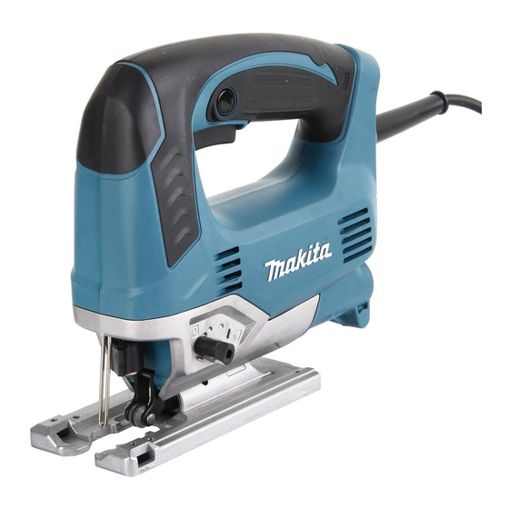
JV0600
Jig Saw
Current (A)
Cycle (Hz)
6.2
50/60
6.5
50/60
3.1
50/60
3.0
50/60
2.9
50/60
Wood*
Steel
Aluminum
Europe: 4.0 (13.1), Australia, Brazil: 2.0 (6.6),
Jig saw blades
Cover plate
Continuous Rating (W)
Input
650
---
650
650
650
500 - 3,100
23 (7/8)
B-type
90 (3-1/2)
10 (3/8)
20 (25/32)
3 Orbital settings + Straight cutting
10.5
Yes
Aluminum
Clamshell type
Yes
Double insulation
Other countries: 2.5 (8.2)
2.4 (5.2)
PRODUCT
L
H
W
Dimensions: mm (")
Length (L)
236 (9-1/4)
Width (W)
77 (3)
Height (H)
199 (7-7/8)
Max. Output (W)
Output
380
600
380
600
380
600
380
600
380
600
P 1/ 12
Advertisement

Related Manuals for Makita JV0600


Summary of Contents for Makita JV0600
- Page 1 Description Jig Saw ONCEPT AND MAIN APPLICATIONS Model JV0600 has been developed as a jig saw to cover the midrange class that had not been in our range. Its main features are: • Compact and lightweight design has been achieved without losing strong power nor high maneuverability Dimensions: mm (")
-
Page 2: Necessary Repairing Tools
Removing retaining ring S-6 from the Pin of Bearing case 1R381 Claw for 1R006 Attachment for 1R006 [2] LUBRICATIONS Apply the grease designated by Makita to the portions pointed with triangles to protect parts and product from unusual abrasion. Item No. Description Portion to lubricate... - Page 3 P 3/ 12 epair [3] DISASSEMBLY/ASSEMBLY [3]-1. Housing DISASSEMBLING (1) Remove Base section for disassembling Housing. See Fig. 2. Fig. 2 1. Inserting Slotted head screwdriver < Note in Disassembling > into the cut portion, remove Lever 8 Be careful not to lose Compression spring 4 by levering up it with the screwdriver.
- Page 4 P 4/ 12 epair [3] DISASSEMBLY/ASSEMBLY [3]-1. Housing DISASSEMBLING (2) Housing set (R) is separated from the Machine. See Fig. 3. Fig. 3 4x18 Tapping screws ( 10 ocs. ) 6. Now Housing set (R) can be separated from Housing set (L), by unscrewing ten 4x18 Tapping screws.
- Page 5 P 5/ 12 epair [3] DISASSEMBLY/ASSEMBLY [3]-2. Crank Mechanism DISASSEMBLING (3) Crank section and Armature are separated from the Housing set (L). See Fig. 5. Fig. 5 5. Remove Armature 4. Disconnect Carbon brush Armature and Crank section from Commutator. at a time.
- Page 6 P 6/ 12 epair [3] DISASSEMBLY/ASSEMBLY [3]-2. Crank Mechanism ASSEMBLING (1) Assemble Armature to Bearing case complete. Refer to the lower illustrations in Fig. 6. (2) Assemble Crank mechanism as drawn in Fig. 7. Fig. 7 1. Mount Push plate, Balance plate, Gear complete and 2.
- Page 7 P 7/ 12 epair [3] DISASSEMBLY/ASSEMBLY [3]-2. Crank Mechanism ASSEMBLING (5) Turning Armature, move Crank pin of Gear complete to the highest point from the edge of Housing set (L), for easy assembling of Slider section. Refer to the center illustration in Fig. 4. And mount slider section to Housing set (L).
- Page 8 P 8/ 12 epair [3] DISASSEMBLY/ASSEMBLY [3]-3. Slider section, Toolless Blade Clamp Mechanism DISASSEMBLING (1) Disassemble Lever 8, Base, Housing cover, Safety wire as illustrated in Fig. 2. And then, remove Housing set (R) as illustrated in Fig. 3. (2) Take out Slider section as illustrated in Fig. 4. (3) The Slider section can be disassembled as illustrated in Fig.
- Page 9 P 9/ 12 epair [3] DISASSEMBLY/ASSEMBLY [3]-3. Slider section, Toolless Blade Clamp Mechanism ASSEMBLING (1) Assemble Blade clamp mechanism as illustrated in Fig. 13. Fig. 13 1. Put Compression spring 4 3. Insert Pin 2 into 2. Mount Torsion and Lock pin into the hole the hole illustrated spring 10.
- Page 10 P 10/ 12 epair [3] DISASSEMBLY/ASSEMBLY [3]-3. Slider section, Tool less Blade Clamp Mechanism ASSEMBLING (2) Assemble Toolless mechanism to Slider (Fig.14). Fig.14 2. Assemble Slider plate to Rod. Note: Locate the closed end of Slider plate 1. Set Poly urethane sponge 3.
-
Page 11: Circuit Diagram
P 11/ 12 ircuit diagram Fig. D-1 Color index of lead wires' sheath Black Orange White Blue with Terminal Block Noise For some countries, Suppressor Noise supressor is not used. Terminal Block Controller This Lead wire is brown Switch in stead of black for some countries. -
Page 12: Wiring Diagram
P 12/ 12 iring diagram Fig. D-2 Set Brush holder to housing set L as per illustrated direction below. Note: Do not route Lead wire from Brush holder under the Brush holder itself. Housing L Opening for connecting Lead wire Housing R side Fig.