Makita BFL301F Technical Information
Cordless angle screwdriver 14.4v
Hide thumbs
Also See for BFL301F:
- Instruction manual (11 pages) ,
- Instruction manual (49 pages) ,
- Instruction manual (52 pages)
Table of Contents
Advertisement
Quick Links
Download this manual
See also:
Instruction Manual
T
ECHNICAL INFORMATION
Model No.
Description
C
ONCEPT AND MAIN APPLICATIONS
These cordless angle screwdrivers for fastening works in assembling line
are developed as advanced models of BFL300F, BFL400F.
Additionally to the same tool durability and high fastening torque accuracy
as the current series models, these products feature a powerful and efficient
power source and power unit, namely 14.4V/ 3.0Ah Li-ion battery* and
BLDC motor (Brushless DC motor).
*Compatible with BL1430 and BL1430A but not with 1.3Ah Li-ion battery BL1415
These products are available in the following specifications
with the model numbers described below.
S
pecification
Specifications
Voltage: V
Capacity: Ah
Battery
Cell
Max output: W
Fastening torque range: N.m (in.lbs)
No load speed: rpm= min
Driving shank: mm (")
Soft start
LED Job light
Electric brake
Reversing switch
Torque adjustment
Weight according to
EPTA-Procedure 01/2003*: kg (lbs)
* with Battery BL1430
S
tandard equipment
No
Note: The standard equipment for the tool shown above may vary by country.
O
ptional accessories
Battery BL1430
Battery BL1430A
Fast charger DC18RA
Charger DC18SD
Charger DC24SC
Automotive Charger DC18SE
BFL301F, BFL402F
Cordless Angle Screwdriver 14.4V
Model
16 - 30 (142 - 266)
-1
Auto refresh adapter ADP03
Battery protector (for BL1430A)
Protectors (red/ blue/ yellow/ clear)
Torque adjust tool
BFL301F
14.4
3.0
Li-ion
315
260
9.5 (3/8) Square
Yes
Yes
Yes
Yes
Yes
2.0 (4.4)
L
Dimensions: mm (")
Model No.
BFL301F
Length (L)
Width (W)
Height (H)
BFL402F
370
25 - 40 (221 - 354)
200
PRODUCT
P 1/ 14
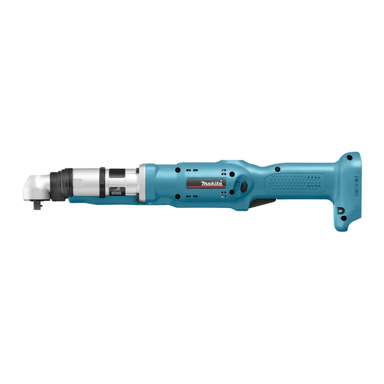
H
W
(model BFL301F)
BFL402F
477 (18-3/4)
72 (2-13/16)
98 (3-7/8)
Advertisement
Table of Contents

Related Manuals for Makita BFL301F


Summary of Contents for Makita BFL301F
- Page 1 ECHNICAL INFORMATION PRODUCT P 1/ 14 BFL301F, BFL402F Model No. Description Cordless Angle Screwdriver 14.4V ONCEPT AND MAIN APPLICATIONS These cordless angle screwdrivers for fastening works in assembling line (model BFL301F) are developed as advanced models of BFL300F, BFL400F. Additionally to the same tool durability and high fastening torque accuracy Dimensions: mm (")
- Page 2 CAUTION: Repair the machine in accordance with “Instruction manual” or “Safety instructions”. Note: Some parts numbers and descriptions differ from model to model. Refer to the following list and replace the descriptions in this technical information. Model No. Item No. BFL301F BFL402F Description Plate Plate J...
-
Page 3: Lubricant And Adhesive Application
Spur gear 15/ 18 (3pcs.) Gear teeth ADHESIVE Item No. Description Portion to apply adhesive M5x10 Torx C.S. head screw Threaded portion Bearing retainer 18-30 Threaded portion Fig. 1 : Makita grease N. No.2 : Seal lubricant No.101 : Loctite 603 52 53... -
Page 4: Disassembling/ Assembling Of Job Light Section
P 4/ 14 epair [3] DISASSEMBLING/ ASSEMBLING [3] -1. Disassembling/ Assembling of Job Light Section DISASSEMBLING (1) Remove Lead cover by removing Ring spring 36, and Ring spring 29 with a slotted screwdriver. (Figs. 2, 3 and 4) (2) Remove Light covers (R) and (L) while pushing the portion designated by the gray circle to unlock the tab on Light cover (R) from the slot of Light cover (L). - Page 5 P 5/ 14 epair [3] -2. Disassembling/ Assembling of Bearing Retainer Fig. 10 DISASSEMBLING Turn Bearing retainer clockwise using a spanner. of 32mm jaw capacity. Bearing retainer Now Bearing retainer can be removed by pulling it down. (Fig. 10). ASSEMBLING (1) Put O ring 18 in Bearing retainer after applying Seal lubricant No.101 and fix Spindle complete to Bearing retainer.
-
Page 6: Disassembling/ Assembling Of Clutch Case Section
P 6/ 14 epair [3] -3. Disassembling/ Assembling/ Adjustment of Angle Head Section (cont.) ASSEMBLING Fig. 15 (1) Assemble Needle bearing 1212, Thin washer 12 and Spacer to Spiral bevel gear 9. protrusion matching hole Caution: Spacer is not reversible when assembled to Spiral bevel gear 9. Be sure to place as drawn in Fig. -
Page 7: Disassembling/ Assembling Of Clutch Section
1R288. ASSEMBLING Fig. 18 (1) Apply Makita grease N No. 2 to Steel ball 5.0 (3pcs.), Steel ball 4.0 (3pcs.) and Steel ball 3.0 (13pcs.), and set these Steel ball 3.0 (13pcs.) Steel ball 5.0 (3pcs.) Steel balls in place on the Cams. (Fig. 18) Cam A (2) Wash thread of Torx C.S head screw M5x10 and Spindle... -
Page 8: Disassembling/ Assembling Of Gear Case Section
Remove from Gear case section. ASSEMBLING (1) After applying Makita grease N No.2 (2g) to teeth of all Spur gears, shafts of Carrier complete and shafts of Spur gear 20 complete, assemble Ball bearing 6805LLB and Carrier complete A to Gear case. (Fig. 1) And then assemble Internal gear 47 and Spur gears from the opposite side. - Page 9 P 9/ 14 epair [3] -6. Disassembling/ Assembling of Gear Case Section (cont.) (5) Set Switch unit in place on Gear case. (6) Assemble the following parts to Housing (R) in numerical order: 1. Controller of Motor control unit 2. Terminal 3.
- Page 10 P 10/ 14 epair [3] -7. Disassembling/ Assembling of Switch Section Although Switch section can be disassembled, you can also use Switch assembly to entirely replace Switch section. DISASSEMBLING Fig. 27 1) Remove Clutch case section and Housing (L). ribs (Refer to [3] -1, 6.) 2) Remove Switch unit in Trigger while expanding the ribs.
-
Page 11: Circuit Diagram
P 11/ 14 ircuit diagram Fig. D-1 Motor control unit Terminal Stator Switch unit B Switch unit A (for rotation (for Trigger) reverse) Controller LED printed Power wiring board supply (for display) circuit Switch unit C (for clutch) Color index of lead wires' sheath Black circuit White... - Page 12 P 12/ 14 iring diagram [1] Wiring Around Controller Fig. D-2 rib (A) Route the lead wires (orange, white, blue) from Controller to Stator between the two pins. Route the lead wires from Switch unit (for rotation reverse) between rib (A) and rib (B).
-
Page 13: Printed Wiring Board
P 13/ 14 iring diagram [2] Wiring Around Stator Fig. D-3 Switch unit (for Clutch) Connector (to LED circuit) Place Connectors and the slack of lead wires in the space between rib (E) and the inside wall of Housing. inside wall of Housing Connector Route the following lead wires from Controller rib (E) -
Page 14: Led Circuit
P 14/ 14 iring diagram [3] Wiring the Lead Wires from LED Circuit on Lead Holder Fig. D-4 LED circuit Make lead wires slacks so as not to disconnect when Switch cover is installed. Hook the lead wires Route the lead wires between on the five tabs of rib (H) and rib (I), and then Lead holder.