Makita 9556HN Technical Information
Hide thumbs
Also See for 9556HN:
- Instruction manual (88 pages) ,
- Technical information (8 pages) ,
- Instruction manual (56 pages)
Advertisement
Quick Links
Download this manual
See also:
Instruction Manual
T
ECHNICAL INFORMATION
Models No.
Description
C
ONCEPTAND MAINAPPLICATIONS
These angle grinders have been developed as sister models
of 9556NB series.
Features machined bevel gears more durable than sintered
bevel gears used for 9556NB series models.
9556HN is also available with plastic carrying case as
Model 9556HNK.
9557HN is also available with plastic carrying case or
steel carrying case as Model 9557HNK.
9558HN is also available with steel carrying case as
Model 9558HNK.
AC/DC switch is used for some countries
(Colombia, Panama, etc.)
S
pecification
Voltage (V)
110
120
220
230
240
Specification
Capacity: mm (")
No load speed*
: min.
1
Protection against electric shock
Power supply cord: m (ft)
Net weight*
: kg (lbs)
2
*1 North America: 10,000
*2 Weight according to EPTA-Procedure 01/2003
S
tandard equipment
9556HN
Depressed center wheel 100-36 .... 1
Lock nut wrench 20 ...................... 1
Grip 36 complete .......................... 1
Plastic or steel carrying case ......... 1 (for 9556HNK, 9557HNK, 9558HNK only)
Note: The standard equipment for the tool shown above may vary by country.
O
ptional accessories
Wheel covers, Depressed center wheels, Abrasive discs, Rubber pads (for abrasive discs), Sanding lock nuts,
Cut-off wheels, Super flanges (for 9557HN, 9558HN only), Wire cup brushes, Wire bevel brush (for 9556HN only),
Dust collecting wheel guards
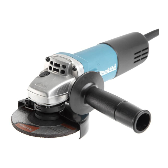
9556HN, 9557HN, 9558HN
Angle Grinders 100mm (4"), 115mm (4-1/2"), 125mm (5")
Current (A)
Cycle (Hz)
8.0
50/60
7.5
50/60
4.0
50/60
3.8
50/60
3.7
50/60
Model No.
Depressed center wheel
Wire cup brush
Abrasive disc
= rpm
-1
9557HN
Depressed center wheel 115-36 .... 1
Lock nut wrench 28 ...................... 1
Grip 36 complete .......................... 1
Model No.
Length (L)
Width (W)
Height (H)
Continuous Rating (W)
Input
840
840
840
840
840
9556HN
100 (4)
115 (4-1/2)
75 (3)
90 (3-1/2)
100 (4)
115 (4-1/2)
Double insulation
Australia, New Zealand: 2.0 (6.6), Other countries: 2.5 (8.2)
1.9 (4.2)
L
H
W
Dimensions: mm (")
9556HN
9557HN
271 (10-5/8)
118 (4-5/8)
129 (5-1/8)
97 (3-13/16)
Max. Output (W)
Output
500
500
500
500
500
9557HN
9558HN
125 (5)
90 (3-1/2)
125 (5)
11,000
2.0 (4.4)
2.1 (4.6)
9558HN
Depressed center wheel 125-36 .... 1
Lock nut wrench 35 ...................... 1
Grip 36 complete .......................... 1
PRODUCT
P 1/ 8
9558HN
139 (5-1/2)
106 (4-3/16)
1,000
1,000
1,000
1,000
1,000
Advertisement

Related Manuals for Makita 9556HN


Summary of Contents for Makita 9556HN
- Page 1 Note: The standard equipment for the tool shown above may vary by country. ptional accessories Wheel covers, Depressed center wheels, Abrasive discs, Rubber pads (for abrasive discs), Sanding lock nuts, Cut-off wheels, Super flanges (for 9557HN, 9558HN only), Wire cup brushes, Wire bevel brush (for 9556HN only), Dust collecting wheel guards...
-
Page 2: Necessary Repairing Tools
Retaining ring S and R pliers removing Retaining ring S-12 and Retaining ring R-32 [2] LUBRICATION Apply Makita grease N. No.1 to the following portions designated with the black triangle to protect parts and product from unusual abrasion. Item No. - Page 3 P 3/ 8 epair [3] DISASSEMBLY/ASSEMBLY [3] -1. Replacing Spiral Bevel Gear 10 DISASSEMBLING (1) Separate Rear cover from Motor housing by removing 4x18 Tapping screw, then disconnect Carbon brush from the commutator of Armature by moving the tail end of the spiral spring of Brush holder as drawn below. (Fig. 2) Note: No need to remove Carbon brushes in this step.
- Page 4 P 4/ 8 epair [3] DISASSEMBLY/ASSEMBLY [3] -1. Replacing Spiral Bevel Gear 10 (cont.) ASSEMBLING Fig. 6 Assemble by reversing the disassembly procedure. (Refer to Figs. 5, 4, 3 and 2) Name plate Note: Assemble Gear housing cover together with Armature Notch while facing its notch to the same side as Name plate.
- Page 5 P 5/ 8 epair [3] DISASSEMBLY/ASSEMBLY [3] -2. Replacing large Spiral Bevel Gear and Ball Bearing 6201DDW (cont.) ASSEMBLING Assemble by reversing the disassembly procedure. Note : • Do not forget to put Flat washer 12 in Bearing box. (Refer to Fig. 10.) •...
- Page 6 P 6/ 8 iring diagram [4] Connecting Lead wires [4]-1. Switch Connect Lead wires with Switch as drawn in Fig. D-2. Fig. D-2 [When Spacer is used] [When Spacer is not used] Power supply cord Switch button Switch Spacer [4] -2. Rear end of Field and Motor housing Route Field lead wires as drawn in Figs.
-
Page 7: Bottom View
P 7/ 8 iring diagram [4] Connecting Lead wires (cont.) [4]-3 Right and rear side of Motor housing Fig. D-4 Right side view Motor housing Motor housing Boss A Boss A Bottom view Route Lead wire of Power supply cord to Switch terminal No.2 so that it runs around boss A. -
Page 8: Wiring Diagram
P 8/ 8 iring diagram [4] Connecting lead wires (cont.) [4] -4. Field lead wires in the rear of Motor housing Fig. D-5 Connect Earth terminal on Lead wire (clear) of Noise suppressor* to this portion. Noise suppressor* Left side view Be sure that Field lead wires are tight in Motor housing.