Makita EA3200S Technical Information
Hide thumbs
Also See for EA3200S:
- Original instruction manual (244 pages) ,
- Operator's manual (140 pages) ,
- Instruction manual (100 pages)
Table of Contents
Advertisement
T
ECHNICAL INFORMATION
Model No.
Description
C
ONCEPT AND MAIN APPLICATIONS
Models EA3200S, EA3201S, EA3202S and EA3203S are entry class
petrol chain saws equipped with 32cc 2-stroke engine, featuring:
• Easy start, On-off choke combination switch and Primer pump
for providing higher maneuverability
• Compact and lightweight body for better handling
• Equipped with catalytic muffler to comply with all known exhaust
emission regulations (for EA3200S and EA3201S only)
These products are available in the following variations.
Model No.
EA3200S30A/ EA3202S30A
EA3200S35A/ EA3202S35A
EA3200S40B/ EA3202S40B
EA3201S30A/ EA3203S30A
EA3201S35A/ EA3203S35A
EA3201S40B/ EA3203S40B
The models also includes the accessories listed below in "Standard equipment".
S
pecification
Specifications
Type
Displacement: cm³ (cu.in.)
Engine
Fuel
Max. output: kW (PS)
Max. torque: N.m
Speed at no load
min.
:
In compliance with exhaust emission regulations;
EPA Phase 2, EU Stage 2
Fuel tank capacity: mL (US oz)
Chain oil tank capacity: L (US oz)
Carburetor
Ignition type
Easy start (Spring-assisted recoil starter)
Starting
system
Decompression valve
Primer pump
Clutch
Rotation limiter
Dry weight*: kg (lbs)
* without Guide bar, Saw chain
S
tandard equipment
Guide bar cover .............. 1
Socket wrench ................ 1
Screwdriver .................... 1
Note: The standard equipment for the tool shown above may vary by country.
EA3200S, EA3201S,
EA3202S, EA3203S
Petrol Chain Saws
Tool-less tension
Catalytic
adjustment of
muffler
saw chain
No
Yes/ No
No
Yes/ No
No
Yes/ No
Yes
Yes/ No
Yes
Yes/ No
Yes
Yes/ No
Model
= rpm
-1
Model
Length (L)
Width (W)
Height (H)
Guide bar
length: mm
cutter type
300
90SG-46E
350
90SG-52E
400
91VG-56E
300
90SG-46E
350
90SG-52E
400
91VG-56E
EA3200S/ EA3201S
EA3202S/ EA3203S
2-stroke
32 (2.0)
Mixed gasoline
(Mixture ratio of 50:1 [JASO FC or ISO EGD] )
1.35 (1.9) at 10,000 rpm
1.6 at 7,000 rpm
12,800
Yes
(Catalytic converter)
0.4 (13.5)
0.28 (9.5)
Diaphragm
Digital CDI
Yes
No
Yes
Yes
Yes
4.1/ 4.2 (9.0/ 9.3)
OFFICIAL USE
for ASC & Sales Shop
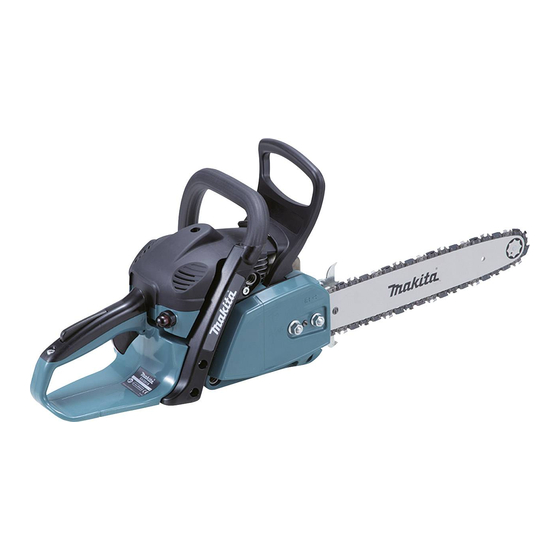
PRODUCT
W
H
L
(The image above is EA3201S.)
Dimensions: mm (")
EA3200S,
EA3201S,
EA3202S
EA3203S
405 (16)
250 (9-7/8)
269 (10-5/8)
273 (10-3/4)
Saw chain
gauge
3/8"
3/8"
3/8"
3/8"
3/8"
3/8"
No
4.0/ 4.1 (8.8/ 9.0)
O
ptional accessories
Saw chains
Guide bars (Sprocket nose type)
Chain oil
Engine oil
P 1/ 15
Advertisement
Table of Contents

Related Manuals for Makita EA3200S


Summary of Contents for Makita EA3200S
- Page 1 EA3202S, EA3203S Description Petrol Chain Saws ONCEPT AND MAIN APPLICATIONS Models EA3200S, EA3201S, EA3202S and EA3203S are entry class (The image above is EA3201S.) petrol chain saws equipped with 32cc 2-stroke engine, featuring: Dimensions: mm (") • Easy start, On-off choke combination switch and Primer pump...
- Page 2 3x10 Tapping screw Gear cover professional Tension slide 3x10 Tapping screw ASSEMBLING Assemble the components by reversing the disassembling procedure. Be sure to apply Makita grease N No. 2 on the engaged teeth of Helical gear 18 and Helical gear 11.
- Page 3 If there is damage/ wear on Clutch dram assembly, replace it to new one. (2) Apply a little amount of Makita grease N No. 2 to the needle bearing portion of Clutch drum assembly. (3) Set Clutch drum assembly, Flat washer 8 and Retaining ring E type 6 in place.
- Page 4 Assemble the components by reversing the disassembling procedure. Note: • Be sure to apply Makita grease N No. 2 on the engaged teeth of Helical gear 18 and Helical gear 11. • Make sure that Hand guard guide is not unhooked. Push it back into position that is 4mm distance from Pin B using Screwdriver so that Hand guard guide and Hand guard can be set in place.
- Page 5 P 5/ 15 epair [2] DISASSEMBLY/ ASSEMBLY [2]-4. Muffler section Note: • Wear gloves for safety. • Be careful that Muffler stays very hot for a while after running the engine. DISASSEMBLING (1) Remove Sprocket guard, Guide bar and Saw chain from machine. (2) Unscrew M5x40 Hexalobular socket head bolt and two M5x16 Hexalobular socket head bolts as drawn in Fig.
- Page 6 P 6/ 15 epair [2] DISASSEMBLY/ ASSEMBLY [2]-5. Clutch section DISASSEMBLING (1) Remove Sprocket guard, Guide bar and Saw chain from machine. (2) Pull Hand guard toward Tubular handle to release Chain brake. Then, remove “Clutch drum assembly”. Refer to [2]-2. (3) Set 1R396 on Clutch and turn it clockwise using Cordless impact driver with 19mm Socket bit.
- Page 7 P 7/ 15 epair [2] DISASSEMBLY/ ASSEMBLY [2]-6. Oil pump section Fig. 14 Refer to Figs. 14 and 15 for the mechanism of Oil pump section. Oil pump to supply Chain oil runs by Pump drive on Crank shaft. The gear teeth of Pump drive are engaged with those of Oil pump, Pump drive and therefore, Chain oil is supplied to Chain when Engine runs.
- Page 8 P 8/ 15 epair [2] DISASSEMBLY/ ASSEMBLY [2]-7. Recoil starter section Fig. 17 (The components of Starter complete) DISASSEMBLING Refer to Figs. 16 and 17 for the mechanism of Recoil starter section. Air guide plate (1) Remove three 5.5x16 Hexalobular tapping screws and Housing of Starter complete.
- Page 9 P 9/ 15 epair [2] DISASSEMBLY/ ASSEMBLY Fig. 20 [2]-9. Ignition coil Flag terminal DISASSEMBLING M5x20 of cable harness (1) Remove Sprocket guard, Guide bar and Saw chain from Hexalobular the machine. socket head (2) Remove “Recoil starter section”. See [2]-7. bolt (2 pcs.) Ignition coil (3) Remove Flag terminal on one of cable end from Ignition coil.
- Page 10 P 10/ 15 epair [2] DISASSEMBLY/ ASSEMBLY [2]-10. Air filter, Carburetor, Intermediate flange (cont.) To remove Intermediate flange: (1) Remove Choke lever from Engine housing complete (as drawn in Fig. 25), Tubular handle, and Spark plug. Remove Air filter cover, Air filter, and Intake manifold. (2) Remove 3x10 Tapping screw that fastens Contact spring and Cable harness to Intermediate flange.
- Page 11 P 11/ 15 epair [2] DISASSEMBLY/ ASSEMBLY [2]-10. Air filter, Carburetor, Intermediate flange (cont.) Fig. 28 Needle adjustment See Figs. 28 and 29 for the positions of Needle-idle (L) and Needle-high speed (H). Carburetor has two different specifications (Walbro-made and ZAMA-made). After tightening each Needle to the full, loosen them as listed below.
- Page 12 P 12/ 15 epair [2] DISASSEMBLY/ ASSEMBLY Fig. 32 [2]-11. Tank assembly Catch lever 5.5x16 Hexalobular Grip shell tapping screw DISASSEMBLY Unscrew 5.5x16 Hexalobular tapping screw and pull Grip shell half slightly up and toward the screw hole side. (Fig. 32) Note: When disassembling Throttle lever: Throttle lever (1) Remove Sprocket guard, then remove two Compression...
- Page 13 P 13/ 15 epair [2] DISASSEMBLY/ ASSEMBLY [2]-13. Fuel tank DISASSEMBLY (1) Referring to “DISASSEMBLY of [2]-11. Tank assembly”, disassemble the machine as drawn in Figs. 34 and 33. (2) Using long-nose pliers, carefully pull out the one end of Fuel line from Fuel nipple. (Refer to Figs 37 and 28) ASSEMBLY Note: Connect the one end of Fuel nipple to 1R127 (Refer to Fig.
- Page 14 P 14/ 15 epair [2] DISASSEMBLY/ ASSEMBLY [2]-15. Cylinder, Piston DISASSEMBLY (1) Remove “Air filter, Carburetor, and Intermediate flange” as mentioned in [2]-10. (Figs. 22, 23, 24, and 25) (2) Piston set can be separated from Crank shaft by removing Ring spring 8 from Piston with Long-nose pliers. (Fig. 38) ASSEMBLY Note: Supply 2-stroke engine oil to Piston and the inside of Cylinder in advance.
- Page 15 P 15/ 15 epair [3] TIGHTENING TORQUE...