Table of Contents
Troubleshooting

Related Manuals for Miller Bobcat 225D PLUS


Summary of Contents for Miller Bobcat 225D PLUS
- Page 1 OM-404 175 611T April 2002 Processes Stick (SMAW) Welding MIG (GMAW) Welding Flux Cored (FCAW) Welding Non-Critical TIG (GTAW) Welding Description Engine Driven Welding Generator Bobcat 225D Visit our website at www.MillerWelds.com...
- Page 2 We know you don’t have time to do it any other way. That’s why when Niels Miller first started building arc welders in 1929, he made sure his products offered long-lasting value and superior quality.
-
Page 3: Table Of Contents
TABLE OF CONTENTS SECTION 1 – SAFETY PRECAUTIONS - READ BEFORE USING ......1-1. Symbol Usage . -
Page 5: Section 1 - Safety Precautions - Read Before Using
SECTION 1 – SAFETY PRECAUTIONS - READ BEFORE USING rom _nd_11/98 1-1. Symbol Usage Means Warning! Watch Out! There are possible hazards with this procedure! The possible hazards are shown in the adjoining symbols. This group of symbols means Warning! Watch Out! possible Y Marks a special safety message. -
Page 6: Engine Hazards
WELDING can cause fire or explo- HOT PARTS can cause severe burns. sion. D Allow cooling period before maintaining. Welding on closed containers, such as tanks, D Wear protective gloves and clothing when drums, or pipes, can cause them to blow up. Sparks working on a hot engine. -
Page 7: Additional Symbols For Installation, Operation, And Maintenance
READ INSTRUCTIONS. stopping engine. D Do not let low voltage and frequency caused by D Use only genuine MILLER replacement parts. low engine speed damage electric motors. D Perform engine maintenance and service D Do not connect 50 or 60 Hertz motors to the 100 Hertz receptacle according to this manual and the engine where applicable. -
Page 8: Principal Safety Standards
H.F. RADIATION can cause interference. ARC WELDING can cause interference. D High-frequency (H.F.) can interfere with radio D Electromagnetic energy can interfere with navigation, safety services, computers, and sensitive electronic equipment such as communications equipment. computers and computer-driven equipment D Have only qualified persons familiar with such as robots. -
Page 9: Section 1 - Consignes De Sécurité - Lire Avant Utilisation
SECTION 1 – CONSIGNES DE SÉCURITÉ – LIRE AVANT UTILISATION rom _nd_fre 11/98 1-1. Signification des symboles Signifie Mise en garde ! Soyez vigilant ! Cette procédure présente des risques de danger ! Ceux-ci sont identifiés par des symboles adjacents aux directives. Ce groupe de symboles signifie Mise en garde ! Soyez vigilant ! Il y a des Y Identifie un message de sécurité... -
Page 10: Dangers Existant En Relation Avec Le Moteur
LE SOUDAGE peut provoquer un in- DES PIÈCES CHAUDES peuvent cendie ou une explosion. provoquer des brûlures graves. D Prévoir une période de refroidissement avant d’effec- Le soudage effectué sur des conteneurs fermés tels que tuer des travaux d’entretien. des réservoirs, tambours ou des conduites peut provoquer D Porter des gants et des vêtements de protection pour leur éclatement. -
Page 11: Dangers Supplémentaires En Relation Avec L'installation, Le Fonctionnement Et La Maintenance
DES ORGANES MOBILES peuvent L’ACIDE DE LA BATTERIE peut pro- provoquer des blessures. voquer des brûlures dans les YEUX et sur la PEAU. D Ne pas approcher les mains des ventilateurs, cour- roies et autres pièces en mouvement. D Ne pas renverser la batterie. D Maintenir fermés et fixement en place les portes, D Remplacer une batterie endommagée. -
Page 12: Principales Normes De Sécurité
LE RAYONNEMENT HAUTE FRÉ- LE SOUDAGE À L’ARC risque de QUENCE (H.F.) risque de provoquer provoquer des interférences. des interférences. D L’énergie électromagnétique risque de provoquer des interférences pour l’équipement électronique D Le rayonnement haute fréquence (H.F.) peut sensible tel que les ordinateurs et l’équipement com- provoquer des interférences avec les équipements mandé... -
Page 13: Section 2 - Definitions
SECTION 2 – DEFINITIONS 2-1. Symbol Definitions Fast Fast/Slow Stop Engine Slow (Idle) (Run, Weld/Power) (Run/Idle) Start Engine Glow Plug Temperature Fuel Check Injectors/ Check Valve Engine Oil Battery (Engine) Pump Clearance Read Operator’s Engine Amperes Volts Manual Gas Metal Arc Shielded Metal Arc Gas Tungsten Arc Circuit Breaker... -
Page 14: Dimensions, Weights, And Operating Angles
3-2. Dimensions, Weights, and Operating Angles Dimensions Height 31 in (787 mm) Width 18-3/4 in (476 mm) Y Do not exceed tilt angles or engine could Depth 46 in (1164 mm) be damaged or unit could tip. Y Do not move or operate unit where it could 18 in (457 mm) tip. -
Page 15: Duty Cycle
3-5. Duty Cycle Duty cycle is the percentage of 10 minutes that unit can weld at rated load without overheating. Y Exceeding duty cycle can damage unit void warranty. Continuous Welding 100% Duty Cycle at 225 Amperes CC/AC, 210 Amperes CC/DC, 200 Amperes CV/DC SB-119 454-A 3-6. -
Page 16: Section 4 - Installation
SECTION 4 – INSTALLATION 4-1. Installing Welding Generator Y Do not weld on base. Weld- ing on base can cause fuel tank fire or explosion. Bolt unit down using holes pro- Movement Airflow Clearance vided in base. Y Do not lift unit from end. 18 in Y Always securely... -
Page 17: Engine Prestart Checks
4-2. Engine Prestart Checks Check all fluids daily. Engine must be cold and on a level surface. Unit is shipped with 10W30 engine oil. Oil may be added at either oil fill. This unit has a low oil pressure shutdown switch. However, some conditions may cause engine damage before the en- gine shuts down. -
Page 18: Activating The Dry Charge Battery (If Applicable)
4-3. Activating The Dry Charge Battery (If Applicable) Remove battery from unit. Eye Protection – Safety Glasses Or Face Shield Rubber Gloves Vent Caps Sulfuric Acid Electrolyte (1.265 Specific Gravity) Well Fill each cell with electrolyte to bottom of well (maximum). Y Do not overfill battery cells. -
Page 19: Connecting The Battery
4-4. Connecting The Battery Y Connect negative (–) cable last. – Tools Needed: 3/8, 1/2 in Ref. 800 394-B / Ref. 192 785 / Ref. S-0756-D 4-5. Connecting To Weld Output Terminals Work Weld Output Terminal Electrode Weld Output Terminal Connect work cable to Work terminal. -
Page 20: Selecting Weld Cable Sizes
4-6. Selecting Weld Cable Sizes* Weld Cable Size** and Total Cable (Copper) Length in Weld Circuit Not Exceeding*** 150 ft 200 ft 250 ft 300 ft 350 ft 400 ft 100 ft (30 m) or Less (45 m) (60 m) (70 m) (90 m) (105 m) -
Page 21: Section 5 - Operating Welding Generator
SECTION 5 – OPERATING WELDING GENERATOR 5-1. Front Panel Controls Glow Plug Time Right Side ° ° F (21 ° ° 10 s F (0 ° ° 20 s –4 F (–20 Ref. 192 785 / Ref. 801 434 Engine Control Switch In Run/Idle position and Engine Control Coarse Adjust Switch switch in Run, engine runs at weld/power... -
Page 22: Section 6 - Operating Auxiliary Equipment
SECTION 6 – OPERATING AUXILIARY EQUIPMENT 6-1. Standard Receptacles Y If unit does not have GFCI re- ceptacles, GFCI- protected extension cord. Generator power decreases as weld current increases. Set Fine Adjust control R1 at 10 for full generator power. 120 V 20 A AC Duplex Receptacle RC3 120 V 20 A AC Duplex... -
Page 23: Csa Receptacle Option
6-2. CSA Receptacle Option Y If unit does not have GFCI re- ceptacles, GFCI- protected extension cord. 120/240 V 50 A AC Recep- tacle RC1 RC1 supplies 60 Hz single-phase power at weld/power speed. Maxi- mum output is 10 kVA/kW. 120 V 20 A AC Duplex Recep- tacle RC2 120 V 20 A AC Duplex Recep-... - Page 24 6-3. GFCI, South African, And Australian Generator Power Receptacle Options Y If unit does not have GFCI re- ceptacles, GFCI- protected extension cord. Generator power decreases as weld current increases. Set Fine Adjust control R1 at 10 for full generator power. Combined output of all receptacles limited to 8.5 kVA/kW rating of the generator.
-
Page 25: Wiring Optional 120/240 Volt Plug
6-4. Wiring Optional 120/240 Volt Plug The plug can be wired for a 240 V, 2-wire load or a 120/240V, 3-wire load. See circuit diagram. Plug Wired For 120/240 V, 3-Wire Load When wired for 120 V loads, each duplex receptacle shares a load Current Available In Amperes with one half of 240 V receptacle. -
Page 26: Section 7 - Maintenance And Troubleshooting
SECTION 7 – MAINTENANCE AND TROUBLESHOOTING 7-1. Maintenance Note Follow the storage procedure in the engine owner’s manual if the unit will not be used for an extended period. Y Stop engine before maintaining. See also Engine Manual and maintenance label. Recycle Maintain more often if used in severe conditions. - Page 27 500 h Service Welding Repair Or Replace Clean/Set Generator Brushes Cracked Cables Injectors.* And Slip Rings. And Cords. Service More Often In Dirty Conditions.* 1000 h Blow Out Or Vacuum Inside. Notes OM-404 Page 23...
-
Page 28: Maintenance Label
7-2. Maintenance Label OM-404 Page 24... -
Page 29: Inspecting And Cleaning Optional Spark Arrestor
7-3. Inspecting And Cleaning Optional Spark Arrestor Y Stop engine and let cool. Spark Arrestor Cleanout Plug Remove plug and remove dirt covering cleanout hole. Exhaust Pipe Start engine and run at idle speed to blow out cleanout hole. If nothing blows out of hole, briefly cover end of exhaust pipe with fireproof material. -
Page 30: Changing Engine Oil, Oil Filter, And Fuel Filter
7-4. Changing Engine Oil, Oil Filter, And Fuel Filter Y Stop engine and let cool. Oil Drain Valve 1/2 ID x 12 In Hose Oil Filter Oil Fill Cap Oil Dipstick Change engine oil and filter accord- ing to engine Owner’s Manual. Oil may be added at either oil fill. -
Page 31: Adjusting Engine Speed
7-5. Adjusting Engine Speed Engine speeds have been factory set and should not require adjust- ment. After tuning engine, check engine speeds with a tachometer. See table for proper no load engine speeds. necessary, adjust speeds as follows: Idle Speed Adjustment: 2000 rpm Throttle Cable Throttle Cable Stop Screw... - Page 32 B. Circuit Breaker CB8 Circuit Breaker CB8 CB8 protects the idle solenoid. If CB8 opens, engine drops to idle speed. Check throttle solenoid and cable for obstructions and throttle linkage for proper adjustment. Press button to reset circuit breaker. When a circuit breaker opens, it usually indicates a more seri- ous problem exists.
-
Page 33: Troubleshooting
7-7. Troubleshooting A. Welding Trouble Remedy No weld output. Check control settings (see Section 5-1). Check weld connections. Check fuse F1 and replace if open (see Section 7-6). Be sure all equipment is disconnected from receptacles when starting unit. Have Factory Authorized Service Agent check brushes, slip rings, and integrated rectifier SR2. Low weld output. - Page 34 C. Engine Trouble Remedy Engine will not crank. Check plug PLG4 connection and plug PLG8 connection. Check battery voltage. Check battery connections, and tighten if necessary. Have Factory Authorized Service Agent check continuity and connections of Engine Control switch S2, and replace if necessary.
-
Page 35: Section 8 - Electrical Diagram
SECTION 8 – ELECTRICAL DIAGRAM SC-182 630-B Figure 8-1. Circuit Diagram For Welding Generator OM-404 Page 31... -
Page 36: Section 9 - Generator Power Guidelines
SECTION 9 – GENERATOR POWER GUIDELINES 9-1. Selecting Equipment Generator Power Receptacles – Neutral Bonded To Frame 3-Prong Plug From Case Grounded Equipment 2-Prong Plug From Double Insulated Equipment Be sure equipment has this symbol and/or wording. aux_pwr 3/02 – Ref. ST-159 730 / ST-800 577 9-2. -
Page 37: Grounding When Supplying Building Systems
9-3. Grounding When Supplying Building Systems Equipment Grounding Terminal Grounding Cable GND/PE Use #10 AWG or larger insulated copper wire. Ground Device Y Ground generator to system earth ground if supplying power to a premises (home, shop, farm) wiring system. Use ground device as stated in electrical codes. - Page 38 9-5. Approximate Power Requirements For Industrial Motors Industrial Motors Rating Starting Watts Running Watts Split Phase 1/8 HP 1/6 HP 1225 1/4 HP 1600 1/3 HP 2100 1/2 HP 3175 Capacitor Start-Induction Run 1/3 HP 2020 1/2 HP 3075 3/4 HP 4500 1400 1 HP...
- Page 39 9-7. Approximate Power Requirements For Contractor Equipment Contractor Rating Starting Watts Running Watts Hand Drill 1/4 in 3/8 in 1/2 in Circular Saw 6-1/2 in 7-1/4 in 8-1/4 in 1400 1400 Table Saw 9 in 4500 1500 10 in 6300 1800 Band Saw 14 in...
- Page 40 9-8. Power Required To Start Motor Motor Start Code AC MOTOR Running Amperage VOLTS AMPS Motor HP CODE Motor Voltage PHASE To find starting amperage: Step 1: Find code and use table to find kVA/HP. If code is not listed, multiply running amperage by six to find starting amperage.
- Page 41 9-10. Typical Connections To Supply Standby Power Y Have only qualified persons perform these connections according to all applicable codes and safety practices. Power Company Service Meter Main and Branch Overcurrent Protection Customer-supplied equipment is required if Double-Pole, Double-Throw generator is to supply standby power during Transfer Switch emergencies or power outages.
- Page 42 9-11. Selecting Extension Cord (Use Shortest Cord Possible) Cord Lengths for 120 Volt Loads Y If unit does not have GFCI receptacles, use GFCI-protected extension cord. Maximum Allowable Cord Length in ft (m) for Conductor Size (AWG)* Current Load (Watts) (Amperes) 350 (106) 225 (68)
-
Page 43: Section 10 - Run-In Procedure
SECTION 10 – RUN-IN PROCEDURE run_in1 8/01 10-1. Wetstacking Y Do perform run-in procedure at less than 20 volts weld output and do not exceed duty cycle or equip- ment damage may occur. Welding Generator Run diesel engines near rated volt- age and current during run-in period to properly seat piston rings and prevent wetstacking. -
Page 44: Run-In Procedure Using Load Bank
10-2. Run-In Procedure Using Load Bank Y Stop engine. Y Do not touch hot exhaust pipe, engine parts, or load bank/grid. Y Keep exhaust and pipe away from flammables. Y Do perform run-in procedure at less than 20 volts weld output and do not exceed duty cycle or equip- ment damage may occur. -
Page 45: Run-In Procedure Using Resistance Grid
10-3. Run-In Procedure Using Resistance Grid Y Stop engine. Y Do not touch hot exhaust pipe, engine parts, or load bank/grid. Y Keep exhaust and pipe away from flammables. Y Do perform run-in procedure at less than 20 volts weld output and do not exceed duty cycle or equip- ment damage may occur. -
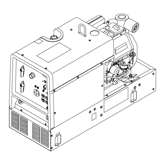
Page 46: Section 11 - Parts List
SECTION 11 – PARTS LIST ST-801 516-K Figure 11-1. Main Assembly OM-404 Page 42... - Page 47 Item Dia. Part Mkgs. Description Quantity Figure 11-1. Main Assembly ..... 192 041 . . . LABEL, use diesel fuel only .
- Page 48 Item Dia. Part Mkgs. Description Quantity Figure 11-1. Main Assembly (Continued) ..... 172 714 . . . BRACKET, engine mounting .
- Page 49 Item Dia. Part Mkgs. Description Quantity Figure 11-2. Panel, Front w/Components (Fig 11-1 Item 57) (Continued) ..... 119 014 . . . LEVER, switch .
- Page 50 Item Part Description Quantity Figure 11-3. Generator (Fig 11-1 Item 31) ..+205 901 HOUSING, generator front assy ......... .
- Page 51 Effective January 1, 2001 (Equipment with a serial number preface of “LB” or newer) This limited warranty supersedes all previous Miller warranties and is exclusive with no other Warranty Questions? guarantees or warranties expressed or implied. Call LIMITED WARRANTY – Subject to the terms and conditions APT, ZIPCUT &...
-
Page 52: Options And Accessories
Distributor Address City State For Service Call 1-800-4-A-Miller or see our website at www.MillerWelds.com to locate a DISTRIBUTOR or SERVICE AGENCY near you. Always provide Model Name and Serial/Style Number. Contact your Distributor for: Welding Supplies and Consumables Options and Accessories...
Need help?
Do you have a question about the Bobcat 225D PLUS and is the answer not in the manual?
Questions and answers