Table of Contents
Troubleshooting

Related Manuals for Miller Multimatic 220 AC/DC


Summary of Contents for Miller Multimatic 220 AC/DC
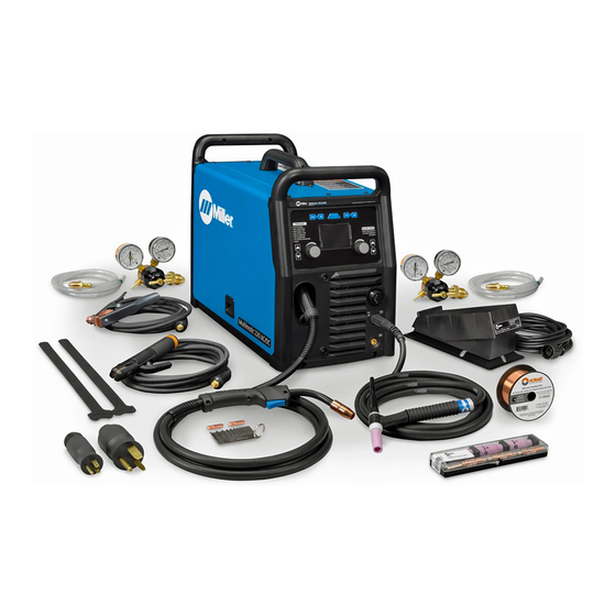
- Page 1 OM-281426C 2020−07 Processes Processes Multiprocess Welding Description Arc Welding Power Source Wire Feeder Multimatic 220 ® AC/DC For product information, File: Multiprocess Owner’s Manual translations, and more, visit www.MillerWelds.com...
- Page 2 We know you don’t have time to do it any other way. That’s why when Niels Miller first started building arc welders in 1929, he made sure his products offered long-lasting value and superior quality.
-
Page 3: Table Of Contents
TABLE OF CONTENTS SECTION 1 − SAFETY PRECAUTIONS - READ BEFORE USING ....... . . 1-1. - Page 4 TABLE OF CONTENTS 6-6. Welding Parameter Chart − 120V ............6-7.
-
Page 5: Section 1 − Safety Precautions - Read Before Using
SECTION 1 − SAFETY PRECAUTIONS - READ BEFORE USING som 2020−02 Protect yourself and others from injury — read, follow, and save these important safety precautions and operating instructions. 1-1. Symbol Usage DANGER! − Indicates a hazardous situation which, if Indicates special instructions. - Page 6 D Do not cut or weld on tire rims or wheels. Tires can explode if heat- FUMES AND GASES can be hazardous. ed. Repaired rims and wheels can fail. See OSHA 29 CFR 1910.177 listed in Safety Standards. D Do not weld on containers that have held combustibles, or on Welding produces fumes and gases.
-
Page 7: Additional Hazards For Installation, Operation, And Maintenance
D Never weld on a pressurized cylinder − explosion will result. CYLINDERS can explode if damaged. D Use only correct compressed gas cylinders, regulators, hoses, and fittings designed for the specific application; maintain them Compressed gas cylinders contain gas under high and associated parts in good condition. -
Page 8: California Proposition 65 Warnings
H.F. RADIATION can cause interference. ARC WELDING can cause interference. D High-frequency (H.F.) can interfere with radio D Electromagnetic energy can interfere with navigation, safety services, computers, and sensitive electronic equipment such as communications equipment. computers and computer-driven equipment such as robots. D Have only qualified persons familiar with electronic equipment D Be sure all equipment in the welding area is electromagnetically perform this installation. -
Page 9: Section 2 − Consignes De Sécurité − Lire Avant Utilisation
SECTION 2 − CONSIGNES DE SÉCURITÉ − LIRE AVANT UTILISATION som_2020−02_fre Pour écarter les risques de blessure pour vous−même et pour autrui — lire, appliquer et ranger en lieu sûr ces consignes relatives aux précautions de sécurité et au mode opératoire. 2-1. - Page 10 D Déplacer toutes les substances inflammables à une distance de LES PIÈCES CHAUDES peuvent 10,7 m de l’arc de soudage. En cas d’impossibilité les recouvrir provoquer des brûlures. soigneusement avec des protections homologués. D Ne pas toucher à mains nues les parties chaudes. D Ne pas souder dans un endroit là...
-
Page 11: Symboles De Dangers Supplémentaires En Relation Avec L'installation, Le Fonctionnement Et La Maintenance
D Protéger les bouteilles de gaz comprimé d’une chaleur excessive, Les CHAMPS ÉLECTROMAGNÉTIQUES (CEM) des chocs mécaniques, des dommages physiques, du laitier, des peuvent affecter les implants médicaux. flammes ouvertes, des étincelles et des arcs. D Placer les bouteilles debout en les fixant dans un support station- D Les porteurs de stimulateurs cardiaques et naire ou dans un porte-bouteilles pour les empêcher de tomber ou autres implants médicaux doivent rester à... -
Page 12: Proposition Californienne 65 Avertissements
D Effectuer régulièrement le contrôle et l’entretien de l’installation. LIRE LES INSTRUCTIONS. D Maintenir soigneusement fermés les portes et les panneaux des sources de haute fréquence, maintenir les éclateurs à une distan- D Lire et appliquer les instructions sur les ce correcte et utiliser une terre et un blindage pour réduire les étiquettes et le Mode d’emploi avant l’instal- interférences éventuelles. -
Page 13: Section 3 − Definitions
SECTION 3 − DEFINITIONS 3-1. Additional Safety Symbols And Definitions Warning! Watch Out! There are possible hazards as shown by the symbols. Safe1 2012−05 Drive rolls can injure fingers. Welding wire and drive parts are at welding voltage during operation − keep hands and metal objects away. -
Page 14: Miscellaneous Symbols And Definitions
3-2. Miscellaneous Symbols And Definitions Gas Tungsten Arc Amperage Remote Welding (GTAW) Torch Voltage Shielded Metal Circuit Breaker Arc Welding (SMAW) Rated No Load Positive Voltage (OCV) Shielded Metal Arc (SMAW) Direct Current Electrode Holder (DC) Negative Gas Metal Arc Alternating Welding (GMAW) Current (AC) -
Page 15: Section 4 − Specifications
4-3. Information About Default Weld Parameters And Settings NOTICE − Each welding application is unique. Although certain Miller Electric products are designed to determine and default to certain typical welding parameters and settings based upon specific and relatively limited application variables input by the end user, such default settings are for reference purposes only;... -
Page 16: Environmental Specifications
A complete Parts List is available at www.MillerWelds.com 4-7. Environmental Specifications A. IP Rating IP Rating IP21 This equipment is designed for indoor use and is not intended to be used or stored outside. IP21 2014−06 B. Temperature Specifications Operating Temperature Range* Storage/Transportation Temperature Range 14 to 104°F (−10 to 40°C) −4 to 131°F (−20 to 55°C) -
Page 17: Duty Cycle And Overheating For Mig (Gmaw)
A complete Parts List is available at www.MillerWelds.com 4-9. Duty Cycle And Overheating For MIG (GMAW) Duty Cycle is percentage of 10 minutes that unit can weld at rated load without overheating. If unit overheats, output stops. Wait fifteen minutes for unit to cool. Reduce amperage or duty cycle before starting to weld again. -
Page 18: Duty Cycle And Overheating For Tig (Gtaw)
A complete Parts List is available at www.MillerWelds.com 4-10. Duty Cycle And Overheating For TIG (GTAW) Duty Cycle is percentage of 10 minutes that unit can weld at rated load without overheating. If unit overheats, output stops. Wait fifteen minutes for unit to cool. Reduce amperage or duty cycle before starting to weld again. -
Page 19: Duty Cycle And Overheating For Stick (Smaw)
A complete Parts List is available at www.MillerWelds.com 4-11. Duty Cycle And Overheating For Stick (SMAW) Duty Cycle is percentage of 10 minutes that unit can weld at rated load without overheating. If unit overheats, output stops. Wait fifteen minutes for unit to cool. Reduce amperage or duty cycle before starting to weld again. -
Page 20: Section 5 − Installation
A complete Parts List is available at www.MillerWelds.com SECTION 5 − INSTALLATION 5-1. Selecting A Location Do not move or operate unit where it could tip. Movement Location And Airflow Special installation may be required where gasoline or volatile liquids are present − see NEC Article 511 or CEC Section 20. -
Page 21: Multi−Voltage Plug (Mvp) Connection
A complete Parts List is available at www.MillerWelds.com 5-2. Multi−Voltage Plug (MVP) Connection Selecting Plug Do not cut off power cord con- nector and rewire. The power cord connector and plugs will work with standard NEMA re- ceptacles. Modifying power cord, connector, and plugs will void product warranty. -
Page 22: Electrical Service Guide
A complete Parts List is available at www.MillerWelds.com 5-3. Electrical Service Guide Elec Serv 2017-01 Failure to follow these electrical service guide recommendations could create an electric shock or fire hazard. These recommenda- tions are for a dedicated circuit sized for the rated output and duty cycle of the welding power source. In dedicated circuit installations, the National Electrical Code (NEC) allows the receptacle or conductor rating to be less than the rating of the circuit protection device. -
Page 23: Connecting 120 Volt Input Power
A complete Parts List is available at www.MillerWelds.com 5-5. Connecting 120 Volt Input Power Installation must meet National and Local Codes − have only qualified persons make this installation. Special installation required where gasoline or volatile liquids are present − see NEC Article 511 or CEC Section 20. -
Page 24: Connecting 1-Phase Input Power For 240 Vac
A complete Parts List is available at www.MillerWelds.com 5-6. Connecting 1-Phase Input Power For 240 VAC =GND/PE Earth Ground 240 VAC, 1 Tools Needed: input4 2012-05 − 803 766-C / Ref. 802 443-A / 275173A OM-281426 Page 20... -
Page 25: Generator / Inverter Requirements
A complete Parts List is available at www.MillerWelds.com 5-6. Connecting 1-Phase Input Power For 240 VAC (Continued) primary voltage being applied, either 120 or Connect green or green/yellow grounding Installation must meet all National and 240 VAC. conductor to disconnect device grounding Local Codes −... -
Page 26: Stick Welding Connections
A complete Parts List is available at www.MillerWelds.com 5-8. Stick Welding Connections Turn off unit and disconnect input power before making connections. Do not use worn, damaged, undersized, or repaired cables. Weld Output Receptacle Work Clamp Receptacle Stick Electrode Holder And Cable Work Clamp And Cable Connect stick electrode holder... -
Page 27: Tig Welding Connections
A complete Parts List is available at www.MillerWelds.com 5-9. TIG Welding Connections Turn off unit and disconnect input power before making connections. Do not use worn, damaged, undersized, or repaired cables. Weld Output Receptacle Work Clamp Receptacle TIG Torch And Cable Work Clamp And Cable Connect TIG torch cable to the electrode receptacle and connect... -
Page 28: Mig Welding Connections
A complete Parts List is available at www.MillerWelds.com 5-10. MIG Welding Connections Ref. 275172A / Ref. 275167A / Ref. 275168A Connect work cable to work receptacle. Route trigger control cable through MIG Turn off unit and disconnect input Turn connector clockwise. gun hole. -
Page 29: Mig Gun Connection Inside Unit
A complete Parts List is available at www.MillerWelds.com 5-11. MIG Gun Connection Inside Unit Ref. 275167A Gun Securing Knob Loosen knob. Insert end of gun through Four Pin Trigger Control Cable Receptacle opening in front panel until gun end Gun Block bottoms against gun block. -
Page 30: Connecting Shielding Gas Supply
A complete Parts List is available at www.MillerWelds.com 5-12. Connecting Shielding Gas Supply Obtain gas cylinder and chain to running gear, wall, other stationary support so cylinder cannot fall and break off valve. Cylinder Valve Remove cap, stand to side of valve, and open valve slightly. -
Page 31: Installing Wire Spool And Adjusting Hub Tension
A complete Parts List is available at www.MillerWelds.com 5-13. Installing Wire Spool And Adjusting Hub Tension Wire Spool Retaining Nut − For 8 in. (203 mm) Spool Only Tools Needed: 1/2 in. Warning Installing 4 in. (102 mm) Wire Spool When a slight force is needed to turn spool, tension is set. -
Page 32: Threading Welding Wire
A complete Parts List is available at www.MillerWelds.com 5-14. Threading Welding Wire Wire Spool Welding Wire Inlet Wire Guide Pressure Adjustment Knob Drive Roll Outlet Wire Guide Gun Conduit Cable Lay gun cable out straight. Warning Tools Needed: Hold wire tightly to keep it from unraveling. -
Page 33: Removing Mig Gun To Replace With A Spool Gun
A complete Parts List is available at www.MillerWelds.com 5-15. Removing MIG Gun To Replace With A Spool Gun Tools Needed: Open Pressure Assembly. Cut Off End Of Wire. Turn Off Power. Knob Hold wire tightly to keep it from unraveling. Rewind Wire Onto Spool, Fasten Warning End Of Wire To Spool. -
Page 34: Section 6 − Operation
A complete Parts List is available at www.MillerWelds.com SECTION 6 − OPERATION 6-1. Controls Rear View Ref. 281252A / 282718A Process Select Buttons select the size of wire, rod, or tungsten for select material thickness for the selected the selected process. process. -
Page 35: Controls, Tig Aluminum Manual Mode
A complete Parts List is available at www.MillerWelds.com 6-2. Controls, TIG Aluminum Manual Mode Auto-Set Button Press button to turn Auto-Set fea- ture On or Off. Auto-Set is On when illuminated. Tungsten Size Buttons Press the Plus (+) or Minus (-) but- ton to adjust up or down. -
Page 36: Controls, Tig Steel/Stainless Manual Mode
A complete Parts List is available at www.MillerWelds.com 6-3. Controls, TIG Steel/Stainless Manual Mode Auto-Set Button Press button to turn Auto-Set fea- ture On or Off. Auto-Set is On when illuminated. Tungsten Size Buttons Press the Plus (+) or Minus (-) but- ton to adjust up or down. -
Page 37: Controls, Mig Manual Mode
A complete Parts List is available at www.MillerWelds.com 6-5. Controls, MIG Manual Mode Auto-Set Button Press button to turn Auto-Set fea- ture On or Off. Auto-Set is On when illuminated. Volts Adjustment Knob Wire Feed Speed Adjustment Knob Ref. 281252A Notes OM-281426 Page 33... -
Page 38: Welding Parameter Chart − 120V
A complete Parts List is available at www.MillerWelds.com 6-6. Welding Parameter Chart − 120V Ref. 282870-A OM-281426 Page 34... -
Page 39: Welding Parameter Chart − 240V
A complete Parts List is available at www.MillerWelds.com 6-7. Welding Parameter Chart − 240V Ref. 282870-A OM-281426 Page 35... -
Page 40: Entering Setup Menu
A complete Parts List is available at www.MillerWelds.com 6-8. Entering Setup Menu Ref. 281252A Wire/Rod/Tungsten Minus (−) Button press then release the Wire/Rod/Tungsten To move to the previous setup menu, press Minus (−) button and Material Thickness the Material Thickness Minus (−) button. Material Thickness Minus (−) Button Plus (+) button. -
Page 41: Internal Motor 24 Inch Calibration (Menu 1 Of 12)
A complete Parts List is available at www.MillerWelds.com 6-9. Internal Motor 24 Inch Calibration (Menu 1 Of 12) Ref. 281252A setup menu. and verify that a check mark appears next to The unit’s internal drive motor is calibrated 500 ipm. To perform a motor calibration 24 in. -
Page 42: Spoolmatet 24 Inch Calibration (Menu 3 Of 12)
A complete Parts List is available at www.MillerWelds.com 6-11. Spoolmatet 24 Inch Calibration (Menu 3 Of 12) Wire/Rod/Tungsten Minus (−) Button Material Thickness Plus (+) Button Material Thickness Minus (−) Button Left Adjustment Knob Right Adjustment Knob Spoolmate 100 and 150 drive motors are unique to this weld- ing power source. -
Page 43: Spoolmate Run-In Speed (Menu 4 Of 12)
A complete Parts List is available at www.MillerWelds.com 6-12. Spoolmate Run-In Speed (Menu 4 Of 12) Wire/Rod/Tungsten Minus (−) Button Auto-Set Button Material Thickness Plus (+) Button Follow instructions in Section 6-8 to enter the setup menu. To change the run−in setting, press the Auto−Set button. -
Page 44: Primary Logs (Menu 6 Of 12)
A complete Parts List is available at www.MillerWelds.com 6-14. Primary Logs (Menu 6 Of 12) Material Thickness Minus (−) Button Material Thickness Plus (+) Button Follow instructions in Section 6-8 to enter the setup menu. Primary Logs menu displays power cycles, 120 volt time, and 240 volt time. -
Page 45: Factory Reset (Menu 8 Of 12)
A complete Parts List is available at www.MillerWelds.com 6-16. Factory Reset (Menu 8 Of 12) Material Thickness Minus (−) Button Material Thickness Plus (+) Button Auto-Set Button A Factory Reset will reset the primary logs data, process logs data, error logs data, selected process, and all process set- tings. -
Page 46: Control Software (Menu 10 Of 12)
A complete Parts List is available at www.MillerWelds.com 6-18. Control Software (Menu 10 Of 12) Control Software information is for factory and service use only. Follow instructions in Section 6-8 to enter the setup menu. To exit menu, simultaneously press and release the Wire/Rod/Tung- sten Minus (−) button and Material Thickness Plus (+) button, or turn... -
Page 47: Tig Postflow Control (Menu 12 Of 12)
A complete Parts List is available at www.MillerWelds.com 6-20. TIG Postflow Control (Menu 12 Of 12) Wite/Rod/Tungsten Minus (−) Button Auto-Set Button Material Thickness Plus (+) Button Right Encoder Follow instructions in Section 6-8 to enter the setup menu. To adjust TIG postflow, turn right encoder. -
Page 48: Section 7 − Maintenance & Troubleshooting
A complete Parts List is available at www.MillerWelds.com SECTION 7 − MAINTENANCE & TROUBLESHOOTING 7-1. Routine Maintenance Maintain more often Disconnect power before maintaining. during severe conditions. n = Check Z = Change ~ = Clean l = Replace Reference * To be done by Factory Authorized Service Agent Every Months... -
Page 49: Changing Drive Roll Or Wire Inlet Guide
A complete Parts List is available at www.MillerWelds.com 7-3. Changing Drive Roll Or Wire Inlet Guide Inlet Wire Guide Remove guide by pressing on barbed area or cutting off one end near housing and pulling it out of hole. Push new guide into hole from rear until it snaps in place. -
Page 50: Error Messages
Wait for unit to cool down. If the fan is not running, welder cools down. maximum limit. contact Miller Electric Mfg. LLC service department. MIG gun or spool gun trigger is engaged on power Shorted trigger−Release 4−pin Release 4−pin trigger to clear error. - Page 51 The primary boost has not successfully been Cycle power to clear error. If this error persists after error. established. a power cycle, contact Miller Electric Mfg. LLC ser- vice department. Over voltage−Cycle power to Primary voltage is above 310 volts.
-
Page 52: Troubleshooting
A complete Parts List is available at www.MillerWelds.com 7-5. Troubleshooting Trouble Remedy No weld output; unit completely Place line disconnect switch in On position. inoperative. Check and replace line fuse(s), if necessary, or reset supplementary protector. Be sure power cord is plugged in and that receptacle is receiving input power. No weld output;... - Page 53 A complete Parts List is available at www.MillerWelds.com Notes OM-281426 Page 49...
-
Page 54: Section 8 − Electrical Diagram
SECTION 8 − ELECTRICAL DIAGRAM Figure 8-1. Circuit Diagram OM-281426 Page 50... - Page 55 281418-A OM-281426 Page 51...
-
Page 56: Section 9 − High Frequency
SECTION 9 − HIGH FREQUENCY 9-1. Welding Processes Requiring High Frequency High-Frequency Voltage TIG − helps arc jump air gap between torch and workpiece and/ or stabilize the arc. high_freq 2018-01 9-2. Installation Showing Possible Sources Of HF Interference Weld Zone 11, 12 50 ft (15 m) -
Page 57: Recommended Installation To Reduce Hf Interference
9-3. Recommended Installation To Reduce HF Interference Weld Zone 50 ft (15 m) 50 ft (15 m) Ground all metal ob- jects and all wiring in welding zone using #12 AWG wire. Ground workpiece if required by Nonmetal codes. Building Best Practices Followed Metal Building Ref. -
Page 58: Section 10 − Selecting A Tungsten For Dc Or Ac Welding With Inverter Machines
SECTION 10 − SELECTING AND PREPARING A TUNGSTEN FOR DC OR AC WELDING WITH INVERTER MACHINES gtaw_Inverter_2018-01 Whenever possible and practical, use DC weld output instead of AC weld output. 10-1. Selecting Tungsten Electrode ( Wear Clean Gloves To Prevent Contamination Of Tungsten A. -
Page 59: Preparing Tungsten Electrode For Dc Electrode Negative (Dcen) Welding
10-2. Preparing Tungsten Electrode For DC Electrode Negative (DCEN) Welding Or AC Welding With Inverter Machines Grinding the tungsten electrode produces dust and flying sparks which can cause injury and start fires. Use local exhaust (forced ventilation) at the grinder or wear an approved respirator. Read MSDS for safety information. -
Page 60: Section 11 − Guidelines For Tig Welding (Gtaw)
SECTION 11 − GUIDELINES FOR TIG WELDING (GTAW) Ref. gtaw_Phase_2018−01 11-1. Positioning The Torch Grinding the tungsten elec- trode produces dust and fly- ing sparks which can cause injury and start fires. Use lo- cal exhaust (forced ventila- tion) at the grinder or wear an approved respirator. -
Page 61: Torch Movement During Welding
11-2. Torch Movement During Welding Tungsten Without Filler Rod ° Welding direction Form pool Tilt torch Move torch to front of pool. Repeat process. Tungsten With Filler Rod ° ° Welding direction Form pool Tilt torch Add filler metal Remove rod Move torch to front of pool. -
Page 62: Section 12 − Gmaw Welding (Mig) Guidelines
SECTION 12 − GMAW WELDING (MIG) GUIDELINES 12-1. Typical GMAW (MIG) Process Connections Weld current can damage electronic parts in vehicles. Disconnect both battery cables before welding on a vehicle. Place work clamp as close to the weld as possible. Regulator/ Flowmeter Wire Feeder/... - Page 63 12-3. Holding And Positioning Welding Gun Welding wire is energized when gun trigger is pressed. Before lowering helmet and pressing trig- ger, be sure wire is no more than 1/2 in. (13 mm) past end of nozzle, and tip of wire is positioned cor- rectly on seam.
- Page 64 12-5. Gun Movement During Welding Normally, a single stringer bead is satisfactory for most narrow groove weld joints; however, for wide groove weld joints or bridging across gaps, a weave bead or multiple stringer beads works better. Stringer Bead − Steady Movement Along Seam Weave Bead −...
- Page 65 12-8. Troubleshooting − Excessive Spatter Excessive Spatter − scattering of molten metal particles that cool to solid form near weld bead. S-0636 Possible Causes Corrective Actions Wire feed speed too high. Select lower wire feed speed. Voltage too high. Select lower voltage range. Electrode extension (stickout) too long.
- Page 66 12-11. Troubleshooting − Lack Of Penetration Lack Of Penetration − shallow fusion between weld metal and base metal. Lack of Penetration Good Penetration S-0638 Possible Causes Corrective Actions Improper joint preparation. Material too thick. Joint preparation and design must provide access to bottom of groove while maintaining proper welding wire extension and arc characteristics.
- Page 67 12-14. Troubleshooting − Waviness Of Bead Waviness Of Bead − weld metal that is not parallel and does not cover joint formed by base metal. S-0641 Possible Causes Corrective Actions Welding wire extends too far out of nozzle. Be sure welding wire extends not more than 1/2 in. (13 mm) beyond nozzle. Unsteady hand.
- Page 68 12-16. Common GMAW (MIG) Shielding Gases This is a general chart for common gases and where they are used. Many different combinations (mixtures) of shielding gases have been developed over the years. The most commonly used shielding gases are listed in the following table. Application Short Short...
- Page 69 12-17. Troubleshooting Guide For Semiautomatic Welding Equipment Problem Probable Cause Remedy Too little pressure on wire feed rolls. Increase pressure setting on wire feed rolls. Wire feed motor operates, but wire does not feed. Incorrect wire feed rolls. Check size stamped on wire feed rolls, replace to match wire size and type if necessary.
-
Page 70: Section 13 − Guidelines For Stick Welding (Smaw)
SECTION 13 − GUIDELINES FOR STICK WELDING (SMAW) 13-1. Stick Welding Procedure Weld current starts when electrode touches work- piece. Weld current can damage electronic parts in vehicles. Disconnect both battery Equipment Needed: Tools Needed: cables before welding on a vehicle. -
Page 71: Electrode And Amperage Selection Chart
13-2. Electrode And Amperage Selection Chart 6010 DEEP 3/32 MIN. PREP, ROUGH HIGH SPATTER 6011 DEEP 6010 5/32 & 6013 EP,EN GENERAL 3/16 6011 7/32 SMOOTH, EASY, 7014 EP,EN FAST 1/16 LOW HYDROGEN, 7018 5/64 STRONG 3/32 SMOOTH, EASY, FLAT 7024 EP,EN 6013... -
Page 72: Positioning Electrode Holder
13-4. Positioning Electrode Holder End View Of Work Angle Side View Of Electrode Angle After learning to start and hold an arc, practice running beads of weld metal on flat plates using a full electrode. ° ° Hold the electrode nearly per- pendicular to the work, although tilting it ahead (in the direction of °... -
Page 73: Conditions That Affect Weld Bead Shape
13-7. Conditions That Affect Weld Bead Shape Weld bead shape is affected by electrode angle, arc length, travel speed, and thickness of base metal. Correct Angle Angle Too Large ° - ° Angle Too Small Electrode Angle Drag Spatter Arc Length Normal Too Long Too Short... -
Page 74: Welding Groove (Butt) Joints
13-10. Welding Groove (Butt) Joints Tack Welds Prevent butt joint distortion by tack welding the materials in position before final weld. Workpiece distortion occurs when heat is applied locally to a joint. One side of a metal plate will curl up toward the weld. -
Page 75: Weld Test
13-12. Weld Test Vise Weld Joint Hammer Strike the weld joint in the direction shown. A good weld bends over but does not break. If the weld breaks, examine it to determine the cause. If the weld is porous (many holes), the arc length was probably too long. - Page 76 Lack Of Penetration − shallow fusion between weld metal and base metal. Lack of Penetration Good Penetration Possible Causes Remedy Improper joint preparation. Material too thick. Joint preparation and design must provide access to bottom of groove. Improper weld technique. Keep arc on leading edge of weld puddle.
-
Page 77: Section 14 − Parts List
SECTION 14 − PARTS LIST 14-1. Recommended MIG Spare Parts Part Description Quantity ..261157 ....Roll, Drive .024, .030-.035V Wire, .035VK Wire . - Page 78 Notes...
- Page 79 Effective January 1, 2020 (Equipment with a serial number preface of NA or newer) This limited warranty supersedes all previous Miller warranties and is exclusive with no other guarantees or warranties expressed or implied. LIMITED WARRANTY − Subject to the terms and conditions Supplied Air Respirator (SAR) Boxes and Panels below, Miller Electric Mfg.
- Page 80 Contact the Delivering Carrier to: File a claim for loss or damage during shipment. For assistance in filing or settling claims, contact your distributor and/or equipment manufacturer’s Transportation Department. © ORIGINAL INSTRUCTIONS − PRINTED IN USA 2020 Miller Electric Mfg. LLC 2020−01...
Need help?
Do you have a question about the Multimatic 220 AC/DC and is the answer not in the manual?
Questions and answers