Table of Contents
Advertisement
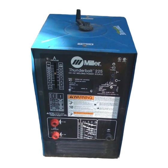
Rated
Amperage
Welding
Range
Output
Output
225 A @ 25
Low: 30 – 150A
Volts AC, 20%
Duty Cycle
High: 40 – 225A
*While idling
cover_om 4/95 – ST-052 359-D
OWNER'S
MANUAL
Thunderbolt 225
CC/AC Welding Power Source For SMAW (Stick) Welding
Amperes Input
Maximum
at Rated Load
Open-
Output 60 Hz,
Circuit
Single-Phase
Voltage
230 V
47.5
80 VAC
(8.6)*
1995 MILLER Electric Mfg. Co.
July 1995
Form: OM-116J
Effective With Serial No. KF943539
Overall Dimensions
KW
Height: 21-1/2 in (546 mm)
7.2
Width: 12-1/2 in (318 mm)
(0.22)*
Depth: 14 in (356 mm)
Weight
Net: 100 lb (45 kg)
Ship: 105 lb (48 kg)
PRINTED IN USA
Advertisement
Table of Contents
Troubleshooting

Related Manuals for Miller Thunderbolt 225


Summary of Contents for Miller Thunderbolt 225
- Page 1 80 VAC Width: 12-1/2 in (318 mm) (8.6)* (0.22)* Duty Cycle High: 40 – 225A Ship: 105 lb (48 kg) Depth: 14 in (356 mm) *While idling 1995 MILLER Electric Mfg. Co. cover_om 4/95 – ST-052 359-D PRINTED IN USA...
- Page 2 – every power source from This Owner’s Manual is designed to help you get the most out of your Miller is backed by the most Miller products. Please take time to read the Safety precautions. They will hassle-free warranty in the business.
-
Page 3: Section 1 - Safety Precautions For Arc Welding
SECTION 1 – SAFETY PRECAUTIONS FOR ARC WELDING safety_stickom1 6/95 1-1. Symbol Usage Y Marks a special safety message. Means Warning! Watch Out! There are possible hazards with this procedure! The possible hazards are shown in the adjoining symbols. Means NOTE; not safety related. This group of symbols means Warning! Watch Out! possible ELECTRIC SHOCK, MOVING PARTS, and HOT PARTS hazards. -
Page 4: Principal Safety Standards
1. Protect compressed gas cylinders from excessive heat, CYLINDERS can explode if damaged. mechanical shocks, slag, open flames, sparks, and arcs. Shielding gas cylinders contain gas under high 2. Keep cylinders away from any welding or other electrical circuits. pressure. If damaged, a cylinder can explode. Since gas cylinders are normally part of the welding 3. -
Page 5: Selecting Location And Installing Handle
SECTION 2 – INSTALLATION NOTE See User’s Guide on unit for process connection information. 2-1. Selecting A Location And Installing Handle Lifting Area Place hands where shown to move unit. Get help when moving unit. Running Gear Mounting Holes Rating Label Locate unit near correct input power. -
Page 6: Connecting Input Power
2-3. Connecting Input Power Y Have only qualified persons make this installation. GND/PE 230 VAC, GND/PE GND/PE Connect First Minimum input and grounding conductor size is 10 AWG/Kcmil, not to exceed 87 ft (26 m) in length. Install conductors in conduit or equivalent into a deenergized line disconnect device. -
Page 7: Section 3 - Operation
SECTION 3 – OPERATION 3-1. Controls Amperage Control Amperage Range Indicator Electrode (30–150 A) Weld Output Receptacle Electrode (40–225 A) Weld Output Receptacle When welding below 150 amps, use 30–150 A receptacle. Work Weld Output Receptacle Power Switch Ref. ST-155 574 / Ref. SC-107 516-F 3-2. -
Page 8: Routine Maintenance
SECTION 4 – MAINTENANCE & TROUBLESHOOTING 4-1. Routine Maintenance Y Disconnect power before maintaining. 3 Months Repair Or Replace Replace Unreadable Cracked Labels Cables Clean Tighten Weld Connections 6 Months 12 Months Blow Out Or Vacuum Lubricate Inside, Shunt During Heavy Service, Block Clean Monthly 4-2. -
Page 9: Troubleshooting
4-3. Troubleshooting Trouble Remedy No weld output; fan does not run. Be sure line disconnect switch is in On position (see Section 2-3). Check and replace line fuses if open. Reset breakers if necessary (see Section 2-3). Fan does not run; weld output okay. Be sure nothing is blocking movement of fan. -
Page 10: Main Assembly Parts
SECTION 6 – PARTS LIST Item Dia. Part Mkgs. Description Quantity Figure 6-1. Main Assembly ... . . 039 800 RECEPTACLE, jack plug red (consisting of) ...... -
Page 11: Transformer & Shunt Parts
Item Dia. Part Mkgs. Description Quantity Figure 6-2. Transformer & Shunt (Fig 6-1 Item 17) ....080 522 . . . BLOCK, anti-noise shunt .......... -
Page 12: Options And Accessories
OPTIONS AND ACCESSORIES No. 11A RUNNING GEAR (#041 637) A handle and two wheels with solid rubber tires mount easily to the frame of the Thunderbolt 225, providing convenient portability. 4/95... - Page 15 Effective January 1, 2000 (Equipment with a serial number preface of “LA” or newer) This limited warranty supersedes all previous Miller warranties and is exclusive with no other Warranty Questions? guarantees or warranties expressed or implied. Call LIMITED WARRANTY – Subject to the terms and conditions APT, ZIPCUT &...
-
Page 16: Owner's Record
Distributor Address City State For Service Call 1-800-4-A-Miller or see our website at www.MillerWelds.com to locate a DISTRIBUTOR or SERVICE AGENCY near you. Always provide Model Name and Serial/Style Number. Contact your Distributor for: Welding Supplies and Consumables Options and Accessories...
Need help?
Do you have a question about the Thunderbolt 225 and is the answer not in the manual?
Questions and answers