
Related Manuals for Miller Syncrowave 200


Summary of Contents for Miller Syncrowave 200
- Page 1 OM-225 389N 2009−06 Processes TIG (GTAW) Welding Stick (SMAW) Welding Description Arc Welding Power Source Syncrowave 200 File: TIG (GTAW) Visit our website at www.MillerWelds.com...
- Page 2 We know you don’t have time to do it any other way. That’s why when Niels Miller first started building arc welders in 1929, he made sure his products offered long-lasting value and superior quality.
-
Page 3: Table Of Contents
TABLE OF CONTENTS SECTION 1 − SAFETY PRECAUTIONS - READ BEFORE USING ........1-1. - Page 4 TABLE OF CONTENTS SECTION 8 − GUIDELINES FOR TIG WELDING (GTAW) ......... . 8-1.
-
Page 5: Section 1 − Safety Precautions - Read Before Using
SECTION 1 − SAFETY PRECAUTIONS - READ BEFORE USING som _2007−04 Protect yourself and others from injury — read and follow these precautions. 1-1. Symbol Usage DANGER! − Indicates a hazardous situation which, if Indicates special instructions. not avoided, will result in death or serious injury. The possible hazards are shown in the adjoining symbols or explained in the text. - Page 6 D Do not use welder to thaw frozen pipes. FUMES AND GASES can be hazardous. D Remove stick electrode from holder or cut off welding wire at contact tip when not in use. Welding produces fumes and gases. Breathing D Wear oil-free protective garments such as leather gloves, heavy these fumes and gases can be hazardous to your shirt, cuffless trousers, high shoes, and a cap.
-
Page 7: Additional Symbols For Installation, Operation, And Maintenance
1-3. Additional Symbols For Installation, Operation, And Maintenance FIRE OR EXPLOSION hazard. MOVING PARTS can cause injury. D Do not install or place unit on, over, or near D Keep away from moving parts such as fans. combustible surfaces. D Keep all doors, panels, covers, and guards D Do not install unit near flammables. -
Page 8: California Proposition 65 Warnings
1-4. California Proposition 65 Warnings For Gasoline Engines: Welding or cutting equipment produces fumes or gases which contain chemicals known to the State of California to Engine exhaust contains chemicals known to the State of cause birth defects and, in some cases, cancer. (California California to cause cancer, birth defects, or other reproduc- Health &... -
Page 9: Section 2 − Installation
SECTION 2 − INSTALLATION 2-1. Included with Your Unit 12 ft (3.7 m) Work Cable With Clamp And Quick-Connect WP1712SFDI 150 Amp TIG Torch with 12 ft (3.7 m) Cable And Quick-Connect Electrode Holder and Quick-Connect Gas Hose Gas Regulator Cable/T orch Hanger Foot Pedal Holder 8 ft (2.4 m) Primary Cord... -
Page 10: Dimensions And Weights
2-3. Dimensions And Weights Dimensions Height 29-3/4 in. (756 mm) Width 17-1/4 in. (438 mm) Length 23-1/2 in. (597 mm) 19-1/16 in. (484 mm) Front 1 in. (25 mm) 804 239-B 14-3/4 in. (375 mm) 1 in. (25 mm) 1/2 in. (13 mm) 4 Holes 7/16 in. -
Page 11: Duty Cycle Chart
2-6. Duty Cycle Chart Duty cycle is percentage of 10 minutes that unit can weld at rated load without overheating. NOTICE − Exceeding duty cycle can damage unit and void warranty. 40% Duty Cycle at 150 A AC/DC 4 Minutes Welding 6 Minutes Resting 226 798-A 2-7. -
Page 12: Ac Volt-Ampere Curves
2-8. AC Volt-Ampere Curves Volt-ampere curves show minimum and maximum voltage and amper- age output capabilities of welding AC TIG Min power source. Curves of other set- tings fall between curves shown. AC Stick Max AC Stick Min AC TIG Max AMPS ssb1.1 10/91 −... -
Page 13: Weld Output Terminals And Selecting Cable Sizes
2-9. Weld Output Terminals And Selecting Cable Sizes ARC WELDING can cause Electromagnetic Interference. To reduce possible interference, keep weld cables as short as possible, close together, and down low, such as on the floor. Locate welding operation 100 meters from any sensitive electronic equipment. Be sure this welding machine is installed and grounded according to this manual. -
Page 14: 115 Volts Ac Duplex Receptacle And Supplementary Protector Cb1
2-11. 115 Volts AC Duplex Receptacle And Supplementary Protector CB1 Turn Off power before con- necting to receptacle or re- setting protector. Supplementary Protector CB1 If CB1 opens, high frequency and output to the 115 volts ac duplex re- ceptacle stop. Press button to reset protector. -
Page 15: Typical Tig Connections
2-13. Typical TIG Connections Turn off power before mak- ing connections. Remote Foot Control A customer supplied remote finger- tip control may also be used. Torch Work Clamp Connect remote control, torch, and work clamp to receptacles as shown. Cylinder Chain or secure cylinder to running gear, wall, or other stationary support. -
Page 16: Typical Stick Connections
2-14. Typical Stick Connections Turn off power before mak- ing connections. Electrode Holder Work Clamp Connect electrode holder and work clamp to receptacles as shown. 2-15. Electrical Service Guide Failure to follow these electrical service guide recommendations could create an electric shock or fire hazard. These recommenda- tions are for a dedicated branch circuit sized for the rated output and duty cycle of the welding power source. -
Page 17: Connecting Input Power In 208-230 Volt Models
2-16. Connecting Input Power In 208-230 Volt Models Installation must meet all National and Local Codes − have only quali- fied persons make this installation. Disconnect and lockout/tagout in- put power before connecting input =GND/PE Earth Ground conductors from unit. Always connect green or green/ yellow conductor... - Page 18 B. Connecting Input Power In 460/575 Volt Models =GND/PE Earth Ground Tools Needed: 3/8 in 804 470-B Welding Power Source Input Power Con- Disconnect Device Input Power Connec- Installation must meet all National and nections tions Local Codes − have only qualified per- sons make this installation.
-
Page 19: Section 3 − Operation
SECTION 3 − OPERATION 3-1. Controls 0000 0000 228 528-A / 242 738-A Output Selector Switch (Polarity) Pulse Push Button Control See Section 3-2. Do not use AC output in damp areas, if See Section 3-5. Voltmeter And Parameter Adjust movement is confined, or if there is Main Amps Push Button See Section 3-2. -
Page 20: Ammeter, Voltmeter And Parameter Display
3-2. Ammeter, Voltmeter And Parameter Display Ammeter Displays actual amperage while welding. Meter also displays preset parameters for any of the following units of measure when they are ac- tive: amperage, time, percentage or frequency. Voltmeter Displays output or open-circuit volt- age while output is on. -
Page 21: Pulse Control
3-5. Pulse Control Ammeter Voltmeter Encoder Adjustment Control Pulse Control Pulsing is available only while using the TIG process, it cannot be se- 10.0 lected if the Stick process (see Sec- tion 3-4) is active. Controls can be adjusted while welding. Press Pulse push button to activate pulser function. -
Page 22: Balance/Dig Control
3-6. Balance/DIG Control Ammeter Voltmeter Encoder Adjustment Control Adjust Control Select desired process, AC TIG or DC Stick (see Section 3-4). Press Adjust push button to turn Balance/ DIG function and LED on. If AC TIG is selected, turn encoder control to select appropriate balance value (see Sec- tion 3-7). -
Page 23: Factory Parameter Defaults And Range And Resolution
3-7. Factory-Set Parameter Defaults And Range And Resolution Parameter Default Range And Resolution PROCESS TIG HF TIG HF, STICK A MAIN / PEAK 150 A 5 − 200 Amps 150 A 5 − 200 Amps PULSER ON / OFF 10 PPS 0.1−15 PPS PEAK t 20 −... -
Page 24: Postflow Control
3-8. Postflow Control Postflow time is automatically con- trolled. Auto-postflow provides a minimum of five seconds of post- flow for anything less than 50 amps of weld current, and an additional one second of postflow for each additional ten amps of weld current. Power Switch Process Control Encoder Adjust Control... -
Page 25: Selecting Syncro Start Characteristics
3-9. Selecting Syncro Start Characteristics Power Switch Main Amps Control Volt And Ammeters Process Selector Switch To change TIG HF Syncro starting char- acteristics, turn Off power, place Output Selector switch in desired position, DCEN, DCEP or AC. Each position has three start characteristics options. -
Page 26: Pulser Peak And Background
3-10. Pulser Peak And Background Power Switch Pulse Control Push and hold Pulser button and turn on power. Hold button for approxi- mately 7 seconds. Encoder Control Volt And Ammeter Press Pulse button to cycle parame- ters (see Section 3-7 for parameter ranges). -
Page 27: Timer/Cycle Counter
3-11. Timer/Cycle Counter 1234 Hour 0000 0000 MINS 1234 5678 Power Switch the Process and Pulse buttons, and turn and then the minutes are displayed for five power on. seconds. Process Control Cycle Display Timer Display The cycles are displayed for the next five Pulse Control seconds, and are read as 12,345,678 To read timer/cycle counter, press and hold... -
Page 28: Software Number/Revision
3-12. Software Number/Revision 0000 0000 REV.A Power Switch and hold the Process and Adjust buttons, seconds. and turn power on. Process Control Revision Display Software Number Display Adjust Control The revision is displayed for the next five To read software number/revision, press The software number is displayed for five seconds. -
Page 29: Section 4 − Maintenance And Troubleshooting
SECTION 4 − MAINTENANCE AND TROUBLESHOOTING 4-1. Routine Maintenance Disconnect power before maintaining. Maintain more often during severe conditions. 3 Months Replace o-ring in Electrode/Gas Replace unreadable labels. Output receptacle if cracked. Repair or replace cracked weld Repair or replace cracked gas cable. -
Page 30: Voltmeter/Ammeter Help Displays
4-3. Voltmeter/Ammeter Help Displays tory Authorized Service Agent. eration will continue when the unit has All directions are in reference to the cooled. front of the unit. All circuitry referred to OVER TEMP XFMR Help 9 Display is located inside the unit. Indicates the transformer of the unit has Indicates a short in the thermal protection Help 0 Display... -
Page 31: Troubleshooting
4-4. Troubleshooting The remedies listed below are recommendations only. If these remedies do not fix the trouble with your unit, have a Factory Authorized Service Agent check unit. There are no user serviceable parts inside unit. Refer to Section 4-3 for any Help (HLP) message displayed on voltmeter/ammeter. Trouble Remedy No weld output;... -
Page 32: Section 5 − Electrical Diagram
SECTION 5 − ELECTRICAL DIAGRAM 231 276-B Figure 5-1. Circuit Diagram For 208−230 Volt Models OM-225 389 Page 28... - Page 33 231 299-B Figure 5-2. Circuit Diagram For 460/575 Volt Models OM-225 389 Page 29...
-
Page 34: Section 6 − High Frequency
SECTION 6 − HIGH FREQUENCY 6-1. Welding Processes Requiring High Frequency High-Frequency Voltage TIG − helps arc jump air gap between torch and workpiece and/ or stabilize the arc. Work high_freq 7/05 − S-0693 6-2. Incorrect Installation Weld Zone 11, 12 50 ft (15 m) Sources of Direct High-Frequency... -
Page 35: Correct Installation
6-3. Correct Installation Weld Zone 50 ft (15 m) 50 ft (15 m) Ground all metal ob- jects and all wiring in welding zone using #12 AWG wire. Ground workpiece if required by codes. Nonmetal Building Metal Building Ref. S-0695 / Ref. S-0695 High-Frequency Source (welding Conduit Joint Bonding and Grounding Metal Building Requirements... -
Page 36: Section 7 − Selecting And Preparing A Tungsten For Dc Or Ac Welding
SECTION 7 − SELECTING AND PREPARING A TUNGSTEN FOR DC OR AC WELDING gtaw_Phase_2007−04 Whenever possible and practical, use DC weld output instead of AC weld output. 7-1. Selecting Tungsten Electrode ( Wear Clean gloves To Prevent Contamination Of Tungsten ♦... -
Page 37: Section 8 − Guidelines For Tig Welding (Gtaw)
SECTION 8 − GUIDELINES FOR TIG WELDING (GTAW) 2007−04 8-1. Positioning The Torch Grinding the tungsten elec- trode produces dust and fly- ing sparks which can cause injury and start fires. Use lo- cal exhaust (forced ventila- tion) at the grinder or wear an approved respirator. -
Page 38: Torch Movement During Welding
8-2. Torch Movement During Welding Tungsten Without Filler Rod ° Welding direction Form pool Tilt torch Move torch to front of pool. Repeat process. Tungsten With Filler Rod ° ° Welding direction Form pool Tilt torch Add filler metal Remove rod Move torch to front of pool. -
Page 39: Positioning Torch Tungsten For Various Weld Joints
8-3. Positioning Torch Tungsten For Various Weld Joints ° Butt Weld And Stringer Bead ° ° ° “T” Joint ° ° ° ° Lap Joint ° ° ° ° Corner Joint ° ° ST-162 003 / S-0792 OM-225 389 Page 35... -
Page 40: Stick Welding Procedure
SECTION 9 − STICK WELDING (SMAW) GUIDELINES 9-1. Stick Welding Procedure Weld current starts when electrode touches work- piece. Equipment Needed: Tools Needed: Weld current can damage electronic parts in vehicles. Disconnect both battery cables before welding on a vehicle. Place work clamp as close to the weld as possible. -
Page 41: Electrode And Amperage Selection Chart
9-2. Electrode and Amperage Selection Chart 6010 DEEP 3/32 MIN. PREP, ROUGH HIGH SPATTER 6011 DEEP 6010 5/32 & 6013 EP,EN GENERAL 3/16 6011 7/32 SMOOTH, EASY, 7014 EP,EN FAST 1/16 LOW HYDROGEN, 7018 5/64 STRONG 3/32 FLAT SMOOTH, EASY, 7024 EP,EN HORIZ... -
Page 42: Positioning Electrode Holder
9-4. Positioning Electrode Holder End View Of Work Angle Side View Of Electrode Angle ° ° ° ° Groove Welds ° ° ° ° Fillet Welds S-0060 9-5. Poor Weld Bead Characteristics Large Spatter Deposits Rough, Uneven Bead Slight Crater During Welding Bad Overlap Poor Penetration S-0053-A... -
Page 43: Conditions That Affect Weld Bead Shape
9-7. Conditions That Affect Weld Bead Shape Weld bead shape is affected electrode angle, length, travel speed, and thickness of base metal. Correct Angle ° - ° Angle Too Large Angle Too Small Electrode Angle Drag Spatter Arc Length Normal Too Long Too Short Travel Speed... -
Page 44: Butt Joints
9-9. Butt Joints Tack Welds Prevent edges of joint from draw- ing together ahead of electrode by tack welding the materials in posi- tion before final weld. Square Groove Weld Good for materials up to 3/16 in. (5 mm) thick. Single V-Groove Weld Good for materials 3/16 −... -
Page 45: Weld Test
9-12. Weld Test Vise Weld Joint Hammer Strike weld joint in direction shown. A good weld bends over but does not break. 2 To 3 in. (51-76 mm) 2 To 3 in. (51-76 mm) 1/4 in. (6.4 mm) S-0057-B 9-13. Troubleshooting Porosity −... - Page 46 Lack Of Penetration − shallow fusion between weld metal and base metal. Lack of Penetration Good Penetration Possible Causes Corrective Actions Improper joint preparation. Material too thick. Joint preparation and design must provide access to bottom of groove. Improper weld technique. Keep arc on leading edge of weld puddle.
- Page 47 Notes Work like a Pro! Pros weld and cut safely. Read the safety rules at the beginning of this manual. OM-225 389 Page 43...
-
Page 48: Section 10 − Parts List
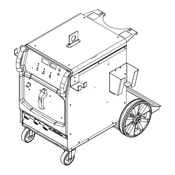
SECTION 10 − PARTS LIST Hardware is common and not available unless listed. 805 461-A Figure 10-1. Main Assembly OM-225 389 Page 44... - Page 49 ..199 479 LABEL, MILLER 9.562 X 4.000 HORIZONTAL ......
- Page 50 Item Dia. Part Mkgs. Description Quantity Figure 10-1. Main Assembly (continued) ..209 587 CAPACITOR ASSY ..........
- Page 51 Hardware is common and not available unless listed. 803 775-B Figure 10-2. Panel, Lower Dinse Connector Assembly Item Dia. Part Mkgs. Description Quantity 223 981 10-2. Panel, Lower Dinse Connector Assy (Figure 10-1 Item 56) ... . . 213 109 PANEL, LOWER DINSE CONN .
- Page 52 Hardware is common and not available unless listed. 804 399-A Figure 10-3. Rectifier Assembly Item Dia. Part Mkgs. Description Quantity 224 496 Figure 10-3. Rectifier Assembly (Figure 10-1 Item 40) ... . . 206 984 HEAT SINK,RECTIFIER .
- Page 53 Notes...
- Page 54 Notes...
- Page 55 Effective January 1, 2009 (Equipment with a serial number preface of LK or newer) This limited warranty supersedes all previous Miller warranties and is exclusive with no other Warranty Questions? guarantees or warranties expressed or implied. LIMITED WARRANTY − Subject to the terms and conditions...
-
Page 56: Options And Accessories
Contact the Delivering Carrier to: File a claim for loss or damage during shipment. For assistance in filing or settling claims, contact your distributor and/or equipment manufacturer’s Transportation Department. © ORIGINAL INSTRUCTIONS − PRINTED IN USA 2009 Miller Electric Mfg. Co. 2009−01...
Need help?
Do you have a question about the Syncrowave 200 and is the answer not in the manual?
Questions and answers