Table of Contents
Troubleshooting

Related Manuals for Miller Millermatic 255


Summary of Contents for Miller Millermatic 255
- Page 1 OM-279299C 2019−07 Processes Processes MIG (GMAW) Welding Pulsed MIG (GMAW-P) Description Arc Welding Power Source Wire Feeder Millermatic 255 For product information, File: MIG (GMAW) Owner’s Manual translations, and more, visit www.MillerWelds.com...
- Page 2 We know you don’t have time to do it any other way. That’s why when Niels Miller first started building arc welders in 1929, he made sure his products offered long-lasting value and superior quality.
-
Page 3: Table Of Contents
............5-4. Wiring Optional 240 Volt Plug (119172) For Connection To Miller Welder/Generator . - Page 4 TABLE OF CONTENTS SECTION 6 − OPERATION ..............6-1.
-
Page 5: Section 1 − Safety Precautions - Read Before Using
SECTION 1 − SAFETY PRECAUTIONS - READ BEFORE USING som 2018−01 Protect yourself and others from injury — read, follow, and save these important safety precautions and operating instructions. 1-1. Symbol Usage DANGER! − Indicates a hazardous situation which, if Indicates special instructions. - Page 6 D Do not cut or weld on tire rims or wheels. Tires can explode if heat- FUMES AND GASES can be hazardous. ed. Repaired rims and wheels can fail. See OSHA 29 CFR 1910.177 listed in Safety Standards. D Do not weld on containers that have held combustibles, or on Welding produces fumes and gases.
-
Page 7: Additional Symbols For Installation, Operation, And Maintenance
D Never weld on a pressurized cylinder − explosion will result. CYLINDERS can explode if damaged. D Use only correct compressed gas cylinders, regulators, hoses, and fittings designed for the specific application; maintain them Compressed gas cylinders contain gas under high and associated parts in good condition. -
Page 8: California Proposition 65 Warnings
H.F. RADIATION can cause interference. ARC WELDING can cause interference. D High-frequency (H.F.) can interfere with radio D Electromagnetic energy can interfere with navigation, safety services, computers, and sensitive electronic equipment such as communications equipment. computers and computer-driven equipment such as robots. D Have only qualified persons familiar with electronic equipment D Be sure all equipment in the welding area is electromagnetically perform this installation. -
Page 9: Section 2 − Consignes De Sécurité − Lire Avant Utilisation
SECTION 2 − CONSIGNES DE SÉCURITÉ − LIRE AVANT UTILISATION som_2018−01_fre Pour écarter les risques de blessure pour vous−même et pour autrui — lire, appliquer et ranger en lieu sûr ces consignes relatives aux précautions de sécurité et au mode opératoire. 2-1. - Page 10 D Déplacer toutes les substances inflammables à une distance de LES PIÈCES CHAUDES peuvent 10,7 m de l’arc de soudage. En cas d’impossibilité les recouvrir provoquer des brûlures. soigneusement avec des protections homologués. D Ne pas toucher à mains nues les parties chaudes. D Ne pas souder dans un endroit là...
-
Page 11: Dangers Supplémentaires En Relation Avec L'installation, Le Fonctionnement Et La Maintenance
D Protéger les bouteilles de gaz comprimé d’une chaleur excessive, Les CHAMPS ÉLECTROMAGNÉTIQUES (CEM) des chocs mécaniques, des dommages physiques, du laitier, des peuvent affecter les implants médicaux. flammes ouvertes, des étincelles et des arcs. D Placer les bouteilles debout en les fixant dans un support station- D Les porteurs de stimulateurs cardiaques et naire ou dans un porte-bouteilles pour les empêcher de tomber ou autres implants médicaux doivent rester à... -
Page 12: Proposition Californienne 65 Avertissements
D Effectuer régulièrement le contrôle et l’entretien de l’installation. LIRE LES INSTRUCTIONS. D Maintenir soigneusement fermés les portes et les panneaux des sources de haute fréquence, maintenir les éclateurs à une distan- D Lire et appliquer les instructions sur les ce correcte et utiliser une terre et un blindage pour réduire les étiquettes et le Mode d’emploi avant l’instal- interférences éventuelles. -
Page 13: Section 3 − Definitions
SECTION 3 − DEFINITIONS 3-1. Additional Safety Symbols And Definitions Warning! Watch Out! There are possible hazards as shown by the symbols. Safe1 2012−05 Drive rolls can injure fingers. Welding wire and drive parts are at welding voltage during operation − keep hands and metal objects away. -
Page 14: Miscellaneous Symbols And Definitions
3-2. Miscellaneous Symbols And Definitions Wire Feed Slow Amperage Locked Run-In Voltage Gas Metal Arc Remote Welding (GMAW) Rated No Load Voltage (OCV) Gas Metal Arc Circuit Breaker Welding (GMAW) Direct Current MIG / Gun Control (DC) Positive Self-Shielded Flux Alternating Cored Arc Current (AC) -
Page 15: Section 4 − Specifications
A complete Parts List is available at www.MillerWelds.com SECTION 4 − SPECIFICATIONS 4-1. Serial Number And Rating Label Location The serial number and rating information for this product is located on the back of unit. Use rating label to determine input power requirements and/or rated output. -
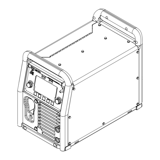
Page 16: Dimensions And Weight
A complete Parts List is available at www.MillerWelds.com 4-5. Dimensions And Weight Weight 84 lb (38.1 kg) 13.75 in. (349 mm) 19.25 in. (489 mm) 26.25 in. (667 mm) 907734 Notes Work like a Pro! Pros weld and cut safely. Read the safety rules at the beginning of this manual. -
Page 17: Duty Cycle And Overheating
A complete Parts List is available at www.MillerWelds.com 4-6. Duty Cycle And Overheating Duty Cycle is percentage of 10 minutes that unit can weld at rated load without overheating. If unit overheats, output stops. Wait 10 minutes for unit to cool. Reduce amperage or duty cycle before starting to weld again. -
Page 18: Section 5 − Installation
A complete Parts List is available at www.MillerWelds.com SECTION 5 − INSTALLATION 5-1. Selecting A Location Do not move or operate unit where it could tip. Movement Do not lift unit by strap threaded through both handles. Do not lift unit with cart attached. Location And Airflow Special installation may be required where gasoline or... -
Page 19: Electrical Service Guide
A complete Parts List is available at www.MillerWelds.com 5-2. Electrical Service Guide Elec Serv 2017−01 Failure to follow these electrical service guide recommendations could create an electric shock or fire hazard. These recommenda- tions are for a dedicated circuit sized for the rated output and duty cycle of the welding power source. In dedicated circuit installations, the National Electrical Code (NEC) allows the receptacle or conductor rating to be less than the rating of the circuit protection device. -
Page 20: Connecting 1-Phase Input Power
A complete Parts List is available at www.MillerWelds.com 5-3. Connecting 1-Phase Input Power =GND/PE Earth Ground 240 VAC, 1 Tools Needed: Ref. Input13 2015−08 OM-279299 Page 16... - Page 21 A complete Parts List is available at www.MillerWelds.com 5-3. Connecting 1-Phase Input Power (Continued) Receptacle Connect green or green/yellow grounding Installation must meet all National and (NEMA Type 6-50R) Customer conductor to disconnect device grounding Local Codes − have only qualified per- Supplied terminal first.
-
Page 22: Wiring Optional 240 Volt Plug (119172) For Connection To Miller Welder/Generator
A complete Parts List is available at www.MillerWelds.com 5-4. Wiring Optional 240 Volt Plug (119172) For Connection To Miller Welder/Generator With Split-Phase 240 Volt Auxiliary Power Input And Grounding Conductors Plug Wired for 240 V, 2-Wire 3 (Not Used) Load... -
Page 23: Generator Or Inverter Requirements
A complete Parts List is available at www.MillerWelds.com 5-5. Generator Or Inverter Requirements For maximum output Miller recom- mends 12kW or greater generator. Generator settings, if applicable. generator Voltage/Amperage Engine Control Switch must be set at “RUN” Control to 10 (or max) for maximum position −... -
Page 24: Selecting Cable Sizes
A complete Parts List is available at www.MillerWelds.com 5-6. Selecting Cable Sizes* NOTICE − The Total Cable Length in Weld Circuit (see table below) is the combined length of both weld cables. For example, if the power source is 100 ft (30 m) from the workpiece, the total cable length in the weld circuit is 200 ft (2 cables x 100 ft). Use the 200 ft (60 m) column to determine cable size. -
Page 25: Mig Welding Connections
A complete Parts List is available at www.MillerWelds.com 5-8. MIG Welding Connections FCAW-S − DCEN MIG/FCAW-G − DCEP (Direct Current Electrode Negative) (Direct Current Electrode Positive) 280401B / Ref. 275167A / 282987A Gun End Connect plug on end of cable to four pin Turn off unit and disconnect input receptacle inside unit. -
Page 26: Mig Gun Connection Inside Unit
A complete Parts List is available at www.MillerWelds.com 5-10. MIG Gun Connection Inside Unit Gun Securing Knob Gun Block Gun Outlet Wire Guide Gun End Loosen knob. Insert end of gun through opening in front panel until gun end bottoms against gun block. Tighten knob. -
Page 27: Connecting Shielding Gas Supply
A complete Parts List is available at www.MillerWelds.com 5-11. Connecting Shielding Gas Supply Obtain gas cylinder and chain to running gear, wall, other stationary support so cylinder cannot fall and break off valve. Cylinder Valve Remove cap, stand to side of valve, and open valve slightly. -
Page 28: Installing Wire Spool And Adjusting Hub Tension
A complete Parts List is available at www.MillerWelds.com 5-12. Installing Wire Spool And Adjusting Hub Tension Hand tighten knob clockwise. When a slight force is needed to turn spool, tension is set. To install either a 1 lb or 2 lb wire Installing 1 Or 2 lb Wire Spool spool, follow the procedure as shown in the illustration. -
Page 29: Threading Welding Wire For Mig Gun
A complete Parts List is available at www.MillerWelds.com 5-13. Threading Welding Wire For MIG Gun Wire Spool Welding Wire Inlet Wire Guide Pressure Adjustment Knob Drive Roll Outlet Wire Guide Gun Conduit Cable Lay gun cable out straight. Tools Needed: Hold wire tightly to keep it from unraveling. -
Page 30: Connecting Spoolmatic) 15A Or 30A Or Spoolmate 200 Gun
A complete Parts List is available at www.MillerWelds.com 5-14. Connecting Spoolmatic) 15A Or 30A Or Spoolmate 200 Gun Gun Trigger Plug Insert plug into receptacle, and tighten threaded collar. Weld Cable Shielding Gas Hose Route weld cable and gas hose through opening in panel. -
Page 31: Threading Welding Wire For Xr-Aluma-Pro Or Xr-Aluma-Pro Lite
A complete Parts List is available at www.MillerWelds.com 5-16. Threading Welding Wire For XR-Aluma-Pro Or XR-Aluma-Pro Lite Wire Spool Welding Wire Inlet Wire Guide Drive Roll Outlet Wire Guide Pressure Adjustment Knob Gun Conduit Cable Lay gun cable out straight. Tools Needed: Hold wire tightly to keep it from unraveling. -
Page 32: Threading Welding Wire Through Xr Guns
A complete Parts List is available at www.MillerWelds.com 5-17. Threading Welding Wire Through XR Guns Welding wire is electrically live when gun trigger is used to jog wire. For XR-Aluma-Pro Gun: Refer to Section 5-16 for instructions on feeding wire through welding pow- er source. -
Page 33: Threading Welding Wire For Spoolmatic 15/30A
A complete Parts List is available at www.MillerWelds.com 5-19. Threading Welding Wire For Spoolmatic 15/30A Top Cover Canister Canister Cover Thumbscrew (Canister Cover) Loosen thumbscrew and remove cover. Tools Needed: Wire Spool Loosen wire from spool, cut off bent wire, and pull 6 in. -
Page 34: Calibrating Spoolgun
A complete Parts List is available at www.MillerWelds.com 5-20. Calibrating Spoolgun 297061-D nozzle. Pull spoolgun trigger again to verify the ad- Spoolmatic 15/30A and Spoolmate justment. Repeat these steps until satisfied 200 motors are unique to this welding Follow instructions in Section 6-5 to enter with accuracy. -
Page 35: Section 6 − Operation
A complete Parts List is available at www.MillerWelds.com SECTION 6 − OPERATION 6-1. Controls 297061-D Auto-Set Button Use left knob to adjust voltage in MIG The USB port can also be used to mode, arc length in Pulsed MIG mode, or Press to turn Auto-Set On or Off. -
Page 36: Special Features
A complete Parts List is available at www.MillerWelds.com 6-2. Special Features A. MIG Mode In MIG mode, the left knob is used to adjust welding voltage within a range of 12 to 32 volts. The right knob is used to adjust wire feed speed within a range of 50 to 800 IPM. -
Page 37: Using Auto-Sett Elite
A complete Parts List is available at www.MillerWelds.com 6-3. Using Auto-Sett Elite 297061-D Auto-Set Button Material Thickness Left Button When using a spoolgun or push-pull Press to turn Auto-Set On or Off. gun in Auto-Set, the potentiometer on Material Thickness Right Button the gun is deactivated. -
Page 38: Using Manual Mode
A complete Parts List is available at www.MillerWelds.com 6-4. Using Manual Mode 297061-D Auto-Set Button Press Program to save favorite weld pro- Left Knob grams, up to four programs per weld Press Auto-Set to turn Auto-Set Off. Use left knob to adjust voltage in MIG mode process. -
Page 39: Manual Mig Setup Mode
A complete Parts List is available at www.MillerWelds.com 6-5. Manual MIG Setup Mode 297061-D Setup Button produces a stiffer arc. Inductance settings leased. This feature is used to fill the void or range from 0 to 99. The default setting is 50. crater at the end of the weld. -
Page 40: Setting Crater Time
A complete Parts List is available at www.MillerWelds.com 6-6. Setting Crater Time 297061-D Left Knob In the Setup menu, rotate the left knob to Crater Wire Feed Speed: Wire feed highlight Crater, and rotate the right knob speed range is 50 to 800 ipm. Right Knob to select Manual. -
Page 41: Manual Program Mode
A complete Parts List is available at www.MillerWelds.com 6-7. Manual Program Mode 297061-D Program Button Determine where you would like to save the Weld parameters may be changed while settings. Push and hold that Program soft using the program with the left and right Program Soft Keys key for two seconds. -
Page 42: Using Optional Mdx-250 Ez-Selectt Gun In Program Mode
A complete Parts List is available at www.MillerWelds.com 6-8. Using Optional MDX-250 EZ-Selectt Gun In Program Mode Ref. 800797-A Trigger Switch When this feature is enabled, the 4 LEDs on Tap the trigger twice. LEDs 1 and 2 on the the MDX−250 gun handle indicate which gun illuminate. -
Page 43: Pulsed Mig Auto-Sett Mode
A complete Parts List is available at www.MillerWelds.com 6-9. Pulsed MIG Auto-Sett Mode 297061-D Pulsed MIG is a spray transfer that pro- Wire Diameter Arc Length duces less heat input than conventional Arc length can be adjusted from 0-99. All Use soft key to select wire diameter. -
Page 44: Pulsed Mig Manual Mode
A complete Parts List is available at www.MillerWelds.com 6-10. Pulsed MIG Manual Mode 2, 5 297061-D Pulse Button to Pulse MIG welding chart for proper Wire Arc Length can be adjusted to help custom- Speed setting for metal and metal thick- ize your arc to the gas being used. -
Page 45: System
Back factory authorized service agents. push-pull gun being used. The selected Press soft key to return to Setup screen. License: Press soft key to display Miller Li- gun, AlumaPro or AlumaPro Lite, appears Counters censing Agreement. above the blue tab. -
Page 46: Support
A complete Parts List is available at www.MillerWelds.com 6-12. Support The Support screen allows the oper- ator to quickly access the Miller web- site and phone number to obtain more product information or get ser- vice support. Access the Support screen from the manual MIG home screen by press- ing Setup, then Support. -
Page 47: Section 7 − Weld Parameter Charts
A complete Parts List is available at www.MillerWelds.com SECTION 7 − WELD PARAMETER CHARTS 7-1. MIG And Flux Core Parameters 282495-D OM-279299 Page 43... -
Page 48: Section 8 − Maintenance &Troubleshooting
A complete Parts List is available at www.MillerWelds.com SECTION 8 − MAINTENANCE &TROUBLESHOOTING 8-1. Routine Maintenance Disconnect power before maintaining. Maintain more often during severe conditions. n = Check Z = Change ~ = Clean l = Replace * To be done by Factory Authorized Service Agent Every Months l Damaged Or Unreadable... -
Page 49: Aligning Drive Rolls And Wire Guide
Internal temperature of welder has exceeded the Wait for unit to cool down. If the fan is not run- Please wait while the welder cools maximum limit. ning, contact authorized Miller service center. down S Inverter Module S Output Rectifier S Secondary Magnetics MIG gun trigger is engaged on power up. - Page 50 The weld voltage is less than 10 volts for more than 0.2 seconds while welding. Output rectifier is damaged. Contact authorized Miller service center. Control board is damaged. Too much pressure on pressure adjust knob. Reduce pressure on the pressure adjust knob.
- Page 51 The two microcontrollers on the control board are Cycle power to clear error. If this error persists Inverter communications down no longer communicating. after a power cycle, contact authorized Miller ser- vice center. Network Error Primary communications down The wiring harness between the control board Contact authorized Miller service center.
-
Page 52: Troubleshooting
A complete Parts List is available at www.MillerWelds.com 8-6. Troubleshooting Trouble Remedy No weld output; unit completely Place line disconnect switch in On position. inoperative. Check and replace line fuse(s), if necessary, or reset supplementary protector. Be sure power cord is plugged in and that receptacle is receiving input power. No weld output;... -
Page 53: Section 9 − Parts List
A complete Parts List is available at www.MillerWelds.com SECTION 9 − PARTS LIST 9-1. MDX-250 MIG Gun Consumables And Recommended Spare Parts See OM-282976 (shipped with this product) for information on replacement consumables for the MDX welding gun. 9-2. Drive Roll And Wire Guide Kits Base selection of drive rolls upon the following recommended usages: V-Grooved rolls for hard wire. -
Page 54: Section 10 − Electrical Diagram
SECTION 10 − ELECTRICAL DIAGRAM Figure 10-1. Circuit Diagram OM-279299 Page 50... - Page 55 279043-C OM-279299 Page 51...
-
Page 56: Section 11 − Gmaw Welding (Mig) Guidelines
SECTION 11 − GMAW WELDING (MIG) GUIDELINES 11-1. Typical GMAW (MIG) Process Connections Weld current can damage electronic parts in vehicles. Disconnect both battery cables before welding on a vehicle. Place work clamp as close to the weld as possible. Regulator/ Flowmeter Wire Feeder/... - Page 57 11-3. Holding And Positioning Welding Gun Welding wire is energized when gun trigger is pressed. Before lowering helmet and pressing trig- ger, be sure wire is no more than 1/2 in. (13 mm) past end of nozzle, and tip of wire is positioned cor- rectly on seam.
- Page 58 11-5. Gun Movement During Welding Normally, a single stringer bead is satisfactory for most narrow groove weld joints; however, for wide groove weld joints or bridging across gaps, a weave bead or multiple stringer beads works better. Stringer Bead − Steady Movement Along Seam Weave Bead −...
- Page 59 11-8. Troubleshooting − Excessive Spatter Excessive Spatter − scattering of molten metal particles that cool to solid form near weld bead. S-0636 Possible Causes Corrective Actions Wire feed speed too high. Select lower wire feed speed. Voltage too high. Select lower voltage range. Electrode extension (stickout) too long.
- Page 60 11-11. Troubleshooting − Lack Of Penetration Lack Of Penetration − shallow fusion between weld metal and base metal. Lack of Penetration Good Penetration S-0638 Possible Causes Corrective Actions Improper joint preparation. Material too thick. Joint preparation and design must provide access to bottom of groove while maintaining proper welding wire extension and arc characteristics.
- Page 61 11-14. Troubleshooting − Waviness Of Bead Waviness Of Bead − weld metal that is not parallel and does not cover joint formed by base metal. S-0641 Possible Causes Corrective Actions Welding wire extends too far out of nozzle. Be sure welding wire extends not more than 1/2 in. (13 mm) beyond nozzle. Unsteady hand.
- Page 62 11-16. Common GMAW (MIG) Shielding Gases This is a general chart for common gases and where they are used. Many different combinations (mixtures) of shielding gases have been developed over the years. The most commonly used shielding gases are listed in the following table. Application Short Short...
- Page 63 11-17. Troubleshooting Guide For Semiautomatic Welding Equipment Problem Probable Cause Remedy Too little pressure on wire feed rolls. Increase pressure setting on wire feed rolls. Wire feed motor operates, but wire does not feed. Incorrect wire feed rolls. Check size stamped on wire feed rolls, replace to match wire size and type if necessary.
- Page 64 Notes...
- Page 65 Notes...
- Page 66 Notes...
- Page 67 Effective January 1, 2019 (Equipment with a serial number preface of MK or newer) This limited warranty supersedes all previous Miller warranties and is exclusive with no other guarantees or warranties expressed or implied. LIMITED WARRANTY − Subject to the terms and conditions Subarc Wire Drive Assemblies below, Miller Electric Mfg.
- Page 68 Contact the Delivering Carrier to: File a claim for loss or damage during shipment. For assistance in filing or settling claims, contact your distributor and/or equipment manufacturer’s Transportation Department. © ORIGINAL INSTRUCTIONS − PRINTED IN USA 2019 Miller Electric Mfg. LLC 2019−01...
Need help?
Do you have a question about the Millermatic 255 and is the answer not in the manual?
Questions and answers
My Millermatic 255 will start the gas flow then 2 - 3 sec later stop the gas flow