ABB ACH550 Installation Manual
Bacnet/ip router module rbip-01
Hide thumbs
Also See for ACH550:
- User manual (109 pages) ,
- Installation, operation and maintenance manual (18 pages) ,
- Quick start manual (6 pages)
Table of Contents
Advertisement
Quick Links
Download this manual
See also:
User Manual
Advertisement
Table of Contents

Related Manuals for ABB ACH550


Summary of Contents for ABB ACH550
- Page 1 ACH550 Installation Manual BACnet/IP Router Module RBIP-01...
- Page 2 RBIP-01 Router and ACH550 Drive manuals RBIP-01 BACnet/IP ROUTER PROTOCOL MANUALS MANUALS RBIP-01 BACnet/IP Router Module BACnet® Protocol Installation Manual ACH550 AC Drives 3AUA0000040168 (English) 3AUA0000004591 (English) RBIP-01 BACnet/IP Router Module Embedded Fieldbus (EFB) Control User’s Manual 3AFE68320658 (English) 3AUA0000040159 (English) –...
- Page 3 BACnet/IP Router Module RBIP-01 Installation Manual 3AUA0000040168 Rev B EFFECTIVE: 2010-02-25 © 2010 ABB Oy. All Rights Reserved.
-
Page 5: Safety Instructions
Safety instructions Overview This chapter states the general safety instructions that must be followed when installing and operating the RBIP-01 BACnet/IP Router Module. The material in this chapter must be studied before attempting any work on, or with, the unit. In addition to the safety instructions given below, read the complete safety instructions of the specific drive you are working General safety instructions... - Page 6 Safety instructions...
-
Page 7: Table Of Contents
Documents ..........15 Installing the router module to the ACH550 drive ..... 16 Installing the router module to the ACH550 drive with the E-Clipse Bypass option (US only) . - Page 8 Product training ..........41 Providing feedback on ABB Drives manuals ......41 Document library on the Internet .
-
Page 9: Introduction To This Manual
Overview The RBIP-01 BACnet/IP Router Module is a BACnet router. It is a snap-on module, fitted inside the drive and fully compatible with all ABB ACH550 standard drives for HVAC including older ACH550 product generations. For more information, see RBIP-01 Router and ACH550 Drive manuals. -
Page 10: Router Placement In The Ms/Tp Network
Router placement in the MS/TP network In this manual, it is assumed and recommended that you place the router module in an ACH550 device located at one end of the MS/ TP network. The wiring starts with the ACH550 drive (the first end of the segment), continues in the drive to the router module and then to the next stations on the MS/TP segment. -
Page 11: Delivery Check
All related documentation, including the user manuals are by default stored in the Help directory of the web server. You can access the documents using Adobe Acrobat Reader. Delivery check The package for the RBIP-01 BACnet/IP Router Module contains: • RBIP-01 BACnet/IP Router Module •... - Page 12 Introduction to this manual...
-
Page 13: Installation Of The Module
Installation of the module Required tools To mount the router module, you need the following tools: • Screwdriver, flat 4...5 mm • Screwdriver, Phillips 4...5 mm • Side cutter • RBIP-01 BACnet/IP Router Module package contents • PC with at least the following specifications: •... -
Page 14: Power Cable
Power cable The power cable provides connection to the drive’s internal 24 V DC connector on drive terminal 10 and 11. The cable is pre-configured and does not need to be changed. If you wish to use an external power source, disconnect the power cable from the terminal block (green connector). -
Page 15: Accessory Parts Bag
Accessory parts bag The accessory parts bag contains two mounting screws, two external 120 ohm termination resistors and a wire strap. Documents You can stick the ROUTER INSIDE label on the cover of the drive and/or the distribution cabinet where the drive has been mounted. It makes it easier to find the router under the cover. -
Page 16: Installing The Router Module To The Ach550 Drive
Installing the router module to the ACH550 drive This section describes the necessary steps to install the router module to the drive. WARNING! Before installation, switch off the drive power supply. Wait at least five minutes to ensure that the capacitor bank of the drive is discharged. - Page 17 Connect the wires in the order listed in the table below. RBIP-01 terminal ACH550 terminal Wire 24 V DC 10, 24 V 11, GND...
- Page 18 5. Fix the MS/TP cable to the module, using the wire strap delivered in the package. Depending on the drive model, the cable may be mounted on the left or right side of module. Pull the strap tight and cut the unnecessary length of the plastic strap using a side cutter.
- Page 19 8. If more than one MS/TP device is connected to the network, connect the MS/TP wires from the segment cable to B (+), A (-), AGND terminals and to Shield. The connectors of the pre- configured cables are designed to take up to 2.5 mm cross- sectional area per connector.
- Page 20 11. Connect the crossover network cable to the RJ-45 connector of the router module with the network connector of your PC. You can use a standard CAT 5 STP cable. Avoid parallel runs with power cables, for example, motor cables. 12.
-
Page 21: Installing The Router Module To The Ach550 Drive With The E-Clipse Bypass Option (Us Only)
This section describes how to install the router module to the drive when the E-Clipse Bypass option is used. The ACH550 drive with the E-Clipse Bypass option (US only) is an ACH550 AC-adjustable-frequency drive in an integrated package with a bypass motor starter. For more information, see E-Clipse Bypass Configurations for ACH550 Drives User’s Manual... - Page 22 4. Strip back the cable and the individual wires. Electrically insulate the shield wire. 5. Re-connect the cable to the X1 terminal as shown in the following figure and table. ACH550 terminal Wire 28, SCR shield 29, B (+) 30, A (-) black 31, AGND...
- Page 23 See Power cable section on page 14. The required current for the router module is 200 mA. ACH550 terminal Wire 10, 24 V 11, GND black Note: If you use an external power source, make sure that the power connection does not exceed the technical specifications of the router module.
- Page 24 7. Using the wire strap, fix the cable to the plastic strain relief. Mount the module to the control board of the drive, using the two M3x10 screws. Do not pinch the cable. Pull the strap tight and cut the unnecessary length of the plastic strap using a side cutter.
- Page 25 10. If more than one MS/TP device is connected to the network, connect the MS/TP wires from the segment cable to B (+), A (-), AGND terminals and to Shield. The connectors of the pre- configured cables are designed to take up to 2.5 mm cross- sectional area per connector.
- Page 26 13. Connect the crossover network cable to the RJ-45 connector of the router module with the network connector of your PC. You can use a standard CAT 5 STP cable. Avoid parallel runs with power cables, for example, motor cables. 14.
-
Page 27: Operation And Reset Of The Module
Operation and reset of the module Operation After installation and applying power, the RBIP-01 BACnet/IP Router Module directly starts operation. The device is designed for permanent full-time operation, so no additional power switch needs to be activated. If you need to disconnect the router module from the power supply, remove the green power connector. - Page 28 Factory reset If you need to return the default settings, perform a factory reset. To perform a factory reset, press and hold down the Reset switch for at least 15 seconds. Operation and reset of the module...
-
Page 29: Diagnostics
Diagnostics LED indications The RBIP-01 BACnet/IP Router Module is equipped with the following LEDs: Name Color Function POWER Green Off - No power Steady green - Power is connected. MS/TP TxD Yellow Flashing yellow - Module is transmitting data to MS/TP network. MS/TP RxD Yellow Flashing yellow - Module is receiving... - Page 30 Network LED Orange Orange network LED is located to the right of RJ-45 network connector. Off - 10 MBit/s connection On - 100 MBit/s connection Network LED Green Green network LED is located to the left of RJ-45 network connector. Off - Module cannot detect a link.
-
Page 31: Commissioning And Configuration
Commissioning and configuration Overview The RBIP-01 BACnet/IP Router Module provides an internal web server functionality. The web server is used, for example, for commissioning the module and configuring the BACnet/IP settings. To access the internal web server, you need an IP/web-based connection between the module and your PC. -
Page 32: Using A Manually Assigned Ip Address
Using a manually assigned IP address If you wish to set the IP address for your PC manually, use the following settings: IP address 192.168.0.2 Subnet mask 255.255.255.0 Default gateway Not required Checking the connection The default IP address of the router module is 192.168.0.1. You can use the Ping command to check the connection. -
Page 33: User Right Levels
Note: All passwords are case-sensitive! Supported browsers The internal web server has been tested with different web browsers on different operating systems. If you encounter problems in using your browser, contact your local ABB support. Commissioning and configuration... -
Page 34: Commissioning
Browsers that have been tested and are supported are listed in the following table: Browser Version Operating system Internet Explorer 6.0.2900.2180 Windows XP SP2 Internet Explorer 7.0.5730.11 Windows XP SP2 Mozilla Firefox 2.0.0.14 Windows XP SP2 Opera 9.50 Windows XP SP2 Safari 3.1.1 (525.17) Windows XP SP2... -
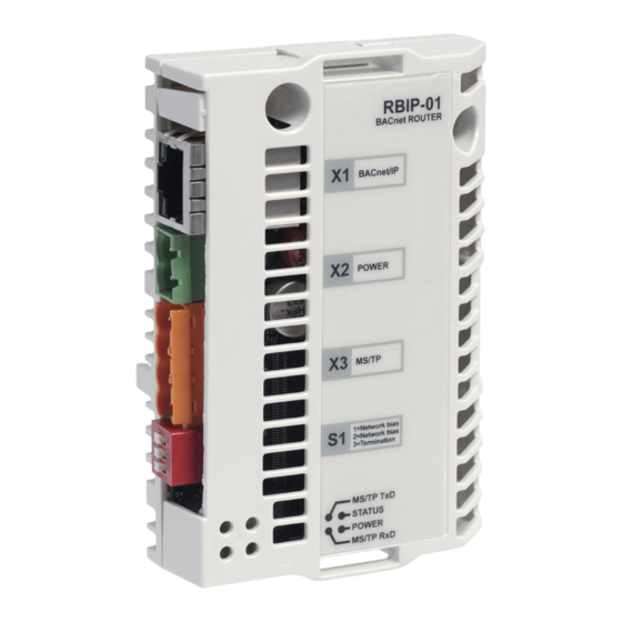
Page 35: Technical Data
Technical data RBIP-01 Enclosure: 34 mm CHASSIS RBIP-01 BACnet ROUTER BACnet/IP POWER MS/TP 1=Network bias 2=Network bias 3=Termination 62 mm Mounting: Into the option slot on the control board of the drive. Degree of protection: IP20 Power supply: 12...26 V DC / AC, 200 mA, internal fuse Resistors: •... - Page 36 Indicators: Six LEDs (POWER, MS/TP TxD, MS/TP RxD, STATUS, an orange and a green network LED). For more information on the LEDs, see the RBIP-01 BACnet/IP Router Module User’s Manual (3AUA0000040159 [English]) Connectors: • 2-pin connector for power supply • 4-pin connector for EIA-485 •...
-
Page 37: Connection Examples
Connection examples This chapter includes connection examples of the RBIP-01 BACnet/IP Router Module and the ACH550 devices in the MS/TP network. Notes: • Terminate the EIA-485 network at both ends either using external 120 resistors or using the router module’s S1.3 DIP switch if the router module is located at the end of the EIA-485 segment. - Page 38 Connection examples...
- Page 39 Connection examples...
- Page 40 Connection examples...
-
Page 41: Further Information
Product and service inquiries Address any inquiries about the product to your local ABB representative, quoting the type designation and serial number of the unit in question. A listing of ABB sales, support and service contacts can be found by navigating to www.abb.com/drives selecting Sales, Support and Service network. - Page 42 ABB Oy ABB Inc. Drives Automation Technologies P.O. Box 184 Drives & Motors FIN-00381 HELSINKI 16250 West Glendale Drive FINLAND New Berlin, WI 53151 USA Telephone +358 10 22 11 Telephone 262 785-3200 +358 10 22 22681 1-800-HELP-365 www.abb.com/drives 262 780-5135...