Table of Contents
Advertisement
Quick Links
Advertisement
Table of Contents

Related Manuals for ABB BCU-01


Summary of Contents for ABB BCU-01
- Page 1 — ABB INDUSTRIAL DRIVES Hardware manual BCU-01/11 control units...
- Page 2 You can find manuals and other product documents in PDF format on the Internet. See section on the inside of the back cover. For manuals not available in the Document library on the Internet Document library, contact your local ABB representative. © 2023 ABB Oy. All rights reserved. 3AXD50000034055 Rev B...
-
Page 3: Table Of Contents
Providing feedback on ABB Drives manuals ........ -
Page 5: Bcu-01/11 Control Units
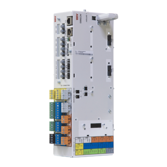
Hardware description The BCU-01/11 are control units used for controlling converters via fiber optic links. It contains integrated branching unit functionality for collecting and storing real- time data from the converter modules to help fault tracing and analysis. The data is stored in a secure data card. -
Page 6: Fiber Optic Connections
6 BCU-01/11 control units the SDHC memory card inserted into the SD CARD slot and can be analyzed by ABB service personnel. The drive-to-drive link (XD2D) is a daisy-chained RS-485 transmission line that allows basic master/follower communication with one master and multiple followers. The control unit has also one option slot for connecting the RDCO DDCS communication option board. - Page 7 BCU-01/11 control units 7...
- Page 8 8 BCU-01/11 control units The label describes the location of the I/O connectors and has the same colors as Label the connectors.
- Page 9 BCU-01/11 control units 9 Description I/O connector Analog input Analog output Digital input and digital start interlock XDIO Digital input/output XD2D Drive-to-drive link XD24 +24 V output for digital input XPOW External power input XRO1 Relay output 1 XRO2 Relay output 2...
-
Page 10: The 7-Segment Display
10 BCU-01/11 control units Description Miscellaneous + Battery Real-time clock battery The 7-segment display The following table describes the indications of the 7-segment display on the control unit. Multicharacter indications are displayed as repeated sequences of characters. “U” is indicated shortly before “o”. -
Page 11: Mechanical Installation
BCU-01/11 control units 11 Mechanical installation WARNING! Do not install the control unit in the immediate vicinity of electromagnetic disturbance sources, such as relays, contactors, brake choppers, power and motor cabling. The minimum recommended distance from such components is 200 mm. We recommend to install metallic screening between the control unit and the source of disturbance. -
Page 12: Vertical Din Rail Mounting
12 BCU-01/11 control units Vertical DIN rail mounting Fasten the latch to the back of the control unit with four screws. 2. Clip the control unit to the rail as shown below. -
Page 13: Horizontal Din Rail Mounting
BCU-01/11 control units 13 Horizontal DIN rail mounting Fasten the latches to the back of the control unit with four screws. 2. Clip the control unit to the rail as shown below. Electrical installation Safety instructions for WARNING! Obey the safety instructions given in ACS860 multidrive cabinets and modules [3AXD50000034060 (English)]. -
Page 14: Fault Tracing
14 BCU-01/11 control units Fault tracing LEDs BATT OK When on, the battery voltage of the real time clock is OK (higher than 2.8 V). When off, • battery voltage is below 2.8 V, • battery is missing, or •... -
Page 15: Maintenance
BCU-01/11 control units 15 Maintenance Replacing the real-time clock battery Replace the real-time clock battery if the BATT LED is not illuminated when the Fault tracing control unit is powered. For information on the LED, see on page See the appropriate documentation: drive or inverter module See A in figure hardware manual. -
Page 16: Replacing The Control Unit
16 BCU-01/11 control units Replacing the control unit Installing the control unit See section on page If the control unit has been installed vertically, remove the end bracket. 2. Remove the control unit from the rail. 3. Undo the four fastening screws with which the latch has been fastened to the back of the control unit. -
Page 17: Technical Data
BCU-01/11 control units 17 Technical data Connector data Power supply Connector pitch 5 mm, wire size 2.5 mm (XPOW) 24 V (±10%) DC, 2 A External power input. Two supplies can be connected for redundancy. Relay outputs RO1…RO3 Connector pitch 5 mm, wire size 2.5 mm (XRO1…XRO3) - Page 18 18 BCU-01/11 control units Reference voltage for Connector pitch 5 mm, wire size 2.5 mm analog inputs +VREF and 10 V ±1% and –10 V ±1%, 1…10 kohm load -VREF Maximum output current: 10 mA (XAI:1 and XAI:2) Analog inputs AI1 and Connector pitch 5 mm, wire size 2.5 mm...
-
Page 19: Ground Isolation Diagram
BCU-01/11 control units 19 Ground isolation diagram XPOW +24VI +24VI +VREF -VREF Common mode voltage AGND between each AI input AI1+ and AGND is +30 V AI1- AI2+ AI2- AGND AGND XD2D BGND SHIELD XRO1, XRO2, XD24 +24VD DICOM +24VD... -
Page 20: Dimensions
20 BCU-01/11 control units Dimensions Height Width Width with Depth Depth with Depth with connector memory unit memory unit and latch 12.2 4.92 139 5.47 4.33 4.53 Battery Real-time clock battery BR2032 Protection classes Degree of protection IP10 (IEC/EN 60529) -
Page 21: Cyber Security Disclaimer
ABB and its affiliates are not liable for damages and/or losses related to such security breaches, any unauthorized access, interference, intrusion, leakage and/or theft of data or information. - Page 22 22 BCU-01/11 control units Dimension drawing Note: If no any special notes, all the dimensions in manual use metric unit (mm). Please contact ABB if you have any question related to drawings.
-
Page 23: Further Information
Product and service inquiries Address any inquiries about the product to your local ABB representative, quoting the type designation and serial number of the unit in question. A listing of ABB sales, support and service contacts can be found by navigating to www.abb.com/searchchannels. - Page 24 Contact us www.abb.com/drives www.abb.com/solar www.abb.com/windpower www.abb.com/drivespartners 3AXD50000034055 Rev B (EN) 2023-10-15...