ABB REC650 Applications Manual
Hide thumbs
Also See for REC650:
- Technical manual (700 pages) ,
- Commissioning manual (118 pages) ,
- Product manual (109 pages)
Table of Contents
Advertisement
Quick Links
Advertisement
Table of Contents

Related Manuals for ABB REC650


Summary of Contents for ABB REC650
- Page 1 ® Relion 650 series Bay control REC650 ANSI Application manual...
- Page 3 Document ID: 1MRK 511 286-UUS Issued: October 2016 Revision: A Product version: 1.3 © Copyright 2013 ABB. All rights reserved...
- Page 4 Copyright This document and parts thereof must not be reproduced or copied without written permission from ABB, and the contents thereof must not be imparted to a third party, nor used for any unauthorized purpose. The software and hardware described in this document is furnished under a license and may be used or disclosed only in accordance with the terms of such license.
- Page 5 This document has been carefully checked by ABB but deviations cannot be completely ruled out. In case any errors are detected, the reader is kindly requested to notify the manufacturer.
- Page 6 (EMC Directive 2004/108/EC) and concerning electrical equipment for use within specified voltage limits (Low-voltage directive 2006/95/EC). This conformity is the result of tests conducted by ABB in accordance with the product standard EN 60255-26 for the EMC directive, and with the product standards EN 60255-1 and EN 60255-27 for the low voltage directive.
-
Page 7: Table Of Contents
Bus coupler in a solidly grounded network........35 Bus coupler in a high impedance grounded network......36 Section 3 REC650 setting examples...........39 Setting example when REC650 is used as back-up protection in a transformer protection application............39 Calculating general settings for analogue inputs 8I 2U..... 40 Calculating settings for global base values GBASVAL......42... - Page 8 Table of contents Calculating settings for step 1............44 Calculating settings for four step phase overcurrent protection 3- phase output, LV-side OC4PTOC (51_67)........46 Calculating general settings............47 Calculating settings for step 1 ............. 47 Calculating settings for step 4............48 Calculating settings for four step residual overcurrent protection, zero or negative sequence direction HV-side EF4PTOC (51N/67N).50 Calculating general settings............
- Page 9 Table of contents Local HMI....................77 Display....................77 LEDs....................79 Keypad....................80 Local HMI functionality..............82 Protection and alarm indication............ 82 Parameter management ..............83 Front communication..............83 Single-line diagram...............84 Section 6 Current protection..............87 Instantaneous phase overcurrent protection 3-phase output PHPIOC (50)...................87 Identification..................87 Application..................
- Page 10 Table of contents Application..................118 Setting guidelines................120 Thermal overload protection, one time constant Fahrenheit/Celsius LFPTTR/LCPTTR (26)................128 Identification..................128 Application..................129 Setting guidelines................129 Breaker failure protection 3-phase activation and output CCRBRF ( 50BF)....................130 Identification..................130 Application..................130 Setting guidelines................131 Stub protection STBPTOC (50STB).............
- Page 11 Table of contents Application..................151 Setting guidelines................152 Equipment protection, such as for motors and generators..152 Disconnected equipment detection..........152 Power supply quality ..............152 Voltage instability mitigation............153 Backup protection for power system faults.........153 Settings for Two step undervoltage protection......153 Two step overvoltage protection OV2PTOV (59).........
- Page 12 Table of contents Current circuit supervision CCSRDIF (87)..........171 Identification..................171 Application..................171 Setting guidelines................172 Fuse failure supervision SDDRFUF............172 Identification..................172 Application..................172 Setting guidelines................173 General..................173 Setting of common parameters..........173 Negative sequence based............174 Zero sequence based..............175 Delta V and delta I ..............176 Dead line detection..............176 Breaker close/trip circuit monitoring TCSSCBR........
- Page 13 Table of contents Initiate auto-reclosing from CB open information....... 201 Blocking of the autorecloser............202 Control of the auto-reclosing open time ........202 Long trip signal................202 Maximum number of reclosing shots..........202 3-phase reclosing, one to five shots according to setting NoOfShots..................
- Page 14 Table of contents Signals in single breaker arrangement........238 Signals in double-breaker arrangement........242 Signals in breaker and a half arrangement.........244 Interlocking for bus-coupler bay ABC_BC (3)........245 Application.................. 245 Configuration................246 Signals from all feeders.............. 246 Signals from bus-coupler............249 Configuration setting..............250 Interlocking for breaker-and-a-half diameter BH (3)......
- Page 15 Table of contents Setting guidelines................266 Automation bits AUTOBITS..............267 Identification..................267 Application..................267 Setting guidelines................267 Section 11 Logic..................269 Tripping logic common 3-phase output SMPPTRC (94).......269 Identification..................269 Application..................269 Three-pole tripping ..............269 Lock-out..................270 Blocking of the function block............. 270 Setting guidelines................
- Page 16 Table of contents Identification..................280 Application..................280 Settings....................280 Elapsed time integrator with limit transgression and overflow supervision TEIGGIO................280 Identification..................280 Application..................281 Setting guidelines................281 Section 12 Monitoring................283 IEC61850 generic communication I/O functions SPGGIO....283 Identification..................283 Application..................283 Setting guidelines................283 IEC61850 generic communication I/O functions 16 inputs SP16GGIO283 Identification..................
- Page 17 Table of contents Binary input signals..............299 Analog input signals..............300 Sub-function parameters............300 Consideration................301 Measured value expander block MVEXP..........302 Identification..................302 Application..................302 Setting guidelines................302 Fault locator LMBRFLO................ 302 Identification..................302 Application..................303 Setting guidelines................303 Connection of analog currents............305 Station battery supervision SPVNZBAT..........
- Page 18 Table of contents Setting guidelines................320 DNP3 protocol..................321 IEC 60870-5-103 communication protocol........... 321 IEC 61850-8-1 redundant station bus communication......321 Application.................... 322 Setting guidelines................. 323 Section 15 Basic IED functions............325 Self supervision with internal event list ..........325 Identification..................325 Application..................
- Page 19 Table of contents Application..................335 Setting guidelines................335 Summation block 3 phase 3PHSUM............ 338 Identification..................338 Application..................338 Setting guidelines................338 Global base values GBASVAL............. 339 Identification..................339 Application..................339 Setting guidelines................339 Authority check ATHCHCK..............340 Identification..................340 Application..................340 Authorization handling in the IED..........
- Page 20 Table of contents Current transformers according to IEC 61869-2, class PX, PXR (and old IEC 60044-6, class TPS and old British Standard, class X)..........352 Current transformers according to ANSI/IEEE......352 Voltage transformer requirements............353 SNTP server requirements..............354 SNTP server requirements.............. 354 Section 17 Glossary................
-
Page 21: Section 1 Introduction
Section 1 1MRK 511 286-UUS A Introduction Section 1 Introduction This manual The application manual contains application descriptions and setting guidelines sorted per function. The manual can be used to find out when and for what purpose a typical protection function can be used. The manual can also provides assistance for calculating settings. -
Page 22: Product Documentation
Section 1 1MRK 511 286-UUS A Introduction Product documentation 1.3.1 Product documentation set Engineering manual Installation manual Commissioning manual Operation manual Application manual Technical manual Communication protocol manual IEC07000220-3-en.vsd IEC07000220 V3 EN Figure 1: The intended use of manuals throughout the product lifecycle The engineering manual contains instructions on how to engineer the IEDs using the various tools available within the PCM600 software. -
Page 23: Document Revision History
Document revision history Document revision/date History -/March 2013 First release A/October 2016 Minor corrections made 1.3.3 Related documents Documents related to REC650 Identity number Application manual 1MRK 511 286-UUS Technical manual 1MRK 511 287-UUS Commissioning manual 1MRK 511 288-UUS Product Guide... -
Page 24: Symbols And Conventions
Section 1 1MRK 511 286-UUS A Introduction 650 series manuals Identity number Communication protocol manual, DNP 3.0 1MRK 511 280-UUS Communication protocol manual, IEC 61850–8–1 1MRK 511 281-UUS Communication protocol manual, IEC 60870-5-103 1MRK 511 282-UUS Cyber Security deployment guidelines 1MRK 511 285-UUS Point list manual, DNP 3.0 1MRK 511 283-UUS... -
Page 25: Document Conventions
Section 1 1MRK 511 286-UUS A Introduction The tip icon indicates advice on, for example, how to design your project or how to use a certain function. Although warning hazards are related to personal injury, it is necessary to understand that under certain operational conditions, operation of damaged equipment may result in degraded process performance leading to personal injury or death. -
Page 27: Section 2 Application
Application REC650 application REC650 is used for the control, protection and monitoring of different types of bays in power networks. The IED is especially suitable for applications in control systems with distributed control IEDs in all bays with high demands on reliability. It is suitable for the control of all apparatuses in single busbar single CB, double busbar single CB switchgear arrangement. - Page 28 The graphical configuration tool ensures simple and fast testing and commissioning. 132 kV Bus REC650-A01A – Single Busbar Single breaker 10AI (4I+1I+5U) Control...
- Page 29 Section 2 1MRK 511 286-UUS A Application REC650-A02A – Double Busbar Single breaker 10AI (4I+1I+5U) 132 kV Bus Control Control Control S CILO S CSWI S XSWI Control Control Control 132kV/ S CILO S CSWI S XSWI 110V 132kV/ 110V Meter.
- Page 30 Section 2 1MRK 511 286-UUS A Application 1189G 2189G REC650-A07A – Bus Coupler single breaker 10AI (4I+6U) 132 kV Bus Control Control Control S CILO S CSWI S XSWI Control Control Control 132kV/ S CILO S CSWI S XSWI 110V...
-
Page 31: Available Functions
Section 2 1MRK 511 286-UUS A Application Available functions 2.2.1 Control and monitoring functions IEC 61850 or Function ANSI Function description name Control SESRSYN Synchrocheck, energizing check, and 0–1 synchronizing SMBRREC Autorecloser for 3–phase operation 0–1 SLGGIO Logic Rotating Switch for function selection and LHMI presentation VSGGIO Selector mini switch... - Page 32 Section 2 1MRK 511 286-UUS A Application IEC 61850 or Function ANSI Function description name DB_BUS_B Interlocking for double CB bay DB_LINE Interlocking for double CB bay ABC_LINE Interlocking for line bay AB_TRAFO Interlocking for transformer bay SCSWI Switch controller SXCBR Circuit breaker SXSWI...
- Page 33 Section 2 1MRK 511 286-UUS A Application IEC 61850 or Function ANSI Function description name ORQT Configurable logic blocks Q/T 0–120 INVERTERQT Configurable logic blocks Q/T 0–120 XORQT Configurable logic blocks Q/T 0–40 SRMEMORYQT Configurable logic blocks Q/T 0–40 RSMEMORYQT Configurable logic blocks Q/T 0–40 TIMERSETQT...
- Page 34 Section 2 1MRK 511 286-UUS A Application IEC 61850 or Function ANSI Function description name AM_S_P4 Function block for service values presentation of secondary analog inputs 600AIM CNTGGIO Event counter L4UFCNT Event counter with limit supervision DRPRDRE Disturbance report AnRADR Analog input signals BnRBDR Binary input signals...
-
Page 35: Back-Up Protection Functions
Section 2 1MRK 511 286-UUS A Application 2.2.2 Back-up protection functions IEC 61850 or ANSI Function description Function name Current protection PHPIOC Instantaneous phase overcurrent protection, 3–phase 0–1 output OC4PTOC 51/67 Four step phase overcurrent protection, 3-phase 0–1 output EFPIOC Instantaneous residual overcurrent protection 0–1 EF4PTOC... -
Page 36: Station Communication
Section 2 1MRK 511 286-UUS A Application 2.2.3 Station communication IEC 61850 or Function ANSI Function description name Station communication IEC61850-8-1 IEC 61850 communication protocol DNPGEN DNP3.0 communication general protocol RS485DNP DNP3.0 for RS-485 communication protocol CH1TCP DNP3.0 for TCP/IP communication protocol CH2TCP DNP3.0 for TCP/IP communication protocol CH3TCP... -
Page 37: Basic Ied Functions
Section 2 1MRK 511 286-UUS A Application IEC 61850 or Function ANSI Function description name ACTIVLOG Activity logging parameters SECALARM Component for mapping security events on protocols such as DNP3 and IEC103 AGSAL Generic security application component GOOSEDPRCV GOOSE function block to receive a double point value GOOSEINTRCV GOOSE function block to receive an integer... -
Page 38: Rec650 Application Examples
DOSLAN1 Denial of service, frame rate control for LAN1A and LAN1B ports DOSSCKT Denial of service, socket flow control REC650 application examples 2.3.1 Adaptation to different applications The IED has pre-defined configurations mainly for sub-station control applications. There is however the possibility to integrate back-up protection functions in the IED. In sub-... -
Page 39: Single Breaker Line Bay, Single Or Double Busbar, In High Impedance Grounded Network
Section 2 1MRK 511 286-UUS A Application • Close in line short circuits: For close in faults the instantaneous phase overcurrent protection should be used. As the fault current is often high at this fault case fast tripping is essential. It is however important to base the setting on fault calculations considering different operational states. - Page 40 Section 2 1MRK 511 286-UUS A Application calculations considering different operational states as well as time delay co- ordination with other protections in the system. As a second protection a residual voltage protection is often used. • Failure of the circuit beaker to interrupt fault current after protection trip. The breaker failure protection function is essential in a protection system using local redundancy.
-
Page 41: Bus Coupler In A Solidly Grounded Network
Section 2 1MRK 511 286-UUS A Application Function Application 1 Application 2 Directional over-power protection GOPPDOP Application dependent Application dependent (32) Negative sequence based overcurrent Application dependent Application dependent protection DNSPTOC (46) Two step undervoltage protection UV2PTUV Application dependent Application dependent (27) Two step overvoltage protection OV2PTOV Application dependent... -
Page 42: Bus Coupler In A High Impedance Grounded Network
Section 2 1MRK 511 286-UUS A Application function as well as different time delay characteristics. It is important to base the setting on fault calculations considering different operational states as well as time delay coordination with other protections in the system. •... - Page 43 Section 2 1MRK 511 286-UUS A Application Table 2: Functionality table Function Application 3 Application 4 Instantaneous phase overcurrent protection, 3-phase output PHPIOC (50) Disabled Disabled Four step phase overcurrent protection, 3- phase output OC4PTOC (51_67) Disabled Disabled Instantaneous residual overcurrent Enabled Enabled protection EFPIOC(50N)
- Page 44 Section 2 1MRK 511 286-UUS A Application Function Application 3 Application 4 Fuse failure supervision SDDRFUF Enabled Enabled Breaker close/trip circuit monitoring Enabled Enabled TCSSCBR Synchrocheck, energizing check, and Application dependent Application dependent synchronizing SESRSYN (25) Autorecloser for 3-phase operation Disabled Disabled SMBRREC (79)
-
Page 45: Section 3 Rec650 Setting Examples
1MRK 511 286-UUS A REC650 setting examples Section 3 REC650 setting examples Setting example when REC650 is used as back-up protection in a transformer protection application The application example has a 145/22 kV transformer as shown in figure 5. 145 kV... -
Page 46: Calculating General Settings For Analogue Inputs 8I 2U
Section 3 1MRK 511 286-UUS A REC650 setting examples Item Data High positive sequence source impedance at the HV j10 Ω (about 2 100 MVA) side Low positive sequence source impedance at the HV j3.5 Ω (about 6 000 MVA) - Page 47 Section 3 1MRK 511 286-UUS A REC650 setting examples The 22 kV phase-to-phase (A - B) VT is connected to input 9. The 22 kV open delta connected VT (residual voltage) is connected to input 10. Set the 145 kV current transformer input 1.
-
Page 48: Calculating Settings For Global Base Values Gbasval
Section 3 1MRK 511 286-UUS A REC650 setting examples 3.1.2 Calculating settings for global base values GBASVAL Each function uses primary base values as a reference for the settings. The base values are defined in Global base values for setting GBASVAL function. It is possible to include up to GBASVAL function. -
Page 49: Calculating Settings For Four Step Phase Overcurrent Protection
Section 3 1MRK 511 286-UUS A REC650 setting examples 1.83 × × × 3 (3.5 0.12) (Equation 1) GUID-662F8080-2FA3-47D9-B030-CDB4D502DB53 V2 EN The dynamic overreach, due to fault current DC-component, shall be considered in the setting. This factor is less that 5 %. The setting is chosen with a safety margin of 1.2:... -
Page 50: Calculating Settings For Step 1
Section 3 1MRK 511 286-UUS A REC650 setting examples For the choice of the time delay characteristic IEC Normal inverse is used in this network. 3.1.4.2 Calculating settings for step 1 Set Pickup1 to 140% of IBase (334 A primary current) The first requirement is that the phase overcurrent protection shall never trip for load current during the extreme high load situations. - Page 51 Section 3 1MRK 511 286-UUS A REC650 setting examples æ ö × 0.23 ç ÷ è ø (Equation 3) GUID-FA8FA533-48E3-45FA-A22A-584CD0F754BF V1 EN The transformer impedance referred to 22 kV level is: × 0.12 0.97 (Equation 4) GUID-78CEC42F-9A02-411B-B6D3-95017467242B V1 EN The fault current can be calculated as follows: 22000 ×...
-
Page 52: Calculating Settings For Four Step Phase Overcurrent Protection
Section 3 1MRK 511 286-UUS A REC650 setting examples IEC09000451 V1 EN Figure 7: Inverse time operation characteristics for selectivity 3.1.5 Calculating settings for four step phase overcurrent protection 3-phase output, LV-side OC4PTOC (51_67) The 22 kV phase overcurrent protection has the following purpose: •... -
Page 53: Calculating General Settings
Section 3 1MRK 511 286-UUS A REC650 setting examples faults, fault points and switching states in the network. Although it is possible to make manual calculations of the different faults it is recommended to use computer based fault calculations. The following principle for the phase overcurrent protection is proposed: •... -
Page 54: Calculating Settings For Step 4
Section 3 1MRK 511 286-UUS A REC650 setting examples æ ö × 0.23 ç ÷ è ø (Equation 7) GUID-A4805F4D-20EC-4B39-A39D-925513515FA5 V1 EN The transformer impedance, referred to 22 kV level, is: × 0.12 0.97 (Equation 8) GUID-CB0D94B6-5BFA-42EB-AE4A-B0EE898A0D78 V1 EN Calculation of a phase-to-phase short circuit at this busbar: 22000 / 3 ×... - Page 55 Section 3 1MRK 511 286-UUS A REC650 setting examples 51_67 145 kV REC650 22 kV Ph-Ph ANSI11000124-1-en.vsd ANSI11000124 V1 EN Figure 8: Fault calculation for phase overcurrent protection A phase-phase-ground short circuit is applied. In this calculation the short circuit power of the feeder shall be minimized (the source impedance maximized).
-
Page 56: Calculating Settings For Four Step Residual Overcurrent Protection Zero Or Negative Sequence Direction Hv-Side Ef4Ptoc (51N/67N)
Section 3 1MRK 511 286-UUS A REC650 setting examples difference between the inverse time curves is 0.4 s. With the setting TD4= 0.15 the time margin between the characteristics is about 0.4 s as shown in figure 9. IEC09000453 V1 EN... -
Page 57: Calculating General Settings
Section 3 1MRK 511 286-UUS A REC650 setting examples The residual overcurrent protection is more difficult to set as the ground-fault current is highly dependent on the network configuration of the power system. In order to achieve settings that assure selective fault clearance, a large number of calculations have to be made with different fault locations, different switching states in the system and different ground-fault types. -
Page 58: Calculating Settings For Step 1
Section 3 1MRK 511 286-UUS A REC650 setting examples Set GlobalBaseSel to 1, IBase = 240 A Set DirModeSel1, DirModeSel2 and DirModeSel4 to Non-directional Set DirModeSel3 to Disabled 3.1.6.2 Calculating settings for step 1 Set the operating residual current level and time delay Set Pickup1 to 689% of IBase, corresponding to 1650 A Faults are applied at the 145 kV busbar as shown in figure 10. - Page 59 Section 3 1MRK 511 286-UUS A REC650 setting examples × × 3 145 × × × × 42 2 3.5 × × (Equation 14) GUID-CC2E2412-4939-4285-A491-FCCC0AE0F939-ANSI V1 EN The residual current from the transformer during a single phase-ground-fault and with minimum short circuit power is: ×...
-
Page 60: Calculating Settings For Step 2
Section 3 1MRK 511 286-UUS A REC650 setting examples The calculations show that the largest residual current from the transformer = 1.2 To assure selectivity the setting must fulfil: ≥ 1.2 · k · 3I high,set 0 max which gives about 1 500 A ,where k is the transient overreach (due to the fault current DC-component) of the overcurrent function. -
Page 61: Calculating Settings For Step 4
Section 3 1MRK 511 286-UUS A REC650 setting examples 3.1.6.4 Calculating settings for step 4 Set Pickup4 to 42 % of IBase, corresponding to 100 A The current setting of step 4 should be chosen according to standard procedure in the grid. - Page 62 Section 3 1MRK 511 286-UUS A REC650 setting examples system. The neutral point resistor gives a 10 A ground-fault current during a zero resistance ground-fault. This means that the resistance is 22000 1270 (Equation 18) GUID-4ECDF824-B17E-436D-A668-ACA06BB375F7 V2 EN The total zero sequence impedance of the 22 kV system is:...
-
Page 63: Calculating Settings For Hv-Side Breaker Failure Protection Ccrbrf (50Bf)
Section 3 1MRK 511 286-UUS A REC650 setting examples 3.1.8 Calculating settings for HV-side breaker failure protection, CCRBRF (50BF) The breaker failure protection can use either the position indication of the circuit breaker or measure the current going through the CT in order to detect correct breaker functioning. -
Page 64: Calculating Settings For Lv-Side Breaker Failure Protection Ccrbrf (50Bf)
Section 3 1MRK 511 286-UUS A REC650 setting examples Protection operate time Normal t cbopen The fault Retrip delay t1 after re-trip cbopen occurs BFPreset Margin Minimum back-up trip delay t2 Critical fault clearance time for stability Time Trip and Start en05000479.vsd... - Page 65 Section 3 1MRK 511 286-UUS A REC650 setting examples • 1 out of 3: at least one of the three-phase current shall be larger than the set level to detect failure to break • 1 out of 4: at least one of the three-phase current and the residual current shall be larger than the set level to detect failure to break •...
- Page 66 Section 3 1MRK 511 286-UUS A REC650 setting examples Application manual...
-
Page 67: Introduction
Section 4 1MRK 511 286-UUS A Analog inputs Section 4 Analog inputs Introduction Analog input channels in the IED must be set properly in order to get correct measurement results and correct protection operations. For power measuring and all directional and differential functions the directions of the input currents must be defined in order to reflect the way the current transformers are installed/connected in the field ( primary and secondary connections ). -
Page 68: Relationships Between Setting Parameter Base Current, Ct Rated Primary Current And Minimum Pickup Of A Protection Ied
Section 4 1MRK 511 286-UUS A Analog inputs The phase reference does not work if the current channel is not available. For example, when the circuit breaker is opened and no current flows. Although the phase angle difference between the different phases is firm, the whole system appears to be rotating when the measurement functions are observed. -
Page 69: Example 1
Section 4 1MRK 511 286-UUS A Analog inputs A positive value of current, power, and so on (forward) means that the quantity has a direction towards the object. - A negative value of current, power, and so on (reverse) means a direction away from the object. See figure 15. Definition of direction Definition of direction for directional functions... -
Page 70: Example 2
Section 4 1MRK 511 286-UUS A Analog inputs Line Transformer Line Reverse Forward Definition of direction for directional functions Transformer protection Line protection Setting of current input: Setting of current input: Setting of current input: Set parameter Set parameter Set parameter CT_WyePoint with CT_WyePoint with CT_WyePoint with... - Page 71 Section 4 1MRK 511 286-UUS A Analog inputs ANSI05000460 V2 EN Application manual...
-
Page 72: Examples On How To Connect, Configure And Set Ct Inputs For Most Commonly Used Ct Connections
Section 4 1MRK 511 286-UUS A Analog inputs Transformer Line Reverse Forward Definition of direction for directional functions Transformer Line protection protection Setting of current input: Setting of current input: Setting of current input: Set parameter Set parameter Set parameter CT_WyePoint with CT_WyePoint with CT_WyePoint with... -
Page 73: Example On How To Connect A Wye Connected Three-Phase Ct Set To The Ied
Section 4 1MRK 511 286-UUS A Analog inputs (H2) (H1) S2 (X2) S1 (X1) S2 (X2) S1 (X1) (H2) (H1) en06000641.vsd IEC06000641 V1 EN Figure 18: Commonly used markings of CT terminals Where: is symbol and terminal marking used in this document. Terminals marked with a dot indicates the primary and secondary winding terminals with the same (that is, positive) polarity b) and c) are equivalent symbols and terminal marking used by IEC (ANSI) standard for CTs. - Page 74 Section 4 1MRK 511 286-UUS A Analog inputs For correct terminal designations, see the connection diagrams valid for the delivered IED. SMAI_20 CT 600/5 Star Connected ANSI3000002-2-en.vsd Protected Object ANSI13000002 V2 EN Figure 19: Wye connected three-phase CT set with wye point towards the protected object Where: The drawing shows how to connect three individual phase currents from a wye connected three- phase CT set to the three CT inputs of the IED.
- Page 75 Section 4 1MRK 511 286-UUS A Analog inputs These three connections are the links between the three current inputs and the three input channels of the preprocessing function block 4). Depending on the type of functions, which need this current information, more than one preprocessing block might be connected in parallel to the same three physical CT inputs.
-
Page 76: Setting Of Voltage Channels
Section 4 1MRK 511 286-UUS A Analog inputs SMAI_20_2 BLOCK AI3P REVROT ^GRP2L1 ^GRP2L2 ^GRP2L3 CT 800/1 ^GRP2N Star Connected ANSI11000026-4-en.vsd Protected Object ANSI11000026 V4 EN Figure 20: Wye connected three-phase CT set with its star point away from the protected object In the example in figure 20 case everything is done in a similar way as in the above... -
Page 77: Example
Section 4 1MRK 511 286-UUS A Analog inputs 4.2.4.1 Example Consider a VT with the following data: 132kV 120V (Equation 21) EQUATION1937 V1 EN The following setting should be used: VTprim=132 (value in kV) VTsec=120 (value in V) 4.2.4.2 Examples how to connect, configure and set VT inputs for most commonly used VT connections Figure defines the marking of voltage transformer terminals commonly used around... -
Page 78: Examples On How To Connect A Three Phase-To-Ground Connected Vt To The Ied
Section 4 1MRK 511 286-UUS A Analog inputs • 100 V • 110 V • 115 V • 120 V • 230 V The IED fully supports all of these values and most of them will be shown in the following examples. -
Page 79: Example On How To Connect A Phase-To-Phase Connected Vt To The Ied
Section 4 1MRK 511 286-UUS A Analog inputs Where: shows how to connect three secondary phase-to-ground voltages to three VT inputs on the IED is the TRM where these three voltage inputs are located. For these three voltage inputs, the following setting values shall be entered: VTprim = 66 kV VTsec = 110 V... - Page 80 Section 4 1MRK 511 286-UUS A Analog inputs For correct terminal designations, see the connection diagrams valid for the delivered IED. 13.8 SMAI_20 ANSI11000032-2-en.vsd ANSI11000032 V2 EN Figure 23: A Phase-to-phase connected VT Application manual...
- Page 81 Section 4 1MRK 511 286-UUS A Analog inputs Where: shows how to connect the secondary side of a phase-to-phase VT to the VT inputs on the IED is the TRM or AIM where this voltage input is located. The following setting values shall be entered: VTprim =13.8 kV VTsec =120 V are three connections, which connects these three voltage inputs to three input channels of the...
-
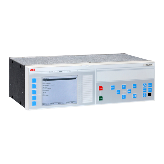
Page 83: Section 5 Local Human-Machine Interface
Section 5 1MRK 511 286-UUS A Local human-machine interface Section 5 Local human-machine interface Local HMI ANSI12000175 V1 EN Figure 24: Local human-machine interface The LHMI of the IED contains the following elements: • Display (LCD) • Buttons • LED indicators •... - Page 84 Section 5 1MRK 511 286-UUS A Local human-machine interface IEC13000063-1-en.vsd IEC13000063 V1 EN Figure 25: Display layout 1 Path 2 Content 3 Status 4 Scroll bar (appears when needed) The function button panel shows on request what actions are possible with the function buttons.
-
Page 85: Leds
Section 5 1MRK 511 286-UUS A Local human-machine interface ANSI12000025-1-en.vsd ANSI12000025 V1 EN Figure 26: Function button panel The alarm LED panel shows on request the alarm text labels for the alarm LEDs. Three alarm LED pages are available. GUID-D20BB1F1-FDF7-49AD-9980-F91A38B2107D V1 EN Figure 27: Alarm LED panel The function button and alarm LED panels are not visible at the same time. -
Page 86: Keypad
Section 5 1MRK 511 286-UUS A Local human-machine interface There are 3 separate pages of LEDs available. The 15 physical three-color LEDs in one LED group can indicate 45 different signals. Altogether, 135 signals can be indicated since there are three LED groups. The LEDs can be configured with PCM600 and the operation mode can be selected with the LHMI or PCM600. - Page 87 Section 5 1MRK 511 286-UUS A Local human-machine interface ANSI11000247 V2 EN Figure 28: LHMI keypad with object control, navigation and command push buttons and RJ-45 communication port 1...5 Function button Close Open Escape Left Down Right User Log on Enter Remote/Local Uplink LED...
-
Page 88: Local Hmi Functionality
Section 5 1MRK 511 286-UUS A Local human-machine interface 5.1.4 Local HMI functionality 5.1.4.1 Protection and alarm indication Protection indicators The protection indicator LEDs are Normal, Pickup and Trip. Table 4: Normal LED (green) LED state Description Auxiliary supply voltage is disconnected. Normal operation. -
Page 89: Parameter Management
Section 5 1MRK 511 286-UUS A Local human-machine interface Table 7: Alarm indications LED state Description Normal operation. All activation signals are off. • Follow-S sequence: The activation signal is on. • LatchedColl-S sequence: The activation signal is on, or it is off but the indication has not been acknowledged. -
Page 90: Single-Line Diagram
Section 5 1MRK 511 286-UUS A Local human-machine interface GUID-D71BA06D-3769-4ACB-8A32-5D02EA473326 V1 EN Figure 29: RJ-45 communication port and green indicator LED 1 RJ-45 connector 2 Green indicator LED When a computer is connected to the IED front port with a crossed-over cable, the IED's DHCP server for the front interface assigns an IP address to the computer if DHCPServer = Enabled. - Page 91 Section 5 1MRK 511 286-UUS A Local human-machine interface ANSI11000181 V1 EN ANSI11000180 V1 EN Figure 30: Single-line diagram example (REC650) Application manual...
-
Page 93: Instantaneous Phase Overcurrent Protection 3-Phase Output Phpioc (50)
Section 6 1MRK 511 286-UUS A Current protection Section 6 Current protection Instantaneous phase overcurrent protection 3-phase output PHPIOC (50) 6.1.1 Identification Function description IEC 61850 IEC 60617 ANSI/IEEE C37.2 identification identification device number Instantaneous phase overcurrent PHPIOC protection 3-phase output 3I>>... -
Page 94: Setting Guidelines
Section 6 1MRK 511 286-UUS A Current protection operate very quickly for faults very close to the generation (and relay) point, for which very high fault currents are characteristic. The instantaneous phase overcurrent protection 3-phase output PHPIOC (50) can operate in 10 ms for faults characterized by very high currents. - Page 95 Section 6 1MRK 511 286-UUS A Current protection Fault ANSI09000022-1-en.vsd ANSI09000022 V1 EN Figure 31: Through fault current from A to B: I Then a fault in A has to be applied and the through fault current I has to be calculated, figure 32.
-
Page 96: Meshed Network With Parallel Line
Section 6 1MRK 511 286-UUS A Current protection The minimum primary setting (Is) for the instantaneous phase overcurrent protection 3- phase output is then: ³ × (Equation 24) EQUATION79 V3 EN The protection function can be used for the specific application only if this setting value is equal to or less than the maximum fault current that the IED has to clear, I in figure 33. - Page 97 Section 6 1MRK 511 286-UUS A Current protection A fault in C has to be applied, and then the maximum current seen from the IED (I ) on the healthy line (this applies for single-phase-to-ground and two-phase-to-ground faults) is calculated. Line 1 Fault Line 2...
-
Page 98: Identification
Section 6 1MRK 511 286-UUS A Current protection Four step phase overcurrent protection 3-phase output OC4PTOC (51/67) 6.2.1 Identification Function description IEC 61850 IEC 60617 ANSI/IEEE C37.2 identification identification device number Four step phase overcurrent protection OC4PTOC 51/67 3I> 3-phase output TOC-REVA V1 EN 6.2.2 Application... -
Page 99: Setting Guidelines
Section 6 1MRK 511 286-UUS A Current protection characteristics. The selectivity between different overcurrent protections is normally enabled by co-ordination between the function time delays of the different protections. To enable optimal co-ordination between all overcurrent protections, they should have the same time delay characteristic. -
Page 100: Settings For Steps 1 To 4
Section 6 1MRK 511 286-UUS A Current protection ANSI09000636-1-en.vsd ANSI09000636 V1 EN Figure 35: Directional function characteristic 1. RCA = Relay characteristic angle 55° 2. ROA = Relay operating angle 80° 3. Reverse 4. Forward 6.2.3.1 Settings for steps 1 to 4 n means step 1 and 4. - Page 101 Section 6 1MRK 511 286-UUS A Current protection Characteristn: Selection of time characteristic for step n. Definite time delay and different types of inverse time characteristics are available according to table 8. Step 2 and 3 are always definite time delayed. Table 8: Inverse time characteristics Curve name...
-
Page 102: Nd Harmonic Restrain
Section 6 1MRK 511 286-UUS A Current protection parameter the operation time of the step can never be shorter than the setting. Setting range: 0.000 - 60.000s in steps of 0.001s. Operate time tnMin IMinn Current IEC09000164-2 IEC09000164 V2 EN Figure 36: Minimum operate current and operation time for inverse time characteristics... - Page 103 Section 6 1MRK 511 286-UUS A Current protection 2ndHarmStab: The rate of 2nd harmonic current content for activation of the 2nd harmonic restrain signal, to block chosen steps. The setting is given in % of the fundamental frequency residual current. The setting range is 5 - 100% in steps of 1%. The default setting is 20% and can be used if a deeper investigation shows that no other value is needed..
- Page 104 Section 6 1MRK 511 286-UUS A Current protection Im ax ³ × Ipu 1.2 (Equation 29) EQUATION1262 V2 EN where: is a safety factor is the resetting ratio of the protection Imax is the maximum load current The maximum load current on the line has to be estimated. There is also a demand that all faults, within the zone that the protection shall cover, must be detected by the phase overcurrent protection.
- Page 105 Section 6 1MRK 511 286-UUS A Current protection ³ × × high (Equation 32) EQUATION1265 V1 EN where: is a safety factor is a factor that takes care of the transient overreach due to the DC component of the fault current and can be considered to be less than 1.1 Iscmax is the largest fault current at a fault at the most remote point of the primary protection zone.
- Page 106 Section 6 1MRK 511 286-UUS A Current protection en05000204.wmf IEC05000204 V1 EN Figure 38: Fault time with maintained selectivity To assure selectivity between different protections, in the radial network, there have to be a minimum time difference Dt between the time delays of two protections. The minimum time difference can be determined for different cases.
- Page 107 Section 6 1MRK 511 286-UUS A Current protection have instantaneous function. The overcurrent protection of IED A1 must have a delayed function. The sequence of events during the fault can be described using a time axis, see figure 39. Feeder Time axis The fault Protection...
-
Page 108: Instantaneous Residual Overcurrent Protection Efpioc (50N)
Section 6 1MRK 511 286-UUS A Current protection D ³ (Equation 33) EQUATION1266 V1 EN where it is considered that: the operate time of overcurrent protection B1 is 40 ms the breaker open time is 100 ms the resetting time of protection A1 is 40 ms and the additional margin is 40 ms... - Page 109 Section 6 1MRK 511 286-UUS A Current protection GlobalBaseSel: Selects the global base value group used by the function to define (IBase), (VBase) and (SBase). The setting of the function is limited to the operate residual current to the protection (Pickup).
- Page 110 Section 6 1MRK 511 286-UUS A Current protection Fault ANSI09000023-1-en.vsd ANSI09000023 V1 EN Figure 41: Through fault current from B to A: I The function shall not operate for any of the calculated currents to the protection. The minimum theoretical current setting (Imin) will be: ³...
- Page 111 Section 6 1MRK 511 286-UUS A Current protection Line 1 Fault Line 2 ANSI09000025_2_en.vsd ANSI09000025 V2 EN Figure 42: Two parallel lines. Influence from parallel line to the through fault current: The minimum theoretical current setting (Imin) will in this case be: ³...
-
Page 112: Four Step Residual Overcurrent Protection, Zero, Negative Sequence Direction Ef4Ptoc (51N/67N)
Section 6 1MRK 511 286-UUS A Current protection Four step residual overcurrent protection, zero, negative sequence direction EF4PTOC (51N/67N) 6.4.1 Identification Function description IEC 61850 IEC 60617 ANSI/IEEE C37.2 identification identification device number Four step residual overcurrent EF4PTOC 51N/67N protection, zero or negative sequence direction IEC11000263 V1 EN 6.4.2... - Page 113 Section 6 1MRK 511 286-UUS A Current protection Non-directional/Directional function: In some applications the non-directional functionality is used. This is mostly the case when no fault current can be fed from the protected object itself. In order to achieve both selectivity and fast fault clearance, the directional function can be necessary.
-
Page 114: Setting Guidelines
Section 6 1MRK 511 286-UUS A Current protection Curve name IEC Definite Time ASEA RI RXIDG (logarithmic) Power transformers can have a large inrush current, when being energized. This inrush current can have residual current components. The phenomenon is due to saturation of the transformer magnetic core during parts of the cycle. -
Page 115: Settings For Steps 1 And 4
Section 6 1MRK 511 286-UUS A Current protection 6.4.3.1 Settings for steps 1 and 4 n means step 1 and 4. x means step 1, 2, 3 and 4. DirModeSelx: The directional mode of step x. Possible settings are Disabled/Non- directional/Forward/Reverse. -
Page 116: Common Settings For All Steps
Section 6 1MRK 511 286-UUS A Current protection Operate time tnMin IMinn Current IEC09000164-2 IEC09000164 V2 EN Figure 43: Minimum operate current and operate time for inverse time characteristics In order to fully comply with curves definition the setting parameter txMin shall be set to the value which is equal to the operate time of the selected IEC inverse curve for measured current of twenty times the set current pickup value. - Page 117 Section 6 1MRK 511 286-UUS A Current protection V pol = 3V or V Operation IDirPU en 05000135-4- ansi. vsd ANSI05000135 V3 EN Figure 44: Relay characteristic angle given in degree In a normal transmission network a normal value of RCA is about 65°. The setting range is -180°...
-
Page 118: Nd Harmonic Restrain
Section 6 1MRK 511 286-UUS A Current protection protection. The maximum ground-fault current at the local source can be used to calculate the value of ZN as V/(√3 · 3I ) Typically, the minimum ZNPol (3 · zero sequence source) is set. - Page 119 Section 6 1MRK 511 286-UUS A Current protection The protection measures the residual current out on the protected line. The protection function has a directional function where the residual voltage (zero-sequence voltage) is the polarizing quantity. The residual voltage and current can be internally generated when a three-phase set of voltage transformers and current transformers are used.
- Page 120 Section 6 1MRK 511 286-UUS A Current protection One- or two-phase ground-fault ANSI05000150_2_en.vsd ANSI05000150 V2 EN Figure 46: Step 1, first calculation The residual current out on the line is calculated at a fault on the remote busbar (one- or two-phase-to-ground fault).
- Page 121 Section 6 1MRK 511 286-UUS A Current protection The requirement is now according to equation 39. ³ × 1.2 3I (remote busbar with one line out) step1 (Equation 39) EQUATION1200 V3 EN A higher value of step 1 might be necessary if a big power transformer (Y0/D) at remote bus bar is disconnected.
- Page 122 Section 6 1MRK 511 286-UUS A Current protection 50/51N One- or two-phase ground-fault ANSI05000154_2_en.vsd ANSI05000154 V2 EN Figure 49: Step 2, check of reach calculation The residual current, out on the line, is calculated at an operational case with minimal ground-fault current.
- Page 123 Section 6 1MRK 511 286-UUS A Current protection Step 3 This step has directional function and a time delay slightly larger than step 2, often 0.8 s. Step 3 shall enable selective trip of ground faults having higher fault resistance to ground, compared to step 2.
-
Page 124: Sensitive Directional Residual Overcurrent And Power Protection Sdepsde (67N)
Section 6 1MRK 511 286-UUS A Current protection Sensitive directional residual overcurrent and power protection SDEPSDE (67N) 6.5.1 Identification Function description IEC 61850 IEC 60617 ANSI/IEEE C37.2 identification identification device number Sensitive directional residual over SDEPSDE current and power protection 6.5.2 Application In networks with high impedance grounding, the phase-to-ground fault current is... - Page 125 Section 6 1MRK 511 286-UUS A Current protection As the magnitude of the residual current is independent of the fault location the selectivity of the ground-fault protection is achieved by time selectivity. When should the sensitive directional residual overcurrent protection be used and when should the sensitive directional residual power protection be used? Consider the following facts: •...
-
Page 126: Setting Guidelines
Section 6 1MRK 511 286-UUS A Current protection 6.5.3 Setting guidelines The sensitive ground-fault protection is intended to be used in high impedance grounded systems, or in systems with resistive grounding where the neutral point resistor gives an ground-fault current larger than what normal high impedance gives but smaller than the phase to phase short circuit current. - Page 127 Section 6 1MRK 511 286-UUS A Current protection Where is the capacitive ground-fault current at a non-resistive phase to ground-fault is the capacitive reactance to ground In a system with a neutral point resistor (resistance grounded system) the impedance Z can be calculated as: ×...
- Page 128 Section 6 1MRK 511 286-UUS A Current protection Source impedance (pos. seq) (pos. seq) (zero seq) Substation A (pos. seq) lineAB,1 (zero seq) lineAB,0 Substation B (pos. seq) lineBC,1 (zero seq) lineBC,0 Phase to ground fault en06000654_ansi.vsd ANSI06000654 V1 EN Figure 53: Equivalent of power system for calculation of setting The residual fault current can be written:...
- Page 129 Section 6 1MRK 511 286-UUS A Current protection × 3I (Z 3R ) T ,0 (Equation 50) EQUATION2024-ANSI V1 EN × 3I (Z T ,0 lineAB,0 (Equation 51) EQUATION2025-ANSI V1 EN The residual power, measured by the sensitive ground-fault protections in A and B will be: ×...
- Page 130 Section 6 1MRK 511 286-UUS A Current protection The function can be set Enabled/Disabled with the setting of Operation. With the setting OpModeSel the principle of directional function is chosen. With OpModeSel set to 3I0cosfi the current component in the direction equal to the characteristic angleRCADir has the maximum sensitivity.
- Page 131 Section 6 1MRK 511 286-UUS A Current protection RCA = -90°, ROA = 90° ) – ang(V = ang(3I en06000649_ansi.vsd ANSI06000649 V1 EN Figure 55: Characteristic for RCADir equal to -90° When OpModeSel is set to 3I03V0Cosfi the apparent residual power component in the direction is measured.
- Page 132 Section 6 1MRK 511 286-UUS A Current protection RCA = 0º ROA = 80º Operate area =-3V ANSI06000652-2-en.vsd ANSI06000652 V2 EN Figure 56: Characteristic for RCADir = 0° and ROADir = 80° DirMode is set Forward or Reverse to set the direction of the trip function from the directional residual current function.
- Page 133 Section 6 1MRK 511 286-UUS A Current protection INCosPhiPU is the operate current level for the directional function when OpModeSel is set 3I0Cosfi. The setting is given in % of IBase. The setting should be based on calculation of the active or capacitive ground-fault current at required sensitivity of the protection. SN_PU is the operate power level for the directional function when OpModeSel is set 3I03V0Cosfi.
-
Page 134: Thermal Overload Protection, One Time Constant Fahrenheit/Celsius Lfpttr/Lcpttr (26)
Section 6 1MRK 511 286-UUS A Current protection IEC Normal Inverse IEC Very Inverse IEC Inverse IEC Extremely Inverse IEC Short Time Inverse IEC Long Time Inverse IEC Definite time ASEA RI RXIDG (logarithmic) The different characteristics are described in Technical Manual. tINNonDir is the definite time delay for the non directional ground-fault current protection, given in s. -
Page 135: Application
Section 6 1MRK 511 286-UUS A Current protection 6.6.2 Application Lines and cables in the power system are designed for a certain maximum load current level. If the current exceeds this level the losses will be higher than expected. As a consequence the temperature of the conductors will increase. -
Page 136: Identification
Section 6 1MRK 511 286-UUS A Current protection temperature, ambient air temperature, way of laying of cable and ground thermal resistivity. From manuals for overhead conductor temperatures and corresponding current is given. Tau: The thermal time constant of the protected circuit given in minutes. Please refer to manufacturers manuals for details. -
Page 137: Setting Guidelines
Section 6 1MRK 511 286-UUS A Current protection One necessary component in the fault clearance system is the circuit breaker. It is from practical and economical reason not feasible to duplicate the circuit breaker for the protected component. Instead a breaker failure protection is used. Breaker failure protection, 3-phase activation and output (CCRBRF, 50BF) will issue a back-up trip command to adjacent circuit breakers in case of failure to trip of the “normal”... - Page 138 Section 6 1MRK 511 286-UUS A Current protection Table 10: Dependencies between parameters RetripMode and FunctionMode RetripMode FunctionMode Description Retrip Off the re-trip function is not activated CB Pos Check Current a phase current must be larger than the operate level to allow re- trip Contact re-trip is done when breaker...
- Page 139 Section 6 1MRK 511 286-UUS A Current protection t1: Time delay of the re-trip. The setting can be given within the range 0 – 60s in steps of 0.001 s. Typical setting is 0 – 50ms. t2: Time delay of the back-up trip. The choice of this setting is made as short as possible at the same time as unwanted operation must be avoided.
-
Page 140: Stub Protection Stbptoc (50Stb)
Section 6 1MRK 511 286-UUS A Current protection Protection operate time Normal t cbopen Retrip delay t1 after re-trip The fault cbopen occurs BFPreset Margin Minimum back-up trip delay t2 Critical fault clearance time for stability Time Trip and Pickup CCRBRF (50BF) ANSI05000479_3_en.vsd... -
Page 141: Setting Guidelines
Section 6 1MRK 511 286-UUS A Current protection Open Disconnector ANSI11000172_1_en.vsd ANSI11000172 V1 EN Figure 58: Typical connection for stub protection in breaker-and-a-half arrangement. 6.8.3 Setting guidelines The parameters for Stub protection STBPTOC (50STB) are set via the local HMI or PCM600. -
Page 142: Pole Discrepancy Protection Ccrpld (52Pd)
Section 6 1MRK 511 286-UUS A Current protection IPickup: Current level for the Stub protection, set in % of IBase. This parameter should be set so that all faults on the stub can be detected. The setting should thus be based on fault calculations. -
Page 143: Setting Guidelines
Section 6 1MRK 511 286-UUS A Current protection 6.9.3 Setting guidelines The parameters for the Pole discordance protection CCRPLD (52PD) are set via the local HMI or PCM600. The following settings can be done for the pole discrepancy protection. GlobalBaseSel: Selects the global base value group used by the function to define (IBase), (VBase) and (SBase). -
Page 144: Setting Guidelines
Section 6 1MRK 511 286-UUS A Current protection unsymmetrical check on the line where the IED connected will give alarm or trip at detecting broken conductors. 6.10.3 Setting guidelines GlobalBaseSel: Selects the global base value group used by the function to define (IBase), (VBase) and (SBase). - Page 145 Section 6 1MRK 511 286-UUS A Current protection Often, the motoring condition may imply that the turbine is in a very dangerous state. The task of the reverse power protection is to protect the turbine and not to protect the generator itself.
-
Page 146: Directional Overpower Protection Goppdop (32)
Section 6 1MRK 511 286-UUS A Current protection A hydro turbine that rotates in water with closed wicket gates will draw electric power from the rest of the power system. This power will be about 10% of the rated power. If there is only air in the hydro turbine, the power demand will fall to about 3%. -
Page 147: Identification
Section 6 1MRK 511 286-UUS A Current protection 6.11.2.1 Identification Function description IEC 61850 IEC 60617 ANSI/IEEE C37.2 identification identification device number Directional overpower protection GOPPDOP P > DOCUMENT172362-IMG158942 V2 EN 6.11.2.2 Setting guidelines GlobalBaseSel: Selects the global base value group used by the function to define (IBase), (VBase) and (SBase). - Page 148 Section 6 1MRK 511 286-UUS A Current protection Mode Set value Formula used for complex power calculation = × × (Equation 65) EQUATION2044 V1 EN = × × (Equation 66) EQUATION2045 V1 EN = × × (Equation 67) EQUATION2046 V1 EN The function has two stages that can be set independently.
- Page 149 Section 6 1MRK 511 286-UUS A Current protection Operate Power1(2) Angle1(2) en06000440.vsd IEC06000440 V1 EN Figure 60: Overpower mode The setting Power1(2) gives the power component pick up value in the Angle1(2) direction. The setting is given in p.u. of the generator rated power, see equation 68. Minimum recommended setting is 1.0% of S .
- Page 150 Section 6 1MRK 511 286-UUS A Current protection Angle1(2 ) = 180 Operate Power 1(2) IEC06000557-2-en.vsd IEC06000557 V2 EN Figure 61: For reverse power the set angle should be 180° in the overpower function TripDelay1(2) is set in seconds to give the time delay for trip of the stage after pick up. The possibility to have low pass filtering of the measured power can be made as shown in the formula: S TD S...
-
Page 151: Directional Underpower Protection Guppdup (37)
Section 6 1MRK 511 286-UUS A Current protection 6.11.3 Directional underpower protection GUPPDUP (37) 6.11.3.1 Identification Function description IEC 61850 IEC 60617 ANSI/IEEE C37.2 identification identification device number Directional underpower protection GUPPDUP P < SYMBOL-LL V2 EN 6.11.3.2 Setting guidelines GlobalBaseSel: Selects the global base value group used by the function to define (IBase), (VBase) and (SBase). - Page 152 Section 6 1MRK 511 286-UUS A Current protection Mode Set value Formula used for complex power calculation × (Equation 75) EQUATION2060-ANSI V1 EN = × × (Equation 76) EQUATION2061-ANSI V1 EN = × × (Equation 77) EQUATION2062-ANSI V1 EN = × ×...
- Page 153 Section 6 1MRK 511 286-UUS A Current protection Power1(2) Angle1(2) Operate en06000441.vsd IEC06000441 V1 EN Figure 62: Underpower mode The setting Power1(2) gives the power component pick up value in the Angle1(2) direction. The setting is given in p.u. of the generator rated power, see equation 79. Minimum recommended setting is 1.0% of S .
- Page 154 Section 6 1MRK 511 286-UUS A Current protection Operate ° Angle1(2) = 0 Power1(2) en06000556.vsd IEC06000556 V1 EN Figure 63: For low forward power the set angle should be 0° in the underpower function TripDelay1(2) is set in seconds to give the time delay for trip of the stage after pick up. The possibility to have low pass filtering of the measured power can be made as shown in the formula: S TD S...
-
Page 155: Negative Sequence Based Overcurrent Function Dnsptoc (46)
Section 6 1MRK 511 286-UUS A Current protection 6.12 Negative sequence based overcurrent function DNSPTOC (46) 6.12.1 Identification Function description IEC 61850 IEC 60617 ANSI/IEEE C37.2 identification identification device number Negative sequence based overcurrent DNSPTOC function 3I2> IEC09000132 V2 EN 6.12.2 Application Negative sequence based overcurrent function DNSPTOC (46) may be used in power line... - Page 156 Section 6 1MRK 511 286-UUS A Current protection • setting RCADir to value +65 degrees, that is, the negative sequence current typically lags the inverted negative sequence voltage for this angle during the fault • setting ROADir to value 90 degrees •...
-
Page 157: Two Step Undervoltage Protection Uv2Ptuv (27)
Section 7 1MRK 511 286-UUS A Voltage protection Section 7 Voltage protection Two step undervoltage protection UV2PTUV (27) 7.1.1 Identification Function description IEC 61850 IEC 60617 ANSI/IEEE C37.2 identification identification device number Two step undervoltage protection UV2PTUV 3U< SYMBOL-R-2U-GREATER-THAN V2 EN 7.1.2 Application Two-step undervoltage protection function (UV2PTUV ,27) is applicable in all situations,... -
Page 158: Setting Guidelines
Section 7 1MRK 511 286-UUS A Voltage protection Malfunctioning of a voltage regulator or wrong settings under manual control (symmetrical voltage decrease). Overload (symmetrical voltage decrease). Short circuits, often as phase-to-ground faults (unsymmetrical voltage decrease). UV2PTUV (27) prevents sensitive equipment from running under conditions that could cause their overheating and thus shorten their life time expectancy. -
Page 159: Voltage Instability Mitigation
Section 7 1MRK 511 286-UUS A Voltage protection 7.1.3.4 Voltage instability mitigation This setting is very much dependent on the power system characteristics, and thorough studies have to be made to find the suitable levels. 7.1.3.5 Backup protection for power system faults The setting must be below the lowest occurring "normal"... -
Page 160: Two Step Overvoltage Protection Ov2Ptov (59)
Section 7 1MRK 511 286-UUS A Voltage protection operation. If the function shall be insensitive for single phase-to-ground faults 2 out of 3 can be chosen. Pickupn: Set undervoltage operation value for step n (n=step 1 and 2), given as % of the global parameter VBase. -
Page 161: Application
Section 7 1MRK 511 286-UUS A Voltage protection 7.2.2 Application Two step overvoltage protection OV2PTOV (59) is applicable in all situations, where reliable detection of high voltage is necessary. OV2PTOV (59) is used for supervision and detection of abnormal conditions, which, in combination with other protection functions, increase the security of a complete protection system. - Page 162 Section 7 1MRK 511 286-UUS A Voltage protection There is a very wide application area where general overvoltage functions are used. All voltage related settings are made as a percentage of a settable base primary voltage, which normally is set to the nominal voltage level (phase-to-phase) of the power system or the high voltage equipment under consideration.
- Page 163 Section 7 1MRK 511 286-UUS A Voltage protection > × VBase kV ) / 3 (Equation 83) EQUATION1713 V2 EN and operation for phase-to-phase voltage over: > × Vpickup (%) VBase(kV) (Equation 84) EQUATION1992-ANSI V1 EN Characteristic1: This parameter gives the type of time delay to be used. The setting can be. Definite time/Inverse Curve A/Inverse Curve B/Inverse Curve C.
-
Page 164: Two Step Residual Overvoltage Protection Rov2Ptov (59N)
Section 7 1MRK 511 286-UUS A Voltage protection Two step residual overvoltage protection ROV2PTOV (59N) 7.3.1 Identification Function description IEC 61850 IEC 60617 ANSI/IEEE C37.2 identification identification device number Two step residual overvoltage ROV2PTOV protection 3U0> IEC10000168 V1 EN 7.3.2 Application Two step residual overvoltage protection ROV2PTOV (59N) is primarily used in high impedance grounded distribution networks, mainly as a backup for the primary ground... -
Page 165: Power Supply Quality
Section 7 1MRK 511 286-UUS A Voltage protection The time delay for ROV2PTOV (59N) is seldom critical, since residual voltage is related to ground faults in a high impedance grounded system, and enough time must normally be given for the primary protection to clear the fault. In some more specific situations, where the single overvoltage protection is used to protect some specific equipment, the time delay is shorter. -
Page 166: Direct Grounded System
Section 7 1MRK 511 286-UUS A Voltage protection ANSI07000190-1-en.vsd ANSI07000190 V1 EN Figure 64: Ground fault in Non-effectively grounded systems 7.3.3.3 Direct grounded system In direct grounded systems, an ground fault on one phase indicates a voltage collapse in that phase. The two healthy phases will have normal phase-to-ground voltages. The Application manual... -
Page 167: Settings For Two Step Residual Overvoltage Protection
Section 7 1MRK 511 286-UUS A Voltage protection residual sum will have the same value as the remaining phase-to-ground voltage. See Figure ANSI07000189-1-en.vsd ANSI07000189 V1 EN Figure 65: Ground fault in Direct grounded system 7.3.3.4 Settings for Two step residual overvoltage protection GlobalBaseSel: Selects the global base value group used by the function to define (IBase), (VBase) and (SBase). - Page 168 Section 7 1MRK 511 286-UUS A Voltage protection Setting chapter in the application manual explains how the analog input needs to be set. The IED is fed from a single voltage transformer connected to the neutral point of a power transformer in the power system. In this connection the protection is fed by the voltage VN=V0 (single input).
-
Page 169: Loss Of Voltage Check Lovptuv (27)
Section 7 1MRK 511 286-UUS A Voltage protection Loss of voltage check LOVPTUV (27) 7.4.1 Identification Function description IEC 61850 IEC 60617 ANSI/IEEE C37.2 identification identification device number Loss of voltage check LOVPTUV 7.4.2 Application The trip of the circuit breaker at a prolonged loss of voltage at all the three phases is normally used in automatic restoration systems to facilitate the system restoration after a major blackout. -
Page 171: Underfrequency Protection Saptuf (81)
Section 8 1MRK 511 286-UUS A Frequency protection Section 8 Frequency protection Underfrequency protection SAPTUF (81) 8.1.1 Identification Function description IEC 61850 IEC 60617 ANSI/IEEE C37.2 identification identification device number Underfrequency protection SAPTUF f < SYMBOL-P V1 EN 8.1.2 Application Underfrequency protection SAPTUF (81) is applicable in all situations, where reliable detection of low fundamental power system frequency is needed. -
Page 172: Setting Guidelines
Section 8 1MRK 511 286-UUS A Frequency protection 8.1.3 Setting guidelines All the frequency and voltage magnitude conditions in the system where SAPTUF (81) performs its functions should be considered. The same also applies to the associated equipment, its frequency and time characteristic. There are two specific application areas for SAPTUF (81): to protect equipment against damage due to low frequency, such as generators, transformers, and motors. -
Page 173: Identification
Section 8 1MRK 511 286-UUS A Frequency protection 8.2.1 Identification Function description IEC 61850 IEC 60617 ANSI/IEEE C37.2 identification identification device number Overfrequency protection SAPTOF f > SYMBOL-O V1 EN 8.2.2 Application Overfrequency protection function SAPTOF (81) is applicable in all situations, where reliable detection of high fundamental power system frequency is needed. -
Page 174: Rate-Of-Change Frequency Protection Sapfrc (81)
Section 8 1MRK 511 286-UUS A Frequency protection Equipment protection, such as for motors and generators The setting has to be well above the highest occurring "normal" frequency and well below the highest acceptable frequency for the equipment. Power system protection, by generator shedding The setting must be above the highest occurring "normal"... -
Page 175: Setting Guidelines
Section 8 1MRK 511 286-UUS A Frequency protection 8.3.3 Setting guidelines The parameters for Rate-of-change frequency protection SAPFRC (81) are set via the local HMI or or through the Protection and Control Manager (PCM600). All the frequency and voltage magnitude conditions in the system where SAPFRC (81) performs its functions should be considered. -
Page 177: Section 9 Secondary System Supervision
Section 9 1MRK 511 286-UUS A Secondary system supervision Section 9 Secondary system supervision Current circuit supervision CCSRDIF (87) 9.1.1 Identification Function description IEC 61850 IEC 60617 ANSI/IEEE C37.2 identification identification device number Current circuit supervision CCSRDIF 9.1.2 Application Open or short circuited current transformer cores can cause unwanted operation of many protection functions such as differential, ground-fault current and negative-sequence current functions. -
Page 178: Setting Guidelines
Section 9 1MRK 511 286-UUS A Secondary system supervision 9.1.3 Setting guidelines GlobalBaseSel: Selects the global base value group used by the function to define (IBase), (VBase) and (SBase). Current circuit supervision CCSRDIF (87) compares the residual current from a three- phase set of current transformer cores with the neutral point current on a separate input taken from another set of cores on the same current transformer. -
Page 179: Setting Guidelines
Section 9 1MRK 511 286-UUS A Secondary system supervision solutions are combined to get the best possible effect in the fuse failure supervision function (SDDRFUF). SDDRFUF function built into the IED products can operate on the basis of external binary signals from the miniature circuit breaker or from the line disconnector. -
Page 180: Negative Sequence Based
Section 9 1MRK 511 286-UUS A Secondary system supervision The settings of negative sequence, zero sequence and delta algorithm are in percent of the global base voltage and global base current for the function, VBase and IBase respectively. The voltage threshold VSealInPU is used to identify low voltage condition in the system. Set VSealInPU below the minimum operating voltage that might occur during emergency conditions. -
Page 181: Zero Sequence Based
Section 9 1MRK 511 286-UUS A Secondary system supervision V PU × VBase (Equation 86) EQUATION1757-ANSI V3 EN where: 3V2PU is the maximal negative sequence voltage during normal operation conditions, plus a margin of 10...20% VBase is setting of the global base voltage for all functions in the IED. The setting of the current limit 3I2PU is in percentage of global parameter IBase. -
Page 182: Dead Line Detection
Section 9 1MRK 511 286-UUS A Secondary system supervision I PU × IBase (Equation 89) EQUATION2293-ANSI V2 EN where: 3I0PU is the maximal zero sequence current during normal operating conditions, plus a margin of 10...20% IBase is setting of global base current all functions in the IED. 9.2.3.5 Delta V and delta I Set the operation mode selector OpDVDI to Enabled if the delta function shall be in... -
Page 183: Breaker Close/Trip Circuit Monitoring Tcsscbr
Section 9 1MRK 511 286-UUS A Secondary system supervision Set the IDLDPU with a sufficient margin below the minimum expected load current. A safety margin of at least 15-20% is recommended. The operate value must however exceed the maximum charging current of an overhead line, when only one phase is disconnected (mutual coupling to the other phases). - Page 184 Section 9 1MRK 511 286-UUS A Secondary system supervision IS: Constant current generator. Current level ~ 1,0 mA (I V: Transient Voltage Suppressor Breakdown Voltage 380 to 400 VDC R ext TCS1 TCSSCBR TCS_STATE ALARM BLOCK IEC13000025-2-en.vsd GUID-B056E9DB-E3E5-4300-9150-45916F485CA7 V2 EN Figure 66: Operating principle of the trip-circuit supervision with an external resistor.
- Page 185 Section 9 1MRK 511 286-UUS A Secondary system supervision IS: Constant current generator. Current level ~ 1,0 mA (I V: Transient Voltage Suppressor Breakdown Voltage 380 to 400 VDC TCS1 TCSSCBR TCS_STATE ALARM CBPOS_open BLOCK IEC13000026-2-en.vsd GUID-6B09F9C7-86D0-4A7A-8E08-8E37CAE53249 V3 EN Figure 67: Operating principle of the trip-circuit supervision without an external resistor.
- Page 186 Section 9 1MRK 511 286-UUS A Secondary system supervision GUID-7264738C-F9D7-48F0-B6FC-F85FD10D5B84 V1 EN Figure 68: Constant test current flow in parallel trip contacts and trip-circuit supervision Several trip-circuit monitoring functions parallel in circuit Not only the trip circuit often have parallel trip contacts, it is also possible that the circuit has multiple TCSSCBR circuits in parallel.
- Page 187 Section 9 1MRK 511 286-UUS A Secondary system supervision in the protection IED monitors the healthy auxiliary relay coil, not the circuit breaker coil. The separate trip circuit monitoring relay is applicable for this to supervise the trip coil of the circuit breaker.
- Page 188 Section 9 1MRK 511 286-UUS A Secondary system supervision At lower (<48V DC) auxiliary circuit operating voltages, it is recommended to use the circuit breaker position to block unintentional operation of TCSSCBR. The use of the position indication is described earlier in this chapter. Application manual...
-
Page 189: Synchronism Check, Energizing Check, And Synchronizing Sesrsyn (25)
Section 10 1MRK 511 286-UUS A Control Section 10 Control 10.1 Synchronism check, energizing check, and synchronizing SESRSYN (25) 10.1.1 Identification Function description IEC 61850 IEC 60617 ANSI/IEEE C37.2 identification identification device number Synchrocheck, energizing check, and SESRSYN synchronizing sc/vc SYMBOL-M V1 EN 10.1.2 Application... -
Page 190: Synchronism Check
Section 10 1MRK 511 286-UUS A Control • The measured voltage V-Line is higher than 80% of GblBaseSelLine and the measured voltage V-Bus is higher than 80% of GblBaseSelBus. • The voltage difference is smaller than 0.10 p.u, that is (V-Bus/GblBaseSelBus) - (V- Line/GblBaseSelLine) <... - Page 191 Section 10 1MRK 511 286-UUS A Control en04000179_ansi.vsd ANSI04000179 V1 EN Figure 69: Two interconnected power systems Figure shows two interconnected power systems. The cloud means that the interconnection can be further away, that is, a weak connection through other stations. The need for a check of synchronization increases if the meshed system decreases since the risk of the two networks being out of synchronization at manual or automatic closing is greater.
-
Page 192: Energizing Check
Section 10 1MRK 511 286-UUS A Control reclosing will take place when the phase angle difference is big and increasing. In this case it should be safer to close when the phase angle difference is smaller. To fulfill the above requirements the synchronism check function is provided with duplicate settings, one for steady (Manual) conditions and one for operation under disturbed conditions (Auto). -
Page 193: Voltage Selection
Section 10 1MRK 511 286-UUS A Control Bus voltage Line voltage EnergizingCheck V-Bus (live) > 80% of GblBaseSelBus V-Line (live) > 80% of GblBaseSelLine V-Bus (dead) < 40% of GblBaseSelBus V-Line (dead) < 40% of GblBaseSelLine V-Bus and V-Line < 115% of GblBaseSelBus and/or GblBaseSelLine ANSI11000173-3-en.vsd ANSI11000173 V3 EN... -
Page 194: External Fuse Failure
(B16I). If the PSTO input is used, connected to the Local-Remote switch on the local HMI, the choice can also be from the station HMI system, typically ABB Microscada through IEC 61850–8–1 communication. The connection example for selection of the manual energizing mode is shown in figure 72. -
Page 195: Application Examples
Section 10 1MRK 511 286-UUS A Control SLGGIO BLOCK ^P01 INTONE PSTO ^P02 ^P03 DOWN ^P04 ^P05 ^P06 ^P07 ^P08 ^P09 ^P10 ^P11 ^P12 ^P13 SESRSYN (25) ^P14 V3PB1* SYNOK ^P15 V3PB2* AUTOSYOK ^P16 V3PL1* AUTOENOK ^P17 V3PL2* MANSYOK ^P18 BLOCK MANENOK ^P19... -
Page 196: Single Circuit Breaker With Single Busbar
Section 10 1MRK 511 286-UUS A Control The SESRSYN and connected SMAI function block instances must have the same cycle time in the application configuration. 10.1.3.1 Single circuit breaker with single busbar SESRSYN (25) V3PB1* SYNOK GRP_OFF V3PB2* AUTOSYOK V3PL1* AUTOENOK V3PL2* MANSYOK... -
Page 197: Single Circuit Breaker With Double Busbar, External Voltage Selection
Section 10 1MRK 511 286-UUS A Control 10.1.3.2 Single circuit breaker with double busbar, external voltage selection SESRSYN (25) V3PB1* SYNOK GRP_OFF V3PB2* AUTOSYOK Bus 1 V3PL1* AUTOENOK Bus 2 V3PL2* MANSYOK BLOCK MANENOK BLKSYNCH TSTSYNOK BLKSC TSTAUTSY BLKENERG TSTMANSY BUS1_OP TSTENOK Fuse... -
Page 198: Single Circuit Breaker With Double Busbar, Internal Voltage Selection
Section 10 1MRK 511 286-UUS A Control 10.1.3.3 Single circuit breaker with double busbar, internal voltage selection SESRSYN (25) V3PB1* SYNOK V3PB2* AUTOSYOK V3PL1* AUTOENOK Bus 1 GRP_OFF V3PL2* MANSYOK BLOCK MANENOK Bus 2 BLKSYNCH TSTSYNOK BLKSC TSTAUTSY BLKENERG TSTMANSY BUS1_OP TSTENOK SMAI... - Page 199 Section 10 1MRK 511 286-UUS A Control (GblBaseSelLine) which independently of each other can be set to select one of the six GBASVAL functions used for reference of base values. This means that the reference voltage of bus and line can be set to different values. The settings for the SESRSYN (25) function found under Main menu/Settings/Control/SESRCYN(25,SYNC)/ X:SESRSYN has been divided into four different setting groups: General, Synchronizing, Synchrocheck and Energizing check.
- Page 200 Section 10 1MRK 511 286-UUS A Control This setting is used to compensate the phase shift between the measured bus voltage and line voltage when: • a. different phase-neutral voltages are selected (for example UL1 for bus and UL2 for line);...
- Page 201 Section 10 1MRK 511 286-UUS A Control The setting FreqDiffMin is the minimum frequency difference where the system are defined to be asynchronous. For frequency difference lower than this value the systems are considered to be in parallel. A typical value for the FreqDiffMin is 10 mHz. Generally, the value should be low if both, synchronizing and synchrocheck function is provided as it is better to let synchronizing function close as it will close at the exact right instance if the networks run with a frequency difference.
- Page 202 Section 10 1MRK 511 286-UUS A Control The tMinSynch is set to limit the minimum time at which synchronizing closing attempt is given. The synchronizing function will not give a closing command within this time, from when the synchronizing is started, even if a synchronizing condition is fulfilled. Typical setting is 200 ms.
-
Page 203: Autorecloser For 3-Phase Operation Smbrrec (79)
Section 10 1MRK 511 286-UUS A Control operation time delay setting is preferable, where the tSCA setting is used. A typical value for the tSCM may be 1 second and a typical value for the tSCA may be 0.1 second. Energizing check settings AutoEnerg and ManEnerg Two different settings can be used for automatic and manual closing of the circuit breaker. -
Page 204: Identification
Section 10 1MRK 511 286-UUS A Control 10.2.1 Identification Function Description IEC 61850 IEC 60617 ANSI/IEEE C37.2 identification identification device number Autorecloser for 3-phase operation SMBRREC O->I SYMBOL-L V1 EN 10.2.2 Application Automatic reclosing is a well-established method for the restoration of service in a power system after a transient line fault. - Page 205 Section 10 1MRK 511 286-UUS A Control Line protection Operate time Operate time Closed Circuit breaker Open Break time Closing time Break time Fault duration Fault duration SMBRREC (79) open time for breaker Set SMBRREC (79) open time Reset time Auto-reclosing function ANSI11000166_1_en.vsd...
- Page 206 Section 10 1MRK 511 286-UUS A Control commands. In breaker-and-a-half, double-breaker and ring bus arrangements, two CBs per line end are operated. One auto-reclosing function per CB is recommended. Arranged in such a way, sequential reclosing of the two CBs can be arranged with a priority circuit available in the auto-reclose function.
-
Page 207: Auto-Reclosing Operation Off And On
Section 10 1MRK 511 286-UUS A Control A permanent fault will cause the line protection to trip again when it recloses in an attempt to clear the fault. The auto-reclosing function allows a number of parameters to be adjusted. Examples: •... -
Page 208: Blocking Of The Autorecloser
Section 10 1MRK 511 286-UUS A Control reclosing for all manual trip operations. Typically CBAuxContType=NormClosed is also set and a CB auxiliary contact of type NC (normally closed, 52b) is connected to inputs 52a and RI. When the signal changes from “CB closed” to “CB open” an auto-reclosing start pulse is generated and latched in the function, subject to the usual checks. -
Page 209: Reclosing Reset Timer
Section 10 1MRK 511 286-UUS A Control received and sealed-in. The output READY is reset (set to false). Output ACTIVE is set. The timer for 3-phase auto-reclosing open time is started. While any of the auto-reclosing open time timers are running, the output INPROGR is activated. -
Page 210: Lock-Out Initiation
Section 10 1MRK 511 286-UUS A Control fault. It can also be used to generate a Lock-out of manual closing until the operator has reset the Lock-out, see separate section. 10.2.2.12 Lock-out initiation In many cases there is a requirement that a Lock-out is generated when the auto-reclosing attempt fails. -
Page 211: Automatic Continuation Of The Reclosing Sequence
Section 10 1MRK 511 286-UUS A Control SMBRREC (79) BU-TRIP INHIBIT ZCVPSOF-TRIP UNSUCCL SMPPTRC (94) SETLKOUT CLLKOUT CCRBRF (50BF) SOFTWARE RESET LOCK-OUT RSTLKOUT OR IO RESET TRBU MAN CLOSE SMBRREC (79) CLOSE SESRSYN (25) AUTOSTOP CLOSE COMMAND MANENOK ANSI11000167_1_en.vsd ANSI11000167 V1 EN Figure 78: Lock-out arranged with internal logic with manual closing going through in IED... - Page 212 Section 10 1MRK 511 286-UUS A Control Autorecloser function parameters are set via the local HMI or Parameter Setting Tool (PST). Parameter Setting Tool is a part of PCM600. Recommendations for input signals Please see examples in figure 79. ON and OFF These inputs can be connected to binary inputs or to a communication interface block for external control.
- Page 213 Section 10 1MRK 511 286-UUS A Control SYNC This is connected to the internal synchronism check function when required. It can also be connected to a binary input for synchronization from an external device. If neither internal nor external synchronism or energizing check is required, it can be connected to a permanently high source, TRUE.
- Page 214 Section 10 1MRK 511 286-UUS A Control Recommendations for output signals Please see figure 79. SETON Indicates that Autorecloser for 3-phase operation (SMBRREC ,79) function is switched on and operative. BLOCKED Indicates that SMRREC (79) function is temporarily or permanently blocked. ACTIVE Indicates that SMBRREC (79) is active, from start until end of Reset time.
-
Page 215: Auto-Recloser Parameter Settings
Section 10 1MRK 511 286-UUS A Control SMBRREC (79) INPUT OUTPUT BLOCKED SETON BLKON INPROGR BLOCKOFF ACTIVE INHIBIT UNSUCCL SUCCL CBREADY CLOSECMD RESET PROTECTION START READY xxxx-TRIP ZCVPSOF-TRIP 3PT1 TRSOTF ZQMPDIS(21)--TRIP 3PT2 3PT3 THOLHOLD 3PT4 3PT5 SESRSYN (25)-AUTOOK SYNC WAIT RSTCOUNT WFMASTER ANSI10000193_2_en.vsd... - Page 216 Section 10 1MRK 511 286-UUS A Control Auto-reclosing open times, dead times Three-phase shot 1 delay: For three-phase High-Speed Auto-Reclosing (HSAR) a typical open time is 400ms. Different local phenomena, such as moisture, salt, pollution etc. can influence the required dead time. Some users apply Delayed Auto-Reclosing (DAR) with delays of 10s or more.
- Page 217 Section 10 1MRK 511 286-UUS A Control FollowCB The usual setting is Follow CB = Disabled. The setting Enabled can be used for delayed reclosing with long delay, to cover the case when a CB is being manually closed during the “auto-reclosing open time”...
-
Page 218: Apparatus Control
Section 10 1MRK 511 286-UUS A Control Priority and time tWaitForMaster In single CB applications, one sets Priority = None. At sequential reclosing the function of the first CB, e.g. near the busbar, is set Priority = High and for the second CB Priority = Low. - Page 219 Section 10 1MRK 511 286-UUS A Control Station HMI Station bus Local Local Local Apparatus Apparatus Apparatus Control Control Control CLOSE/OPEN CLOSE/OPEN CLOSE/OPEN breakers disconnectors grounding switches ANSI08000227.vsd ANSI08000227 V1 EN Figure 80: Overview of the apparatus control functions Features in the apparatus control function: •...
- Page 220 Section 10 1MRK 511 286-UUS A Control • Bay control QCBAY • Local remote LOCREM • Local remote control LOCREMCTRL SCSWI, SXCBR, QCBAY and SXSWI are logical nodes according to IEC 61850. The signal flow between these function blocks appears in figure 81. The function Logical node Interlocking (SCILO) in the figure is the logical node for interlocking.
- Page 221 Section 10 1MRK 511 286-UUS A Control The IEC 61850 communication has always priority over binary inputs, e.g. a block command on binary inputs will not prevent commands over IEC 61850. Accepted originator categories for PSTO If the requested command is accepted due to the authority allocation control, the respective value will change.
- Page 222 Section 10 1MRK 511 286-UUS A Control Switch controller (SCSWI) The Switch controller (SCSWI) initializes and supervises all functions to properly select and operate switching primary apparatuses. The Switch controller may handle and operate on one three-phase device. After the selection of an apparatus and before the execution, the switch controller performs the following checks and actions: •...
- Page 223 Section 10 1MRK 511 286-UUS A Control • Local/Remote switch intended for the switchyard • Block/deblock for open/close command respectively • Update block/deblock of position indication • Substitution of position indication • Supervision timer that the primary device starts moving after a command •...
- Page 224 Section 10 1MRK 511 286-UUS A Control Due to the design of the plant, some apparatus might need reservation of the own bay as well as reservations from other bays. Received reservation from other bays are handled by a logical OR together with own bay reservation from the SELGGIO function block that checks whether the own bay is currently reserved.
- Page 225 Section 10 1MRK 511 286-UUS A Control The solution in figure can also be realized over the station bus according to the application example in figure 84. SCSWI SELGGIO RES_EXT SELECTED SELECT1 GOOSEINTLKRCV Other SCSWI in the bay to SELGGIO RESGRANT .
-
Page 226: Interaction Between Modules
Section 10 1MRK 511 286-UUS A Control IEC13000016-1-en.vsd IEC13000016 V1 EN Figure 85: APC - Local remote function block 10.3.3 Interaction between modules A typical bay with apparatus control function consists of a combination of logical nodes or functions that are described here: •... - Page 227 Section 10 1MRK 511 286-UUS A Control • The Protection trip logic (SMPPTRC, 94) connects the "trip" outputs of one or more protection functions to a common "trip" to be transmitted to SXCBR. • The Autorecloser (SMBRREC, 79) consists of the facilities to automatically close a tripped breaker with respect to a number of configurable conditions.
- Page 228 Section 10 1MRK 511 286-UUS A Control SMPPTRC OC4PTOC SESRSYN (94) (51_67) (25) (Trip logic) (Synchrocheck) (Overcurrent) Trip Synchrocheck QCBAY Operator place (Bay control) selection Open cmd Close cmd Selected SCSWI SXCBR (Switching control) Reserved (Circuit breaker) SELGGIO (Reservation) Selected Close CB SMBRREC (79)
-
Page 229: Setting Guidelines
Section 10 1MRK 511 286-UUS A Control 10.3.4 Setting guidelines The setting parameters for the apparatus control function are set via the local HMI or PCM600. 10.3.4.1 Switch controller (SCSWI) The parameter CtlModel specifies the type of control model according to IEC 61850. For normal control of circuit breakers, disconnectors and grounding switches the control model is set to SBO Enh (Select-Before-Operate) with enhanced security. -
Page 230: Bay Control (Qcbay)
Section 10 1MRK 511 286-UUS A Control During the tIntermediate time the position indication is allowed to be in an intermediate (00) state. When the time has expired, the switch function is reset. The indication of the mid-position at SCSWI is suppressed during this time period when the position changes from open to close or vice-versa. -
Page 231: Application
Section 10 1MRK 511 286-UUS A Control Function description IEC 61850 IEC 60617 ANSI/IEEE C37.2 identification identification device number Interlocking for 1 1/2 breaker diameter BH_LINE_B Interlocking for double CB bay DB_BUS_A Interlocking for double CB bay DB_BUS_B Interlocking for double CB bay DB_LINE Interlocking for line bay ABC_LINE... -
Page 232: Configuration Guidelines
Section 10 1MRK 511 286-UUS A Control The positions of all switching devices in a bay and from some other bays determine the conditions for operational interlocking. Conditions from other stations are usually not available. Therefore, a line grounding switch is usually not fully interlocked. The operator must be convinced that the line is not energized from the other side before closing the grounding switch. -
Page 233: Signals In Single Breaker Arrangement
Section 10 1MRK 511 286-UUS A Control en04000504.vsd ANSI04000504 V1 EN Figure 87: Switchyard layout BB_ES (3) The signals from other bays connected to the module BB_ES are described below. 10.4.4.2 Signals in single breaker arrangement The busbar grounding switch is only allowed to operate if all disconnectors of the bus- section are open. - Page 234 Section 10 1MRK 511 286-UUS A Control Signal 189OPTR 189 is open. 289OPTR 289 is open (AB_TRAFO, ABC_LINE) 22089OTR 289 and 2089 are open (ABC_BC) 789OPTR 789 is open. VP189TR The switch status of 189 is valid. VP289TR The switch status of 289 is valid. V22089TR The switch status of 289and 2089 is valid.
- Page 235 Section 10 1MRK 511 286-UUS A Control 189OPTR (bay 1/sect.A1) BB_DC_OP ..189OPTR (bay n/sect.A1) DCOPTR (A1/A2) VP189TR (bay 1/sect.A1) VP_BB_DC ..VP189TR (bay n/sect.A1) VPDCTR (A1/A2) EXDU_BB (bay 1/sect.A1) .
- Page 236 Section 10 1MRK 511 286-UUS A Control 289OPTR(22089OTR)(bay 1/sect.B1) BB_DC_OP ..289PTR (22089OTR)(bay n/sect.B1) DCOPTR (B1/B2) VP289TR(V22089TR) (bay 1/sect.B1) VP_BB_DC ..VP289TR(V22089TR) (bay n/sect.B1) VPDCTR (B1/B2) EXDU_BB (bay 1/sect.B1) .
- Page 237 Section 10 1MRK 511 286-UUS A Control 289OPTR(22089OTR) (bay 1/sect.B2) BB_DC_OP ..289OPTR(22089OTR) (bay n/sect.B2) DCOPTR (B1/B2) VP289TR(V22089TR) (bay 1/sect.B2) VP_BB_DC ..VP289TR(V22089TR) (bay n/sect.B2) VPDCTR (B1/B2) EXDU_BB (bay 1/sect.B2) .
-
Page 238: Signals In Double-Breaker Arrangement
Section 10 1MRK 511 286-UUS A Control 10.4.4.3 Signals in double-breaker arrangement The busbar grounding switch is only allowed to operate if all disconnectors of the bus section are open. Section 1 Section 2 (WA1)A1 (WA2)B1 A1A2_DC(BS) B1B2_DC(BS) BB_ES BB_ES DB_BUS DB_BUS en04000511_ansi.vsd... -
Page 239: Signals In Breaker And A Half Arrangement
Section 10 1MRK 511 286-UUS A Control The logic is identical to the double busbar configuration described in section “Signals in single breaker arrangement”. 10.4.4.4 Signals in breaker and a half arrangement The busbar grounding switch is only allowed to operate if all disconnectors of the bus- section are open. -
Page 240: Signals From All Feeders
Section 10 1MRK 511 286-UUS A Control WA1 (A1) WA2 (A2) 289G 189G 489G 389G A1A2_BS en04000516_ansi.vsd ANSI04000516 V1 EN Figure 96: Switchyard layout A1A2_BS (3) The signals from other bays connected to the module A1A2_BS are described below. 10.4.5.2 Signals from all feeders If the busbar is divided by bus-section circuit breakers into bus-sections and both circuit breakers are closed, the opening of the circuit breaker must be blocked if a bus-coupler... - Page 241 Section 10 1MRK 511 286-UUS A Control Signal BBTR_OP No busbar transfer is in progress concerning this bus-section. VP_BBTR The switch status of BBTR is valid. EXDU_12 No transmission error from any bay connected to busbar 1(A) and 2(B). These signals from each line bay (ABC_LINE), each transformer bay (AB_TRAFO), and bus-coupler bay (ABC_BC) are needed: Signal 1289OPTR...
- Page 242 Section 10 1MRK 511 286-UUS A Control S1S2OPTR (B1B2) BC12OPTR (sect.1) 1289OPTR (bay 1/sect.2) . . . BBTR_OP . . . 1289OPTR (bay n/sect.2) S1S2OPTR (B1B2) BC12OPTR (sect.2) 1289OPTR (bay 1/sect.1) ..1289OPTR (bay n /sect.1) VPS1S2TR (B1B2) VPBC12TR (sect.1) VP1289TR (bay 1/sect.2)
-
Page 243: Configuration Setting
Section 10 1MRK 511 286-UUS A Control S1S2OPTR (A1A2) BC12OPTR (sect.1) 1289OPTR (bay 1/sect.2) . . . BBTR_OP . . . 1289OPTR (bay n/sect.2) S1S2OPTR (A1A2) BC12OPTR (sect.2) 1289OPTR (bay 1/sect.1) ..1289OPTR (bay n /sect.1) VPS1S2TR (A1A2) VPBC12TR (sect.1) VP1289TR (bay 1/sect.2) -
Page 244: Interlocking For Bus-Section Disconnector A1A2_Dc (3)
Section 10 1MRK 511 286-UUS A Control 10.4.6 Interlocking for bus-section disconnector A1A2_DC (3) 10.4.6.1 Application The interlocking for bus-section disconnector (A1A2_DC, 3) function is used for one bus- section disconnector between section 1 and 2 according to figure 100. A1A2_DC (3) function can be used for different busbars, which includes a bus-section disconnector. - Page 245 Section 10 1MRK 511 286-UUS A Control The interlocking functionality in 650 series can not handle the transfer bus (WA7)C. To derive the signals: Signal S1DC_OP All disconnectors on bus-section 1 are open. S2DC_OP All disconnectors on bus-section 2 are open. VPS1_DC The switch status of disconnectors on bus-section 1 is valid.
- Page 246 Section 10 1MRK 511 286-UUS A Control Signal 189OPTR 189 is open. 289OPTR 289 is open. VP189TR The switch status of 189 is valid. VP289TR The switch status of 289 is valid. EXDU_BS No transmission error from the bay BS (bus-section coupler bay) that contains the above information.
- Page 247 Section 10 1MRK 511 286-UUS A Control For a bus-section disconnector, these conditions from the B1 busbar section are valid: 289OPTR (22089OTR)(bay 1/sect.B1) S1DC_OP ..289OPTR (22089OTR)(bay n/sect.B1) VP289TR (V22089TR)(bay 1/sect.B1) VPS1_DC .
-
Page 248: Signals In Double-Breaker Arrangement
Section 10 1MRK 511 286-UUS A Control 10.4.6.3 Signals in double-breaker arrangement If the busbar is divided by bus-section disconnectors, the condition for the busbar disconnector bay no other disconnector connected to the bus-section must be made by a project-specific logic. The same type of module (A1A2_DC) is used for different busbars, that is, for both bus- section disconnector A1A2_DC and B1B2_DC. - Page 249 Section 10 1MRK 511 286-UUS A Control The logic is identical to the double busbar configuration “Signals in single breaker arrangement”. For a bus-section disconnector, these conditions from the A1 busbar section are valid: 189OPTR (bay 1/sect.A1) S1DC_OP ..
-
Page 250: Signals In Breaker And A Half Arrangement
Section 10 1MRK 511 286-UUS A Control 289OPTR (bay 1/sect.B1) S1DC_OP ..289OPTR (bay n/sect.B1) VP289TR (bay 1/sect.B1) VPS1_DC ..VP289TR (bay n/sect.B1) EXDU_DB (bay 1/sect.B1) EXDU_BB . -
Page 251: Interlocking For Bus-Coupler Bay Abc_Bc (3)
Section 10 1MRK 511 286-UUS A Control Section 1 Section 2 (WA1)A1 (WA2)B1 A1A2_DC(BS) B1B2_DC(BS) BH_LINE BH_LINE BH_LINE BH_LINE en04000503_ansi.vsd ANSI04000503 V1 EN Figure 111: Busbars divided by bus-section disconnectors (circuit breakers) The project-specific logic is the same as for the logic for the double-breaker configuration. Signal S1DC_OP All disconnectors on bus-section 1 are open. -
Page 252: Configuration
Section 10 1MRK 511 286-UUS A Control WA1 (A) WA2 (B) WA7 (C) 2089 189G 289G en04000514_ansi.vsd ANSI04000514 V1 EN Figure 112: Switchyard layout ABC_BC (3) The interlocking functionality in 650 series can not handle the transfer bus WA7(C). 10.4.7.2 Configuration The signals from the other bays connected to the bus-coupler module ABC_BC are described below. - Page 253 Section 10 1MRK 511 286-UUS A Control For bus-coupler bay n, these conditions are valid: 1289OPTR (bay 1) BBTR_OP 1289OPTR (bay 2) ..1289OPTR (bay n-1) VP1289TR (bay 1) VP_BBTR VP1289TR (bay 2) ..
- Page 254 Section 10 1MRK 511 286-UUS A Control (A1A2_DC) is used for different busbars, that is, for both bus-section disconnector A1A2_DC and B1B2_DC. Signal DCOPTR The bus-section disconnector is open. VPDCTR The switch status of bus-section disconnector DC is valid. EXDU_DC No transmission error from the bay that contains the above information.
-
Page 255: Signals From Bus-Coupler
Section 10 1MRK 511 286-UUS A Control 10.4.7.4 Signals from bus-coupler If the busbar is divided by bus-section disconnectors into bus-sections, the signals BC_12 from the busbar coupler of the other busbar section must be transmitted to the own busbar coupler if both disconnectors are closed. -
Page 256: Configuration Setting
Section 10 1MRK 511 286-UUS A Control Signal DCCLTR The bus-section disconnector is closed. VPDCTR The switch status of bus-section disconnector DC is valid. EXDU_DC No transmission error from the bay that contains the above information. If the busbar is divided by bus-section circuit breakers, the signals from the bus-section coupler bay (A1A2_BS), rather than the bus-section disconnector bay (A1A2_DC), must be used. -
Page 257: Interlocking For Breaker-And-A-Half Diameter Bh (3)
Section 10 1MRK 511 286-UUS A Control setting the appropriate module inputs as follows. In the functional block diagram, 0 and 1 are designated 0=FALSE and 1=TRUE: • 289_OP = 1 • 289_CL = 0 • 789_OP = 1 • 789_CL = 0 •... -
Page 258: Configuration Setting
Section 10 1MRK 511 286-UUS A Control WA1 (A) WA2 (B) 189G 189G 289G 289G 389G 389G BH_LINE_B BH_LINE_A 6189 6289 289G 189G 989G 989G BH_CONN en04000513_ansi.vsd ANSI04000513 V1 EN Figure 118: Switchyard layout breaker-and-a-half Three types of interlocking modules per diameter are defined. BH_LINE_A (3) and BH_LINE_B (3) are the connections from a line to a busbar. -
Page 259: Interlocking For Double Cb Bay Db (3)
Section 10 1MRK 511 286-UUS A Control • 989G_OP = 1 • 989G_CL = 0 If, in this case, line voltage supervision is added, then rather than setting 989 to open state, specify the state of the voltage supervision: • 989_OP = VOLT_OFF •... -
Page 260: Configuration Setting
Section 10 1MRK 511 286-UUS A Control WA1 (A) WA2 (B) 189G 489G DB_BUS_B DB_BUS_A 289G 589G 6189 6289 389G DB_LINE 989G en04000518_ansi.vsd ANSI04000518 V1 EN Figure 119: Switchyard layout double circuit breaker Three types of interlocking modules per double circuit breaker bay are defined. DB_BUS_A (3) handles the circuit breaker QA1 that is connected to busbar WA1 and the disconnectors and earthing switches of this section. -
Page 261: Interlocking For Line Bay Abc_Line (3)
Section 10 1MRK 511 286-UUS A Control If, in this case, line voltage supervision is added, then rather than setting 989 to open state, specify the state of the voltage supervision: • 989_OP = VOLT_OFF • 989_CL = VOLT_ON If there is no voltage supervision, then set the corresponding inputs as follows: •... -
Page 262: Signals From Bypass Busbar
Section 10 1MRK 511 286-UUS A Control The signals from other bays connected to the module ABC_LINE (3) are described below. 10.4.10.2 Signals from bypass busbar To derive the signals: Signal BB7_D_OP All line disconnectors on bypass WA7 except in the own bay are open. VP_BB7_D The switch status of disconnectors on bypass busbar WA7 are valid. -
Page 263: Signals From Bus-Coupler
Section 10 1MRK 511 286-UUS A Control 10.4.10.3 Signals from bus-coupler If the busbar is divided by bus-section disconnectors into bus sections, the busbar-busbar connection could exist via the bus-section disconnector and bus-coupler within the other bus section. Section 1 Section 2 (WA1)A1 (WA2)B1... - Page 264 Section 10 1MRK 511 286-UUS A Control Signal BC12CLTR A bus-coupler connection through the own bus-coupler exists between busbar WA1 and WA2. BC17OPTR No bus-coupler connection through the own bus-coupler between busbar WA1 and WA7. BC17CLTR A bus-coupler connection through the own bus-coupler exists between busbar WA1 and WA7.
- Page 265 Section 10 1MRK 511 286-UUS A Control BC12CLTR (sect.1) BC_12_CL DCCLTR (A1A2) DCCLTR (B1B2) BC12CLTR (sect.2) VPBC12TR (sect.1) VP_BC_12 VPDCTR (A1A2) VPDCTR (B1B2) VPBC12TR (sect.2) BC17OPTR (sect.1) BC_17_OP DCOPTR (A1A2) BC17OPTR (sect.2) BC17CLTR (sect.1) BC_17_CL DCCLTR (A1A2) BC17CLTR (sect.2) VPBC17TR (sect.1) VP_BC_17 VPDCTR (A1A2) VPBC17TR (sect.2)
-
Page 266: Configuration Setting
Section 10 1MRK 511 286-UUS A Control 10.4.10.4 Configuration setting If there is no bypass busbar and therefore no 789 disconnector, then the interlocking for 789 is not used. The states for 789, 7189G, BB7_D, BC_17, BC_27 are set to open by setting the appropriate module inputs as follows. -
Page 267: Interlocking For Transformer Bay Ab_Trafo (3)
Section 10 1MRK 511 286-UUS A Control 10.4.11 Interlocking for transformer bay AB_TRAFO (3) 10.4.11.1 Application The interlocking for transformer bay (AB_TRAFO, 3) function is used for a transformer bay connected to a double busbar arrangement according to figure 124. The function is used when there is no disconnector between circuit breaker and transformer. -
Page 268: Configuration Setting
Section 10 1MRK 511 286-UUS A Control Section 1 Section 2 (WA1)A1 (WA2)B1 (WA7)C A1A2_DC(BS) B1B2_DC(BS) AB_TRAFO ABC_BC AB_TRAFO ABC_BC en04000487_ansi.vsd ANSI04000487 V1 EN Figure 125: Busbars divided by bus-section disconnectors (circuit breakers) The interlocking functionality in 650 series cannot handle the transfer bus (WA7)C. -
Page 269: Logic Rotating Switch For Function Selection And Lhmi Presentation Slggio
Section 10 1MRK 511 286-UUS A Control • BC_12_CL = 0 • VP_BC_12 = 1 If there is no second busbar B at the other side of the transformer and therefore no 489 disconnector, then the state for 489 is set to open by setting the appropriate module inputs as follows: •... -
Page 270: Setting Guidelines
Section 10 1MRK 511 286-UUS A Control The operation from local HMI is from select or indication buttons (32 positions). Typical applications are: Select operating modes for e.g. Auto reclose, Energizing check, Ground fault protection (IN,UN). The output integer can be connected to an Integer to Binary function block to give the position as a boolean for use in the configuration. -
Page 271: Setting Guidelines
Section 10 1MRK 511 286-UUS A Control (controlled by the PSTO input), giving switching commands through the CMDPOS12 and CMDPOS21 outputs. The output POSITION is an integer output, showing the actual position as an integer number 0 – 3. An example where VSGGIO is configured to switch Autorecloser enabled–disabled from a button symbol on the local HMI is shown in figure 126. -
Page 272: Application
Section 10 1MRK 511 286-UUS A Control 10.7.2 Application The IEC61850 generic communication I/O functions (DPGGIO) function block is used to send three logical outputs to other systems or equipment in the substation. The three inputs are named OPEN, CLOSE and VALID, since this function block is intended to be used as a position indicator block in interlocking and reservation station-wide logics. -
Page 273: Automation Bits Autobits
Section 10 1MRK 511 286-UUS A Control Operation: turning the function operation Enabled/Disabled. There are two settings for every command output (totally 8): Latchedx: decides if the command signal for output x is Latched (steady) or Pulsed. tPulsex: if Latchedx is set to Pulsed, then tPulsex will set the length of the pulse (in seconds). -
Page 275: Tripping Logic Common 3-Phase Output Smpptrc (94)
Section 11 1MRK 511 286-UUS A Logic Section 11 Logic 11.1 Tripping logic common 3-phase output SMPPTRC (94) 11.1.1 Identification Function description IEC 61850 IEC 60617 ANSI/IEEE C37.2 identification identification device number Tripping logic common 3-phase output SMPPTRC I->O SYMBOL-K V1 EN 11.1.2 Application All trip signals from the different protection functions shall be routed through the trip... -
Page 276: Lock-Out
Section 11 1MRK 511 286-UUS A Logic A typical connection is shown below in figure 127. IEC11000054-1-en.vsd IEC11000054 V1 EN Figure 127: Tripping logic common 3-phase output SMPPTRC (94) is used for a simple three-pole tripping application 11.1.2.2 Lock-out This function block is provided with possibilities to initiate lock-out. The lock-out can be set to only activate the block closing output CLLKOUT or initiate the block closing output and also maintain the trip signal (latched trip). -
Page 277: Setting Guidelines
Section 11 1MRK 511 286-UUS A Logic 11.1.3 Setting guidelines The parameters for Tripping logic common 3-phase output SMPPTRC (94) are set via the local HMI or through the Protection and Control Manager (PCM600). The following trip parameters can be set to regulate tripping. Operation: Sets the mode of operation. -
Page 278: Configurable Logic Blocks
Section 11 1MRK 511 286-UUS A Logic PulseTime: Defines the pulse time duration. When used for direct tripping of circuit breaker(s) the pulse time duration shall be set to approximately 0.150 seconds in order to obtain satisfactory minimum duration of the trip pulse to the circuit breaker trip coils. Used only for ModeOutputx: Pulsed. - Page 279 Section 11 1MRK 511 286-UUS A Logic Function description IEC 61850 IEC 60617 ANSI/IEEE C37.2 identification identification device number Logic loop delay function block LOOPDELAY Function description IEC 61850 IEC 60617 ANSI/IEEE C37.2 identification identification device number Timer function block TIMERSET Function description IEC 61850...
-
Page 280: Application
Section 11 1MRK 511 286-UUS A Logic Function description IEC 61850 IEC 60617 ANSI/IEEE C37.2 identification identification device number Settable timer function block TIMERSETQT Function description IEC 61850 IEC 60617 ANSI/IEEE C37.2 identification identification device number ANDQT function block ANDQT Function description IEC 61850 IEC 60617... -
Page 281: Configuration
Section 11 1MRK 511 286-UUS A Logic There are no settings for AND gates, OR gates, inverters or XOR gates as well as, for ANDQT gates, ORQT gates or XORQT gates. For normal On/Off delay and pulse timers the time delays and pulse lengths are set from the local HMI or via the PST tool. -
Page 282: Fixed Signals Fxdsign
Section 11 1MRK 511 286-UUS A Logic IEC09000310-1-en.vsd IEC09000310 V1 EN Figure 129: Example designation, serial execution number and cycle time for logic function that also propagates timestamp and quality of input signals The execution of different function blocks within the same cycle is determined by the order of their serial execution numbers. -
Page 283: Application
Section 11 1MRK 511 286-UUS A Logic 11.4.2 Application The Fixed signals function FXDSIGN generates nine pre-set (fixed) signals that can be used in the configuration of an IED, either for forcing the unused inputs in other function blocks to a certain level/value, or for creating certain logic. Boolean, integer, floating point, string types of signals are available. -
Page 284: Boolean 16 To Integer Conversion B16I
Section 11 1MRK 511 286-UUS A Logic REFPDIF (87N) I3PW1CT1 I3PW2CT1 FXDSIGN GRP_OFF ANSI11000084_1_en.vsd ANSI11000084 V1 EN Figure 131: REFPDIF (87N) function inputs for normal transformer application 11.5 Boolean 16 to integer conversion B16I 11.5.1 Identification Function description IEC 61850 IEC 60617 ANSI/IEEE C37.2 identification... -
Page 285: Boolean 16 To Integer Conversion With Logic Node Representation B16Ifcvi
Section 11 1MRK 511 286-UUS A Logic 11.6 Boolean 16 to integer conversion with logic node representation B16IFCVI 11.6.1 Identification Function description IEC 61850 IEC 60617 ANSI/IEEE C37.2 identification identification device number Boolean 16 to integer conversion with B16IFCVI logic node representation 11.6.2 Application Boolean 16 to integer conversion with logic node representation function B16IFCVI is... -
Page 286: Setting Guidelines
Section 11 1MRK 511 286-UUS A Logic 11.7.3 Setting guidelines The function does not have any parameters available in the local HMI or Protection and Control IED Manager (PCM600). 11.8 Integer to boolean 16 conversion with logic node representation IB16FCVB 11.8.1 Identification Function description... -
Page 287: Application
Section 11 1MRK 511 286-UUS A Logic 11.9.2 Application The function TEIGGIO is used for user defined logics and it can also be used for different purposes internally in the IED . An application example is the integration of elapsed time during the measurement of neutral point voltage or neutral current at earth fault conditions. -
Page 289: Iec61850 Generic Communication I/O Functions Spggio
Section 12 1MRK 511 286-UUS A Monitoring Section 12 Monitoring 12.1 IEC61850 generic communication I/O functions SPGGIO 12.1.1 Identification Function description IEC 61850 IEC 60617 ANSI/IEEE C37.2 identification identification device number IEC 61850 generic communication I/O SPGGIO functions 12.1.2 Application IEC 61850–8–1 generic communication I/O functions (SPGGIO) function is used to send one single logical output to other systems or equipment in the substation. -
Page 290: Application
Section 12 1MRK 511 286-UUS A Monitoring 12.2.2 Application SP16GGIO function block is used to send up to 16 logical signals to other systems or equipment in the substation. Inputs should be connected in ACT tool. 12.2.3 Setting guidelines The function does not have any parameters available in Local HMI or Protection and Control IED Manager (PCM600). -
Page 291: Measurements
Section 12 1MRK 511 286-UUS A Monitoring 12.4 Measurements 12.4.1 Identification Function description IEC 61850 IEC 60617 ANSI/IEEE C37.2 identification identification device number Measurements CVMMXN P, Q, S, I, U, f SYMBOL-RR V1 EN Phase current measurement CMMXU SYMBOL-SS V1 EN Phase-phase voltage measurement VMMXU SYMBOL-UU V1 EN... - Page 292 Section 12 1MRK 511 286-UUS A Monitoring operation and connection of instrument transformers (CTs and VTs). During normal service by periodic comparison of the measured value from the IED with other independent meters the proper operation of the IED analog measurement chain can be verified.
-
Page 293: Setting Guidelines
Section 12 1MRK 511 286-UUS A Monitoring The power system quantities provided, depends on the actual hardware, (TRM) and the logic configuration made in PCM600. The measuring functions CMSQI and VMSQI provide sequence component quantities: • I: sequence currents (positive, zero, negative sequence, magnitude and angle) •... - Page 294 Section 12 1MRK 511 286-UUS A Monitoring IMagCompY: Magnitude compensation to calibrate current measurements at Y% of In, where Y is equal to 5, 30 or 100. IAngCompY: Angle compensation to calibrate angle measurements at Y% of In, where Y is equal to 5, 30 or 100.
- Page 295 Section 12 1MRK 511 286-UUS A Monitoring XRepTyp: Reporting type. Cyclic (Cyclic), magnitude deadband (Dead band) or integral deadband (Int deadband). The reporting interval is controlled by the parameter XDbRepInt. XDbRepInt: Reporting deadband setting. Cyclic reporting is the setting value and is reporting interval in seconds.
-
Page 296: Setting Examples
Section 12 1MRK 511 286-UUS A Monitoring Magnitude % of In compensation IMagComp5 Measured current IMagComp30 IMagComp100 % of In 0-5%: Constant 5-30-100%: Linear >100%: Constant Angle Degrees compensation Measured IAngComp30 current IAngComp5 IAngComp100 % of In ANSI05000652_3_en.vsd ANSI05000652 V3 EN Figure 132: Calibration curves 12.4.4... -
Page 297: Measurement Function Application For A 380Kv Ohl
Section 12 1MRK 511 286-UUS A Monitoring 12.4.4.1 Measurement function application for a 380kV OHL Single line diagram for this application is given in figure 133: 380kV Busbar 800/5 A 380kV 120V 380kV OHL ANSI09000039-1-en.vsd ANSI09000039 V1 EN Figure 133: Single line diagram for 380kV OHL application In order to monitor, supervise and calibrate the active and reactive power as indicated in figure... - Page 298 Section 12 1MRK 511 286-UUS A Monitoring Table 17: General settings parameters for the Measurement function Setting Short Description Selected Comments value Operation Disabled / Enabled Enabled Enabled Operation Function must be PowMagFact Magnitude factor to scale power 1.000 It can be used during commissioning to calculations achieve higher measurement accuracy.
-
Page 299: Event Counter Cntggio
Section 12 1MRK 511 286-UUS A Monitoring Table 19: Settings for calibration parameters Setting Short Description Selected Comments value IMagComp5 Magnitude factor to calibrate 0.00 current at 5% of In IMagComp30 Magnitude factor to calibrate 0.00 current at 30% of In IMagComp100 Magnitude factor to calibrate 0.00... -
Page 300: Limit Counter L4Ufcnt
Section 12 1MRK 511 286-UUS A Monitoring 12.6 Limit counter L4UFCNT 12.6.1 Function description Function description IEC 61850 IEC 60617 ANSI/IEEE C37.2 identification identification device number Limit counter L4UFCNT 12.6.2 Application Limit counter (L4UFCNT) is intended for applications where positive and/or negative flanks on a binary signal need to be counted. -
Page 301: Disturbance Report
Section 12 1MRK 511 286-UUS A Monitoring 12.7 Disturbance report 12.7.1 Identification Function description IEC 61850 IEC 60617 ANSI/IEEE C37.2 identification identification device number Disturbance report DRPRDRE Analog input signals A1RADR Analog input signals A2RADR Analog input signals A3RADR Analog input signals A4RADR Binary input signals B1RBDR... -
Page 302: Setting Guidelines
Section 12 1MRK 511 286-UUS A Monitoring Disturbance report function is characterized by great flexibility as far as configuration, starting conditions, recording times, and large storage capacity are concerned. Thus, disturbance report is not dependent on the operation of protective functions, and it can record disturbances that were not discovered by protective functions for one reason or another. - Page 303 Section 12 1MRK 511 286-UUS A Monitoring A1-4RADR Disturbance Report A4RADR DRPRDRE Analog signals Trip value rec B1-6RBDR Disturbance recorder Binary signals B6RBDR Sequential of events Event recorder Indications ANSI09000337-1-en.vsd ANSI09000337 V1 EN Figure 134: Disturbance report functions and related function blocks For Disturbance report function there are a number of settings which also influences the sub-functions.
- Page 304 Section 12 1MRK 511 286-UUS A Monitoring Operation The operation of Disturbance report function DRPRDRE has to be set Enabled or Disabled. If Disabled is selected, note that no disturbance report is registered, and none sub-function will operate (the only general parameter that influences Sequential of events).
-
Page 305: Binary Input Signals
Section 12 1MRK 511 286-UUS A Monitoring Postfault recording time (PostFaultRecT) is the maximum recording time after the disappearance of the trig-signal (does not influence the Trip value recorder function). Recording time limit (TimeLimit) is the maximum recording time after trig. The parameter limits the recording time if some trigging condition (fault-time) is very long or permanently set (does not influence the Trip value recorder function). -
Page 306: Analog Input Signals
Section 12 1MRK 511 286-UUS A Monitoring 12.7.3.2 Analog input signals Up to 40 analog signals can be selected among internal analog and analog input signals. PCM600 is used to configure the signals. The analog trigger of Disturbance report is not affected if analog input M is to be included in the disturbance recording or not (OperationM = Enabled/Disabled). -
Page 307: Consideration
Section 12 1MRK 511 286-UUS A Monitoring Event recorder Event recorder function has no dedicated parameters. Trip value recorder ZeroAngleRef: The parameter defines which analog signal that will be used as phase angle reference for all other analog input signals. This signal will also be used for frequency measurement and the measured frequency is used when calculating trip values. -
Page 308: Measured Value Expander Block Mvexp
Section 12 1MRK 511 286-UUS A Monitoring 12.8 Measured value expander block MVEXP 12.8.1 Identification Function description IEC 61850 IEC 60617 ANSI/IEEE C37.2 identification identification device number Measured value expander block MVEXP 12.8.2 Application The current and voltage measurements functions (CVMMXN, CMMXU, VMMXU and VNMMXU), current and voltage sequence measurement functions (CMSQI and VMSQI) and IEC 61850 generic communication I/O functions (MVGGIO) are provided with measurement supervision functionality. -
Page 309: Application
Section 12 1MRK 511 286-UUS A Monitoring 12.9.2 Application The main objective of line protection and monitoring IEDs is fast, selective and reliable operation for faults on a protected line section. Besides this, information on distance to fault is very important for those involved in operation and maintenance. Reliable information on the fault location greatly decreases the downtime of the protected lines and increases the total availability of a power system. - Page 310 Section 12 1MRK 511 286-UUS A Monitoring The Fault locator algorithm uses phase voltages, phase currents and residual current in observed bay (protected line) and residual current from a parallel bay (line, which is mutual coupled to protected line). The Fault locator has close connection to the Disturbance report function. All external analog inputs (channel 1-30), connected to the Disturbance report function, are available to the Fault locator and the function uses information calculated by the Trip value recorder.
-
Page 311: Connection Of Analog Currents
Section 12 1MRK 511 286-UUS A Monitoring 12.9.3.1 Connection of analog currents Connection diagram for analog currents is shown in figure 136. ANSI11000062-1-en.vsd ANSI11000062 V1 EN Figure 136: Example of connection of parallel line IN for Fault locator LMBRFLO 12.10 Station battery supervision SPVNZBAT 12.10.1 Identification... -
Page 312: Application
Section 12 1MRK 511 286-UUS A Monitoring 12.10.2 Application Usually, the load on the DC system is a constant resistance load, for example, lamps, LEDs, electronic instruments and electromagnetic contactors in a steady state condition. A transient RL load exists when breakers are tripped or closed. The battery voltage has to be continuously monitored as the batteries can withstand moderate overvoltage and undervoltage only for a short period of time. -
Page 313: Insulation Liquid Monitoring Function Ssiml (71)
Section 12 1MRK 511 286-UUS A Monitoring 12.12 Insulation liquid monitoring function SSIML (71) 12.12.1 Identification Function description IEC 61850 IEC 60617 ANSI/IEEE C37.2 identification identification device number Insulation liquid monitoring function SSIML 12.12.2 Application Insulation liquid monitoring function (SSIML ,71) is used for monitoring the circuit breaker condition. - Page 314 Section 12 1MRK 511 286-UUS A Monitoring Breaker contact travel time High travelling times indicate the need for maintenance of the circuit breaker mechanism. Therefore, detecting excessive travelling time is needed. During the opening cycle operation, the main contact starts opening. The auxiliary contact A opens, the auxiliary contact B closes, and the main contact reaches its opening position.
- Page 315 Section 12 1MRK 511 286-UUS A Monitoring A071114 V3 EN Figure 137: Trip Curves for a typical 12 kV, 630 A, 16 kA vacuum interrupter the number of closing-opening operations allowed for the circuit breaker the current at the time of tripping of the circuit breaker Calculation of Directional Coefficient The directional coefficient is calculated according to the formula: Application manual...
- Page 316 Section 12 1MRK 511 286-UUS A Monitoring Directional Coef = − . 2 2609 (Equation 93) A070794 V2 EN Rated operating current = 630 A Rated fault current = 16 kA Op number rated = 30000 Op number fault = 20 Calculation for estimating the remaining life...
-
Page 317: Pulse Counter Pcggio
Section 13 1MRK 511 286-UUS A Metering Section 13 Metering 13.1 Pulse counter PCGGIO 13.1.1 Identification Function description IEC 61850 IEC 60617 ANSI/IEEE C37.2 identification identification device number Pulse counter PCGGIO S00947 V1 EN 13.1.2 Application Pulse counter (PCGGIO) function counts externally generated binary pulses, for instance pulses coming from an external energy meter, for calculation of energy consumption values. -
Page 318: Energy Calculation And Demand Handling Eptmmtr
Section 13 1MRK 511 286-UUS A Metering On the binary input output module (BIO), the debounce filter default time is set to 5 ms, that is, the counter suppresses pulses with a pulse length less than 5 ms. The binary input channels on the binary input output module (BIO) have individual settings for debounce time, oscillation count and oscillation time. -
Page 319: Setting Guidelines
Section 13 1MRK 511 286-UUS A Metering ETPMMTR CVMMXN P_INST Q_INST STACC TRUE RSTACC FALSE RSTDMD FALSE IEC09000106.vsd IEC09000106 V1 EN Figure 138: Connection of energy calculation and demand handling function ETPMMTR to the measurements function (CVMMXN) The energy values can be read through communication in MWh and MVarh in monitoring tool of PCM600 and/or alternatively the values can be presented on the local HMI. - Page 320 Section 13 1MRK 511 286-UUS A Metering The input signal STACC is used to start accumulation. Input signal STACC cannot be used to halt accumulation. The energy content is reset every time STACC is activated. STACC can for example, be used when an external clock is used to switch two active energy measuring function blocks on and off to have indication of two tariffs.
-
Page 321: Iec61850-8-1 Communication Protocol
Section 14 1MRK 511 286-UUS A Station communication Section 14 Station communication 14.1 IEC61850-8-1 communication protocol 14.1.1 Identification Function description IEC 61850 IEC 60617 ANSI/IEEE C37.2 identification identification device number IEC 61850-8-1 communication protocol IEC 61850-8-1 14.1.2 Application IEC 61850-8-1 communication protocol allows vertical communication to HSI clients and allows horizontal communication between two or more intelligent electronic devices (IEDs) from one or several vendors to exchange information and to use it in the performance of their functions and for correct co-operation. - Page 322 Section 14 1MRK 511 286-UUS A Station communication Engineering Station HSI Workstation Gateway Base System Printer KIOSK 3 KIOSK 1 KIOSK 2 IEC09000135_en.v IEC09000135 V1 EN Figure 139: Example of a communication system with IEC 61850–8–1 Figure 140 shows the GOOSE peer-to-peer communication. Application manual...
-
Page 323: Horizontal Communication Via Goose
Section 14 1MRK 511 286-UUS A Station communication Station HSI MicroSCADA Gateway GOOSE Control Protection Control and protection Control Protection en05000734.vsd IEC05000734 V1 EN Figure 140: Example of a broadcasted GOOSE message 14.1.2.1 Horizontal communication via GOOSE GOOSE messages are sent in horizontal communication between the IEDs. The information, which is exchanged, is used for station wide interlocking, breaker failure protection, busbar voltage selection and so on. - Page 324 Section 14 1MRK 511 286-UUS A Station communication Stationbus IED1 IED2 IED3 IED1 DO1/DA1 IED1 DO1/DA1 IED1 DO1/DA2 IED1 DO1/DA2 IED1 DO2/DA1 IED1 DO2/DA1 IED1 DO2/DA2 IED1 DO2/DA2 IED1 DO3/DA1 IED1 DO3/DA1 IED1 DO3/DA2 IED1 DO3/DA2 Receive-FB PLC Program IEC08000145.vsd IEC08000145 V1 EN Figure 141: SMT: GOOSE principle and signal routing with SMT...
- Page 325 Section 14 1MRK 511 286-UUS A Station communication IEC08000174.vsd IEC08000174 V1 EN Figure 142: SMT: GOOSE marshalling with SMT GOOSE receive function blocks extract process information, received by the data set, into single attribute information that can be used within the application configuration. Crosses in the SMT matrix connect received values to the respective function block signal in SMT, Figure 143 The corresponding quality attribute is automatically connected by SMT.
-
Page 326: Setting Guidelines
Section 14 1MRK 511 286-UUS A Station communication IEC11000056-1-en.vsd IEC11000056 V1 EN Figure 143: SMT: GOOSE receive function block with converted signals 14.1.3 Setting guidelines There are two settings related to the IEC 61850–8–1 protocol: Operation User can set IEC 61850 communication to Enabled or Disabled. GOOSE has to be set to the Ethernet link where GOOSE traffic shall be send and received. -
Page 327: Dnp3 Protocol
Section 14 1MRK 511 286-UUS A Station communication 14.2 DNP3 protocol DNP3 (Distributed Network Protocol) is a set of communications protocols used to communicate data between components in process automation systems. For a detailed description of the DNP3 protocol, see the DNP3 Communication protocol manual. 14.3 IEC 60870-5-103 communication protocol IEC 60870-5-103 is an unbalanced (master-slave) protocol for coded-bit serial... -
Page 328: Application
Section 14 1MRK 511 286-UUS A Station communication 14.5 Application Parallel redundancy protocol status (PRPSTATUS) is used to supervise and assure redundant Ethernet communication over two channels. This will secure data transfer even though one communication channel might not be available for some reason. PRPSTATUS provides redundant communication over the station bus running IEC 61850-8-1 protocol. -
Page 329: Setting Guidelines
Section 14 1MRK 511 286-UUS A Station communication 14.6 Setting guidelines The redundant station bus communication is configured using the local HMI, Main Menu/Configuration/Communication/TCP-IP configuation/ETHLAN1_AB The settings can be viewed and OperationMode can be set in the Parameter Setting tool in PCM600 under IED Configuration/Communication/TCP-IP configuration/ ETHLAN1_AB where OperationMode can be set to Off, NonRedundant(A) or PRP(A+B). - Page 330 Section 14 1MRK 511 286-UUS A Station communication IEC13000008-1-en.vsd IEC13000008 V1 EN Figure 147: PST screen: OperationMode is set to PRP(A+B) Application manual...
-
Page 331: Self Supervision With Internal Event List
Section 15 1MRK 511 286-UUS A Basic IED functions Section 15 Basic IED functions 15.1 Self supervision with internal event list 15.1.1 Identification Function description IEC 61850 IEC 60617 ANSI/IEEE C37.2 identification identification device number Internal error signal INTERRSIG Internal event list SELFSUPEVLST 15.1.2 Application... -
Page 332: Time Synchronization
Section 15 1MRK 511 286-UUS A Basic IED functions Events are also generated: • whenever any setting in the IED is changed. The internal events are time tagged with a resolution of 1 ms and stored in a list. The list can store up to 40 events. -
Page 333: Application
Section 15 1MRK 511 286-UUS A Basic IED functions 15.2.2 Application Use a common global source for example GPS time synchronization inside each substation as well as inside the area of the utility responsibility to achieve a common time base for the IEDs in a protection and control system. This makes comparison and analysis of events and disturbance data between all IEDs in the power system possible. - Page 334 Section 15 1MRK 511 286-UUS A Basic IED functions FineSyncSource which can have the following values: • Disabled • SNTP • IRIG-B The parameter SyncMaster defines if the IED is a master, or not a master for time synchronization in a system of IEDs connected in a communication network (IEC61850-8-1).
-
Page 335: Parameter Setting Group Handling
Section 15 1MRK 511 286-UUS A Basic IED functions • Coordinated Universal Time (UTC) • Local time set in the master (Local) • Local time set in the master adjusted according to daylight saving time (Local with DST) • TimeSyncMode specifies the time sent by the IED. The time synchronisation is done using the following ways: •... -
Page 336: Setting Guidelines
Section 15 1MRK 511 286-UUS A Basic IED functions the setting values of their parameters are continuously optimized according to the conditions in the power system. Operational departments can plan for different operating conditions in the primary power system equipment. The protection engineer can prepare the necessary optimized and pre- tested settings in advance for different protection functions. -
Page 337: Setting Guidelines
Section 15 1MRK 511 286-UUS A Basic IED functions 15.4.3 Setting guidelines There are two possible ways to place the IED in the TestMode= Enabled” state. This means that if the IED is set to normal operation (TestMode = Disabled), but the functions are still shown being in the test mode, the input signal INPUT on the TESTMODE function block must be activated in the configuration. -
Page 338: Setting Guidelines
CHNGLCK input, that logic must be designed so that it cannot permanently issue a logical one to the CHNGLCK input. If such a situation would occur in spite of these precautions, then please contact the local ABB representative for remedial action. 15.5.3... -
Page 339: Product Information Prodinf
Section 15 1MRK 511 286-UUS A Basic IED functions Use only characters A - Z, a - z and 0 - 9 in station, unit and object names. 15.7 Product information PRODINF 15.7.1 Identification Function description IEC 61850 IEC 60617 ANSI/IEEE C37.2 identification identification... -
Page 340: Primary System Values Primval
OrderingNo: the structure of the OrderingNo is as follows, for example, 1MRK008526-BA. This alphanumeric string has no specific meaning except, that it is used for internal identification purposes within ABB. • ProductionDate: states the production date in the “YYYY-MM_DD” format. -
Page 341: Application
Section 15 1MRK 511 286-UUS A Basic IED functions 15.9.2 Application Signal matrix for analog inputs function (SMAI), also known as the preprocessor function, processes the analog signals connected to it and gives information about all aspects of the analog signals connected, like the RMS value, phase angle, frequency, harmonic content, sequence components and so on. - Page 342 Section 15 1MRK 511 286-UUS A Basic IED functions These DFT reference block settings decide DFT reference for DFT calculations. The settings InternalDFTRef will use fixed DFT reference based on set system frequency. The setting DFTRefGrpn (where n is a number from 1 to 12) will use the SMAI block numbered n, within its task, as reference for the adaptive frequency tracking.
- Page 343 Section 15 1MRK 511 286-UUS A Basic IED functions Task time group 1 SMAI instance 3 phase group SMAI_20_1:1 SMAI_20_2:1 SMAI_20_3:1 DFTRefGrp7 SMAI_20_4:1 SMAI_20_5:1 SMAI_20_6:1 SMAI_20_7:1 SMAI_20_8:1 SMAI_20_9:1 SMAI_20_10:1 SMAI_20_11:1 SMAI_20_12:1 Task time group 2 SMAI instance 3 phase group SMAI_20_1:2 SMAI_20_2:2 SMAI_20_3:2...
-
Page 344: Summation Block 3 Phase 3Phsum
Section 15 1MRK 511 286-UUS A Basic IED functions Assume instance SMAI_20_7:1 in task time group 1 has been selected in the configuration to control the frequency tracking (For the SMAI_20_x of task time group 1). Observe that the selected reference instance (i.e. frequency tracking master) must be a voltage type. -
Page 345: Global Base Values Gbasval
Section 15 1MRK 511 286-UUS A Basic IED functions GlobalBaseSel: Selects the global base value group used by the function to define (IBase), (VBase) and (SBase). SummationType: Summation type (Group 1 + Group 2, Group 1 - Group 2, Group 2 - Group 1 or –(Group 1 + Group 2)). -
Page 346: Authority Check Athchck
Section 15 1MRK 511 286-UUS A Basic IED functions SBase: Standard apparent power value to be used as a base value for applicable functions throughout the IED, typically SBase=√3·VBase·IBase. 15.12 Authority check ATHCHCK 15.12.1 Identification Function description IEC 61850 IEC 60617 ANSI/IEEE C37.2 identification identification... -
Page 347: Authorization Handling In The Ied
Section 15 1MRK 511 286-UUS A Basic IED functions IEC12000202-1-en.vsd IEC12000202 V1 EN Figure 151: PCM600 user management tool 15.12.2.1 Authorization handling in the IED At delivery the default user is the SuperUser. No Log on is required to operate the IED until a user has been created with the IED User Management.. -
Page 348: Authority Status Athstat
Section 15 1MRK 511 286-UUS A Basic IED functions The cursor is focused on the User identity field, so upon pressing the key, one can change the user name, by browsing the list of users, with the “up” and “down” arrows. After choosing the right user name, the user must press the key again. -
Page 349: Denial Of Service
Section 15 1MRK 511 286-UUS A Basic IED functions 15.14 Denial of service 15.14.1 Identification Function description IEC 61850 IEC 60617 ANSI/IEEE C37.2 identification identification device number Denial of service, frame rate control for DOSFRNT front port Function description IEC 61850 IEC 60617 ANSI/IEEE C37.2 identification... -
Page 351: Current Transformer Requirements
Section 16 1MRK 511 286-UUS A Requirements Section 16 Requirements 16.1 Current transformer requirements The performance of a protection function will depend on the quality of the measured current signal. Saturation of the current transformer (CT) will cause distortion of the current signal and can result in a failure to operate or cause unwanted operations of some functions. -
Page 352: Conditions
Section 16 1MRK 511 286-UUS A Requirements The non remanence type CT has practically negligible level of remanent flux. This type of CT has relatively big air gaps in order to reduce the remanence to practically zero level. In the same time, these air gaps reduce the influence of the DC-component from the primary fault current. -
Page 353: Fault Current
Section 16 1MRK 511 286-UUS A Requirements asymmetrical fault current will be achieved when the fault occurs at approximately zero voltage (0°). Investigations have shown that 95% of the faults in the network will occur when the voltage is between 40° and 90°. In addition fully asymmetrical fault current will not exist in all phases at the same time. -
Page 354: General Current Transformer Requirements
CT (TPZ) is not well defined as far as the phase angle error is concerned. If no explicit recommendation is given for a specific function we therefore recommend contacting ABB to confirm that the non remanence type can be used. -
Page 355: Non-Directional Instantaneous And Definitive Time, Phase And Residual Overcurrent Protection
Section 16 1MRK 511 286-UUS A Requirements æ ö × ³ = × × ç ÷ a lre q è ø (Equation 94) EQUATION1677 V1 EN where: The primary operate value (A) The rated primary CT current (A) The rated secondary CT current (A) The nominal current of the protection IED (A) The secondary resistance of the CT (W) The resistance of the secondary cable and additional load (W). -
Page 356: Non-Directional Inverse Time Delayed Phase And Residual Overcurrent Protection
Section 16 1MRK 511 286-UUS A Requirements 16.1.6.3 Non-directional inverse time delayed phase and residual overcurrent protection The requirement according to Equation and Equation does not need to be fulfilled if the high set instantaneous or definitive time stage is used. In this case Equation is the only necessary requirement. -
Page 357: Directional Phase And Residual Overcurrent Protection
Section 16 1MRK 511 286-UUS A Requirements 16.1.6.4 Directional phase and residual overcurrent protection If the directional overcurrent function is used the CTs must have a rated equivalent secondary e.m.f. E that is larger than or equal to the required equivalent secondary e.m.f. below: alreq æ... -
Page 358: Current Transformers According To Ansi/Ieee
Section 16 1MRK 511 286-UUS A Requirements according to class P and PR must have a secondary limiting e.m.f. E that fulfills the following: > 2 max alreq (Equation 99) EQUATION1383 V2 EN 16.1.7.2 Current transformers according to IEC 61869-2, class PX, PXR (and old IEC 60044-6, class TPS and old British Standard, class X) CTs according to these classes are specified approximately in the same way by a rated knee point e.m.f. -
Page 359: Voltage Transformer Requirements
Section 16 1MRK 511 286-UUS A Requirements The CTs according to class C must have a calculated rated equivalent limiting secondary e.m.f. E that fulfils the following: alANSI > max imum of E alANSI alreq (Equation 102) EQUATION1384 V1 EN A CT according to ANSI/IEEE is also specified by the knee point voltage V that kneeANSI... -
Page 360: Sntp Server Requirements
Section 16 1MRK 511 286-UUS A Requirements 16.3 SNTP server requirements 16.3.1 SNTP server requirements The SNTP server to be used is connected to the local network, that is not more than 4-5 switches or routers away from the IED. The SNTP server is dedicated for its task, or at least equipped with a real-time operating system, that is not a PC with SNTP server software. -
Page 361: Section 17 Glossary
Section 17 1MRK 511 286-UUS A Glossary Section 17 Glossary Alternating current Actual channel Application configuration tool within PCM600 A/D converter Analog-to-digital converter ADBS Amplitude deadband supervision Analog input ANSI American National Standards Institute Autoreclosing ASCT Auxiliary summation current transformer Adaptive signal detection ASDU Application service data unit... - Page 362 Section 17 1MRK 511 286-UUS A Glossary COMTRADE Standard Common Format for Transient Data Exchange format for Disturbance recorder according to IEEE/ANSI C37.111, 1999 / IEC60255-24 Cause of transmission Central processing unit Carrier receive Cyclic redundancy check CROB Control relay output block Carrier send Current transformer Communication unit...
- Page 363 Section 17 1MRK 511 286-UUS A Glossary Electromagnetic interference EnFP End fault protection Enhanced performance architecture Electrostatic discharge F-SMA Type of optical fibre connector Fault number Flow control bit; Frame count bit FOX 20 Modular 20 channel telecommunication system for speech, data and protection signals FOX 512/515 Access multiplexer...
- Page 364 Section 17 1MRK 511 286-UUS A Glossary IEC 60870-5-103 Communication standard for protective equipment. A serial master/slave protocol for point-to-point communication IEC 61850 Substation automation communication standard IEC 61850–8–1 Communication protocol standard IEEE Institute of Electrical and Electronics Engineers IEEE 802.12 A network technology standard that provides 100 Mbits/s on twisted-pair or optical fiber cable IEEE P1386.1...
- Page 365 Section 17 1MRK 511 286-UUS A Glossary IRIG-B: InterRange Instrumentation Group Time code format B, standard 200 International Telecommunications Union Local area network Liquid crystal display Local detection device Light-emitting diode LON network tool Miniature circuit breaker MVAL Value of measurement National Control Centre Number of grid faults Numerical module...
- Page 366 Section 17 1MRK 511 286-UUS A Glossary PT ratio Potential transformer or voltage transformer ratio PUTT Permissive underreach transfer trip Relay characteristic angle RISC Reduced instruction set computer RMS value Root mean square value RS422 A balanced serial interface for the transmission of digital data in point-to-point connections RS485 Serial link according to EIA standard RS485...
- Page 367 Section 17 1MRK 511 286-UUS A Glossary Trip coil Trip circuit supervision Transmission control protocol. The most common transport layer protocol used on Ethernet and the Internet. TCP/IP Transmission control protocol over Internet Protocol. The de facto standard Ethernet protocols incorporated into 4.2BSD Unix.
- Page 368 Section 17 1MRK 511 286-UUS A Glossary Coordinated Universal Time is expressed using a 24-hour clock, and uses the Gregorian calendar. It is used for aeroplane and ship navigation, where it is also sometimes known by the military name, "Zulu time." "Zulu" in the phonetic alphabet stands for "Z", which stands for longitude zero.
- Page 370 Any reproduction, Phone +46 (0) 21 32 50 00 disclosure to third parties or utilization of its contents – in whole or in part – is forbidden without prior written consent of ABB AB. www.abb.com/protection-control © Copyright 2013 ABB.