Table of Contents
Advertisement
Advertisement
Table of Contents

Related Manuals for ABB BCU-02


Summary of Contents for ABB BCU-02
- Page 1 — ABB INDUSTRIAL DRIVES BCU-02/12/22 control units Hardware manual...
- Page 2 You can find manuals and other product documents in PDF format on the Internet. See section Document library on the Internet on the inside of the back cover. For manuals not available in the Document library, contact your local ABB representative.
- Page 3 BCU-02/12/22 control units Hardware manual Table of contents 3. Installation 2019 ABB Oy. All Rights Reserved. 3AUA0000113605 Rev D EFFECTIVE: 2019-10-15...
-
Page 5: Table Of Contents
Table of contents 1. Introduction to the manual Contents of this chapter ..........7 Contents of the manual . - Page 6 Providing feedback on ABB Drives manuals ........
-
Page 7: Introduction To The Manual
Introduction to the manual 7 Introduction to the manual Contents of this chapter This chapter gives basic information about the manual and the terms used in the manual. Contents of the manual This manual contains a description of the use and structure of the control unit and its technical data. -
Page 8: Terms And Abbreviations
8 Introduction to the manual Terms and abbreviations Term Description Type of control unit Drive Frequency converter for controlling AC motors FSO-xx FSO-12 or FSO-21 safety functions module Inverter Converts direct current and voltage to alternating current and voltage Light-emitting diode RDCO DDCS communication module SD card... -
Page 9: Hardware Description
This chapter gives information about the hardware of the control units. Hardware description The BCU-02, BCU-12 and BCU-22 are control units used for controlling converters via fiber optic links. They contain integrated branching unit functionality for collecting and storing real-time data from the converter modules to help fault tracing and analysis. The data is stored on the SDHC memory card inserted into the SD CARD slot and can be analyzed by ABB service personnel. -
Page 10: Fiber Optic Connections
10 Hardware description Fiber optic connections The BCU-02 control unit has two fiber optic connections V1 and V2 for connecting to converter modules. The BCU-12 control unit has one BPEB-05 board, and the BCU-22 control unit has two BPEB-05 boards. Each BPEB-05 board adds five fiber optic connections. -
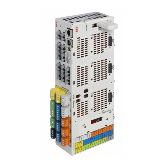
Page 11: Layout
Hardware description 11 Layout The figures show the layout of the BCU-22 control unit. For the default I/O connection diagrams and more information on the connections, see the applicable converter hardware manual. - Page 12 12 Hardware description The label describes the location of the I/O connectors and has the same Label colors as the connectors.
- Page 13 Hardware description 13 Description I/O connector Analog input Analog output Digital input and digital start interlock XDIO Digital input/output XD2D Drive-to-drive link XD24 +24 V output for digital input XPOW External power input XRO1 Relay output 1 XRO2 Relay output 2 XRO3 Relay output 3 XSTO...
-
Page 14: The 7-Segment Display
14 Hardware description Description Miscellaneous + Battery Real-time clock battery The 7-segment display The following table gives the indications of the 7-segment display on the control unit. Multi- character indications are displayed as repeated sequences of characters. “U” is indicated shortly before “o”. The control program has been launched and is running. -
Page 15: Installation
Installation 15 Installation Contents of this chapter This chapter gives information about the installation procedures and the contents of the delivery. Examining the delivery Make sure that these items are included: • control unit with the I/O connectors • memory unit •... -
Page 16: Mechanical Installation
The minimum recommended distance from such components is 200 mm (7.9 in). ABB recommends to install metallic screening between the control unit and the source of disturbance. This can reduce the required distance. -
Page 17: Installing The Control Unit
Installation 17 Installing the control unit The control unit is grounded through the DIN rail. Vertical DIN rail mounting 1. Attach the latches to the back of the control unit with four screws for each latch. 2. Push the control unit to the rail as shown below. It makes a click. 3. -
Page 18: Horizontal Din Rail Mounting
18 Installation Horizontal DIN rail mounting 1. Attach the latches to the back of the control unit with four screws for each latch. 2. Push the control unit to the rail as shown below. It makes a click. 3. (Optional) To prevent movement of the control unit, attach it to the rail with screws or end brackets. -
Page 19: Installing The Fso-Xx Safety Functions Module
Installation 19 Installing the FSO-xx safety functions module 1. Install the FSO-xx safety functions module onto slot 3 with four screws. 2. Tighten the FSO-xx electronics grounding screw. Tightening torque 0.8 N·m (7.1 lbf·in). 3. Connect the FSO-xx data cable to FSO-xx connector X110 and to BCU connector X12. -
Page 20: Electrical Installation
20 Installation Electrical installation WARNING! Obey the safety instructions given in ACS880 multidrive cabinets and modules safety instructions (3AUA0000102301 [English]), or ACS880 liquid- cooled multidrive cabinets and modules safety instructions (3AXD50000048633 [English]), or ACS880-04XT drive modules (500 to 1200 kW) hardware manual (3AXD50000025169 [English]). -
Page 21: Maintenance
Maintenance 21 Maintenance Contents of this chapter This chapter gives instructions on how to do maintenance on the control unit. Replacing the real-time clock battery Replace the real-time clock battery if the BATT OK LED is off when the control unit is powered. -
Page 22: Replacing The Memory Unit
22 Maintenance Replacing the memory unit WARNING! Do not remove or install the memory unit when the control unit is powered. See B in figure Replacement illustration (page 23). 1. Remove the screw. 2. Pull out the old memory unit. 3. -
Page 23: Replacement Illustration
Maintenance 23 Replacement illustration... - Page 24 24 Maintenance...
-
Page 25: Technical Data
Technical data 25 Technical data Contents of this chapter This chapter contains the technical data for the control units. Connector data Terminal Power supply Connector pitch 5 mm, wire size 2.5 mm (XPOW) 24 V (±10%) DC, 2 A External power input. Two supplies can be connected for redundancy. Relay outputs RO1…RO3 Connector pitch 5 mm, wire size 2.5 mm (XRO1…XRO3) - Page 26 26 Technical data Start interlock input DIIL Connector pitch 5 mm, wire size 2.5 mm (XDI:7) 24 V logic levels: “0” < 5 V, “1” > 15 V : 2.0 kohm Input type: NPN/PNP Hardware filtering: 0.04 ms, digital filtering up to 8 ms Digital inputs/outputs DIO1 Connector pitch 5 mm, wire size 2.5 mm and DIO2...
- Page 27 Technical data 27 Safe torque off output Connector pitch 5 mm, wire size 2.5 mm (XSTO OUT) To STO connector of inverter module Control panel connection Connector: RJ-45 (X13) Cable length < 3 m (10 ft) Ethernet connection Connector: RJ-45 (XETH) This connection is not supported by the firmware.
-
Page 28: Ground Isolation Diagram
28 Technical data Ground isolation diagram XPOW +24VI +24VI +VREF -VREF AGND AI1+ Common mode voltage between AI1- each AI input and AGND is AI2+ AI2- +30 V AGND AGND XD2D BGND SHIELD XRO1, XRO2, XRO3 XD24 +24VD DICOM +24VD DIOGND XDIO DIO1... -
Page 29: Other Information
ABB and its affiliates are not liable for damages and/or losses related to such security breaches, any... - Page 30 30 Technical data...
-
Page 31: Dimension Drawings
Dimension drawings 31 Dimension drawings Contents of this chapter This chapter shows the dimensions of the control unit. -
Page 32: Dimension Drawing Of The Control Unit
32 Dimension drawings Dimension drawing of the control unit... -
Page 33: Further Information
Product and service inquiries Address any inquiries about the product to your local ABB representative, quoting the type designation and serial number of the unit in question. A listing of ABB sales, support and service contacts can be found by navigating to abb.com/searchchannels. - Page 34 © Copyright 2019 ABB. All rights reserved. Specifications subject to change without notice.