
Related Manuals for ABB Baldor BC141


Summary of Contents for ABB Baldor BC141
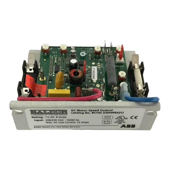
- Page 1 BC141, BC142, BC142-5 & BC142-6 DC Control Installation & Operating Manual 5/17 MN704...
- Page 2 Any trademarks used in this manual are the property of their respective owners. Important: Be sure to check www.baldor.com to download the latest version of this manual in Adobe Acrobat PDF format.
-
Page 3: Table Of Contents
Table of Contents Chapter 1 Introduction Introduction ..............1-1 Safety Notice . -
Page 4: Introduction
Chapter 1 Introduction Introduction Thank you for purchasing the BC141, BC142, BC142-5 or BC142-6 full-wave variable speed DC motor control. The control, with Surface Mount (SMT) construction, offers the user the ultimate in reliability and performance at an affordable price. The controls contain a unique patented super-fast Direct- Fed™... -
Page 5: Receiving
SAFETY NOTICE Continued WARNING: If possible, do not adjust trim pots with the main power applied. Electrical shock can cause serious or fatal injury. If adjustments are made with the main power applied, an insulated adjustment tool must be used to prevent shock hazard and safety glasses must be worn. WARNING: Do not use this drive in an explosive environment. - Page 6 Table 1-1 Electrical Ratings Rating without Auxiliary Heat Field Rating with Auxiliary Heat Sink Sink AC Line Motor Catalog Max DC Max DC (1.13 Number (±15%, Load Load AC Line AC Line Power Power Amps 50/60Hz) Current Current Current Current HP (kW) HP (kW) Max)
- Page 7 MN704...
-
Page 8: Installation
Chapter 2 Installation WARNING: Do not use this drive in an explosive environment. An explosion can cause serious or fatal injury. This drive is not explosion proof. MOUNTING INSTRUCTIONS It is recommended that the control be mounted on a flat surface with adequate ventilation. Leave enough room to allow for AC line, motor connection, and other wiring that is required. -
Page 9: Ac Line Connection
The AC Line Fuse protects the control against catastrophic failure. If the AC Line Fuse blows, the control is miswired, the motor is shorted or grounded, or the control is defective. Fuse holders and fuses not supplied with BC142-5. Note: Fuse each AC line conductor that is not at ground potential. Figure 2-2 Control Layout &... -
Page 10: Permanent Magnet (Pm) Motor Connection
Permanent Magnet (PM) Motor Connection Connect the motor armature positive lead (+) to Terminal A+ (Armature Fuse*) and the negative lead (-) to Terminal A-. On Catalog Nos. BC142, BC142-5 and BC142-6, be sure Jumper J2 is set to the corresponding motor voltage. -
Page 11: Remote Main Speed Potentiometer Connection
Table 2-4 Plug-In Horsepower Resistor® & Armature Fuse Kit Selection 90 -130 VDC 180 VDC Approximate Plug-In HP Resistor and Plug-In HP Armature Fuse Motors (HP) Motors (HP) Motor Current Armature Fuse Kit Cat. Resistor Value Rating (Amps) (ADC) (Ω) 1/100 1/50 BR1000... -
Page 12: Enable Circuit Connection
Figure 2-4 Voltage Following Connection Terminal "P2" Terminal "P1" 0 - 9 Volts DC (Isolated) Notes: 1. If an isolated signal input is not available, or if using a 4 - 20 mA DC signal input, install the optional plug-on Catalog No. BC152 Signal Isolator. This will also allow direct connections to process controllers and microprocessors. -
Page 13: Inhibit Circuit Connection
Notes: 1. The deceleration time can only be made longer than the normal coasting time of the load. 2. If the BC152, Signal Isolator option board is installed onto the BC141, or BC142 control, the ENABLE circuit will not funciton as described. If an ENABLE feature is required for the application, connect a N.O. - Page 14 Seven (7) Volt per 1000 RPM Tachometer Connect the tachometer positive lead (+) to Terminal T and the negative lead (-) to Terminal I2. Figure 2-8 DC Tachometer Connection (7 Volts Per 1000 RPM) Terminal "T" Terminal "I2" 1000 DC Tachometer Fifty (50) Volt per 1000 RPM Tachometer Connect the tachometer positive lead (+) to Terminal B and the negative lead (-) to Terminal I2.
-
Page 15: Armature Switching And Dynamic Braking
Armature Switching and Dynamic Braking If the armature is to be disconnected and reconnected with the AC power applied, connect a relay (or contactor) and a brake resistor (RB) in the armature circuit. The Inhibit Circuit must be simultaneously activated when braking. Wire a double pole double throw (DPDT) mechanically ganged switch to the Inhibit Terminals and the relay (or contactor) coil. -
Page 16: Trimpot Adjustments
Figure 2-11 Motor Voltage & DC Tachometer Selection (Jumper J2) Catalog No . BC141 Catalog Nos. BC142, BC142-5 and BC142-6 J2 Set for J2 Set for J2 Set for J2 Set for J2 Set for 90 Volt Motor 180 Volt Motor 90 Volt Motor Tachometer Tachometer... - Page 17 Note: Readjusting the MIN Trimpot will affect the maximum speed setting. Therefore, it is necessary to readjust the MAX Trimpot if readjusting the MIN Trimpot. It may be necessary to repeat these adjustments until both the minimum and maximum speeds are set to the desired levels. Maximum Speed Trimpot (MAX) The MAX Trimpot sets the maximum speed of the motor when the Main Speed Potentiometer is set fully clockwise.
-
Page 18: Operation
3. Run the motor with the maximum load and adjust the IR Trimpot so that the motor speed under load equals the unloaded speed recorded in step 2. 4. Remove the load and recheck the RPMs. 5. If the unloaded RPM has changed, repeat steps 2 - 4 for more exact regulation. The control is now compensated to provide minimal speed change due to changing loads. -
Page 19: Optional Accessories
Table 2-4 Troubleshooting Guide (without Optional Forward-Brake-Reverse Switch) Symptom Possible Cause Suggested Corrective Action Faulty wiring or loose connections Check and correct connections. to the reversing switch. Motor will not run in Forward or Reverse direction. Forward-Brake-Reverse Switch is Replace Forward-Brake-Reverse Switch defective. - Page 20 MN704-0517 Baldor Electric Company P.O. Box 2400, Fort Smith, AR 72902-2400 U.S.A., Ph: (1) 479.646.4711, Fax (1) 479.648.5792, International Fax (1) 479.648.5895 www.baldor.com © Baldor Electric Company All Rights Reserved. Printed in USA. MN704 (A40249) - Rev E 5/17...