
Related Manuals for Lumberjack BS250


Summary of Contents for Lumberjack BS250
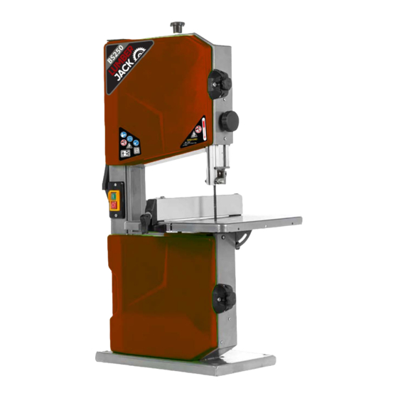
- Page 1 SAFETY AND OPERATING MANUAL 10” Bench Top Hobby Bandsaw BS250 ORIGINAL INSTRUCTIONS BS250...
-
Page 2: Table Of Contents
TABLE OF CONTENTS Welcome to Lumberjack! Dear customer, Congratu n your purchase. Before using the Product for the first me please be sure to read these instruc ons for use. They provide you with all informa necessary for using the product safely and to ensure its long service life. -
Page 3: General Power Tool Safety Warnings
Remove any adjusting key or wrench before conditions. Water entering a power tool will turning the power tool on. A wrench or a key left increase the risk of electric shock. attached to a rotating part of the power tool may result in personal injury. BS250... - Page 4 Store idle power tools out of the reach of children and do not allow persons unfamiliar with the power tool or these instructions to operate the power tool. Power tools are dangerous in the hands of untrained users. BS250...
- Page 5 7.9 Store the machine in a safe manner when not being used. The storage location must be dry and lockable. This prevents the machine from storage damage and from being operated by untrained persons. BS250...
-
Page 6: Symbols
The machine must be disconnected from the supply before maintenance! Disconnect the mains plug prior to the repair, cleaning, and maintenance of the saw! Keep children and bystanders off and away. BS250... -
Page 7: Specifica Ons
SPECIFICATION Machine Details CONTENTS SUPPLIED BS250 Model Number The bandsaw comes partially assembled and is 230-240V 50Hz, n shipped in carefully packed carton. After all the AC Motor 2982 min parts have been removed from the carton, you Power P... -
Page 8: Assembly
× NOTE: Before fastening the work table, make sure table be aligned in two planes. Laterally, in order for the blade to run dead centre through the table insert.At right angles to the blade. M6 × 35 × 1 BS250... - Page 9 ASSEMBLY Rip Fence Clamp the rip fence. It can be used on both sides of blade. Locker BS250...
-
Page 10: Features & Set Up
Upper Housing Door Setting Knob for Blade Guard ON/OFF Switch Work Table Rip Fence Lower Housing Door Door Lock Push Stick Setting Knob for Blade Tracking Adjustment Blade Setting Knob for Work Table Power Cord and Plug Suction Connector Motor BS250... - Page 11 Saw Table Lateral Alignment 1. Loosen the three fastening screws that hold the lower table trunnion. 2. Align working table so that the blade runs through the centre of the table insert’s slot. 3. Tighten the three fastening screws again. BS250...
- Page 12 Limit Stop Screw the right position. Locking Nut Setting Knob 3 mm 5. Tighten locking nut. Setting Up the Rip Fence The rip fence is clamped to the front. It can be used on both sides of the blade. BS250...
-
Page 13: Ope N & Maintenance
Machine has suction connector, The saw can be switched on by pressing the user can connect the machine to a green pushbutton. proper suction unit when working. The red pushbutton has to be pressed to switch off the machine. BS250... - Page 14 5. Fit fresh bandsaw blade. Ensure correct position: the teeth must point towards the front of the saw (where the doors are). 6. Center bandsaw blade on the rubber tyres of the band saw wheels. BS250...
- Page 15 4. Slide the lower saw wheel with big pulley off the shaft which will dislodge the belt discard the old belt. Locking Screw BACK VIEW Motor Belt Drive Pulley LOOSEN FRONT VIEW Snap Ring Wheel Shaft Snap Ring Snap R BS250...
- Page 16 3. Push the motor down to add tension to the belt. The belt is properly tensioned when moderate finger pressure on the belt between the two pulleys causes a 1.2cm deflection. 4. Tighten the screw that secures the motor. BS250...
- Page 17 - band saw blade = 0.5 mm 1. Remove table insert from saw table (push - if the band saw blade is turned by hand, it up from underneath). shall not touch the thrust bearing. 2. Fit new table insert. Table Insert BS250...
-
Page 18: Trouble Sho
1. Change the saw blade 1. Blunt saw blade Saw blade jams 2. Clean the saw blade 2. Deposits on the saw blade during cutting work 3. Set the saw blade guide according 3. Guide has been set poorly to the operating instructions BS250... -
Page 19: Lumberjack Guarantee
1.2.7 The product has not been used for 1.2.3 If asked to do so by lumberjack or hire purposes. its Authorised Dealer, you return the product at your own cost to 1.2.8 The product has been purchased by... - Page 20 2. Claims Procedure 2.4 Please note that it is essential that the letter of claim reaches Lumberjack on the last day of this 2.1 In the first instance please contact the guarantee at the latest. Late claims will not be Authorised Dealer who supplied the product to considered.
-
Page 21: On Of Conformity
Old Heat h Road, Wolverhampton, WV1 2RP. Declare that the product: Designation: 10" Bench Top Bandsaw Model: BS250 Complies with the following Directives: Electromagnetic Compatibility Directive - 2004/108/EC Machine Directive - 2006/42/EC Restrictions of the use of Hazardous Substances in Electrical Equipment - 2011-65/EU Waste Electrical and Electronic Equipment - 2012/19/EU Standards &... -
Page 22: Parts List
Cable Fixing Plate Guide Block Spring Washer 4 Plug & Power Cord Lock Washer 4 Bolt M6×20 Screw M5×10 Flat Washer 8 Screw M4×16 Bolt M6×16 Band Saw Wheel-Lower Big Flat Washer 6 Pulley-Lower Bench Angle Gauge Belt Lock Plate BS250... - Page 23 Upper Blade Guide Inserter Upper Guide Pin Subplate Fixing Rod Self-plugging Rivet 4×8 Screw M6×12 Leaf-spring Screw ST4.2×13 Knob Bolt M6×32 Upper Blade Guide Seat Fixing Seat of Door Locker Locknut Screw M5×16 U Shaped Blocker Inserter Work Table Locknut M5 BS250...
-
Page 24: Parts Diagram
PARTS DIAGRAM BS250...
Need help?
Do you have a question about the BS250 and is the answer not in the manual?
Questions and answers