Table of Contents
Advertisement
Quick Links
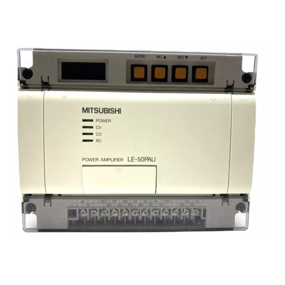
POWER AMPLIFIER
LE-50PAU
MODEL
TENSION CONTROLLER
LE-50PAU-SET
MODEL
INSTRUCTION MANUAL
This manual confers no industrial property rights or any rights of any other kind, nor does it confer
any patent licenses.
Mitsubishi Electric Corporation cannot be held responsible for any problems involving industrial
property rights which may occur as a result of using the contents noted in this manual.
Read through this manual, and use the unit correctly.
Make sure to understand " Cautions on safety " completely.
Store this manual carefully, and make sure to sent it to the end user.
© 2010 MITSUBISHI ELECTRIC CORPORATION
Advertisement
Table of Contents

Related Manuals for Mitsubishi Electric LE-50PAU


Summary of Contents for Mitsubishi Electric LE-50PAU
- Page 1 This manual confers no industrial property rights or any rights of any other kind, nor does it confer any patent licenses. Mitsubishi Electric Corporation cannot be held responsible for any problems involving industrial property rights which may occur as a result of using the contents noted in this manual.
- Page 3 Cautions on Safety (Make sure to read this page before using the unit .) To assure safety When the unit is handled incorrectly , a WA RNING : dange rous situation may occur and the • Make sure the user thoroughly read this instruction manual possibility of death or serious injury is before using the unit , and pay attention in assuring safety expected .
-
Page 5: Table Of Contents
Table of Contents CHAPTER-1 CHAPTER-2 POWER AMPLIFIRE / MANUAL POWER WINDING DIAMETER DETECTION TYPE SOURCE SEMI-AUTOMATIC TENSION ----------------------------------------------- 2 CONTROLLER -------------------------------------- 24 1. General description 1. General description Features / applications -------------------- 3 1.1 Principle of winding diameter detection- 25 General description of the unit----------- 5 1.2 Additional function of power amplifire --- 26 2. -
Page 6: Power Amplifire / Manual Power Source
LE-50PAU CHAPTER-1 POWER AMPLIFIER / MANUAL POWER SOURCE This chapter described the handling procedue of LE-5-PAU power amplifier for cases with it is used as a power amplifier itsself by using each tension control unit in combination and when it is used as a manual power source, using the valuable resistor. -
Page 7: General Description
1. General description 1.1 Features / applications The LE-50PAU power amplifier is used to control the excitation current of the excitation coil for clutch / brake such as powder clutch / brake, hysteresis clutch / brake, etc. The power amplifier is applicable mainly to the winding / unwinding tension contorl for long-size material, torque limiter for general machinery, etc. - Page 8 Main applications < Power amplifier for tension control > • The power amplifire is used in combination with the closed-loop type tension control unit such as LE-40MTA-E, LE-40MTB-E, LE-30CTN, etc. tension control unit to amplify the output signal or such control unit, and to apply the power source to the excitation coil of clutch / brake.
-
Page 9: General Description Of The Unit
1.2 General description of the unit The LE-50PAU power amplifire is a compact typeunit designed to be incorporated in the panel, using alu- minum die cast and plastic cover. MODE (11) (5)’ POWER (10) LE-50PAU POWER AMPLIFIER (1) : Mounting holes arranged at four corners of the main unit, used to fix the unit within the control panel. -
Page 10: General Description Of Function
2. General description of function 2.1 Description of operation The internal block diagram of LE-50PAU power amplifier is as shown in page 8. 1. Role of DIP switch • SW1 Keep the SW1 turned on all times under the power amplifier mode and manual power mode. - Page 11 • The amplifire A4 is used to set the output signal full-scale value (Imax), using the DIP switches SW4 ~ SW10. Note that the 24VDC voltage output mode is set when all DIP switches (SW4 ~ SW10) are turned on. Imax Vmax Vmax...
-
Page 12: Eqivalent Block Diagram
2.2 Eqivalent block diagram +10% AC100 ~ 240V 250V 8A -15% 50 / 60Hz Power source Power source Class D grounding ( 100Ω or less ) External variable resistor built-in variable Change of Powder clutch / brake resistor input signal level Hyisteresis cluthc / brake Grounding resistance 100Ω... -
Page 13: Specifications
3. Specifications 3.1 Outside dimension MODE POWER LE-50PAU POWER AMPLIFIER PULL ・ ・ ・ ・ Mounting hole (4-φ 4.5) M3.5 terminal screw • • SET SP SN ST SC PL 12V • • SN SG RS SN RC SN PN PP L... -
Page 14: Input / Output Specifications
3.2 Input / output specifications Terminal Item Specifications name • 100 to 240 VAC (-15% to +10%) , 50/60 Hz • Power fuse : 250 V, 8 A ×2, built in • Power consumption: 400 VA (at 24 VDC, 4A) •... -
Page 15: Installation / Wiring
( φ4.5 ) prepared at four corners. The LE-50PAU power amplifier is provided with a groove at the bottom • surface to avoid the DIN rail, however, it is unable to fit the LE-50PAU power amplifire to the DIN rail. 4-M4 screw CAUTION •... -
Page 16: Connection Of Power Circuit
Note that connecting the power wire to the input / output terminal or DC power terminal may cause the equipment to be broken . • Turn ON / OFF the power source of the LE-50PAU power amplifire together with that of tension controller. Use a power wire of over 2mm... -
Page 17: Connection Of Input Circuit
100Ω or less (2) LE-30CTN, LE-40MTA, LE-40MTB, LD-FX • Connect the LE-50PAU power amplifire to the LE-30CTN, LE-40MTA, LE-40MTB or LD-FX ten- sion controller as shown below in the following drawing, turn on the DIP switch SW2 and SW3, and set the input to 0 to 5V. -
Page 18: Connection Of Output Circuit
The one-reel controller or feeld roll controller does not use any aux.power amplifire. Set the DIP switch SW4 to SW10 in accordance with the rated current of clutch / brake connected to the LE-50PAU power amplifire output [PP] - [PN]. ( See page 5. ) Type LE-30CTN, LE-40MTA, LE-40MTB tension controller... -
Page 19: Initial Setting
The adjustment is executable at any time, and it is validated when the DIP SW1 is turned on, SW2 is turned off, SW3 is turned on and the power source is closed. Power Output When the power source of LE-50PAU is closed, the output cur- • display rent or output voltage is displayed soon in accordance with the sequence shown on page 23. -
Page 20: Non-Linear Compensation
5.2 Non-linear compensation 1. Non-linear characteristic The exitation current vs. transmission torque character- • 100%=Torque ata rated current istic of clutch / brake is of non-linear characteristic as shown at right, and may be different, depending on the type name of each clutch / brake. Set the transmission torque value at 10%, 20%, 40% and 80% current for non-lineare data. -
Page 21: Initial Inspection / Fault Inspection
6. Maintenance / inspection 6.1 Initial inspection / Fault inspection 1. Initial inspection Check that the applied load ( 24VDC, 4A or less ) is proper prior to closing the power source. • The mal-connection of power terminal, contact failure between DC input / output terminal and power •... -
Page 22: Maintenance Inspection
Since the standard replacement period may vary, depending upon the magnitude of output current, ambinient temperature or operation rate, place an order or smoothing capacitor from the Service Cen- ter of Mitsubishi Electric as required. The EEPROM ( used for storage of setting data ) is serviceable for 100,000 re-writing, and the power •... -
Page 23: Supplementary Items
7. Supplementary items 7.1 Special setting operation It is possible to execute the following special settings by turning on the power source with [MODE] key pressed. This special setting mode is reset when the power source is turnin on without the [MODE] key pressed. 1. - Page 24 3. Stop gain / stop bias When the [INC ] key is pressed with the [MODE] key MODE MODE Special display pressed, the gain / bias setting mode is turn on. When the same oeration is performed again , the mode is reset and the special display mode is resumed.
-
Page 25: Clutch / Brake Characteristics
7.2 Clutch / brake characteristics 1. Powdre clutch Powder clutch Transmission torque (%) Rated 100% torque Type name current (A) (N•m) 0.88 ZKG-10AN 11.0 20AN ZKG-50AN 10.4 Self-cooling ZKG-100AN 13.5 13.3 ZKB-0.06AN ZKB-0.3AN ZKB-0.6AN ZKB-1.2BN ZKB-2.5BN ZKB-5BN 10.3 Self-cooling (Air-cooling) ZKB-10BN ZKB-20BN ZKB-40BN... - Page 26 3 Powdre brake Powder clutch Transmission torque (%) Rated 100% torque Type name current (A) (N•m) Self-cooling 11.0 ZKG-10YN 10.8 15.4 20YN ZKG-50YN 18.2 Self-cooling ZKB-0.06YN ZKB-0.3YN ZKB-0.6YN ZKB-1.2XN ZKB-2.5XN ZKB-5XN 10.3 Self-cooling (Air-cooling) ZKB-10XN ZKB-20XN ZKB-40XN ZKB-2.5HBN ZKB-5HBN 10.3 Thermo-block ZKB-10HBN ZKB-20HBN...
-
Page 27: Manual Power Source With No
SW2, SW3 are turned off, the power am- SW.2=OFF plifire is set to buit-in variable resistor mode. SW.3=OFF built-in variable resistor LE-50PAU 2. Built-in variable resistor adjustment procedure DIP SW.1=ON Power on SW.2、3=OFF The setting value ( 0 to 100% ) of built-in variable resistor is dis- •... -
Page 28: Winding Diameter Detection Type Semi-Automatic Tension Controller
This chapter describes the function of such additional function and operation procedure for LE-5AP operator panel. Since the function of the LE-50PAU power amplifier is utilized as it is, be sure to refer to the description given in chapter-1 at the same time. -
Page 29: General Description
1. General description 1.1 Principle of winding diameter detection The LE-50PAU-SET tension conntroller can use either one of the following two types of winding diameter detection methods selectively. 1. Speed / thickness setting method ( sensor-less method ) • The winding diameter D(mm) for case when winding / unwinding the material ( thickness:Tµm ) at line speed of V(m/min) is given by the following formula;... -
Page 30: Additional Function Of Power Amplifire
OFF Semi-automatic tension control (See chapter-2) 2. Handling of input terminal Proximity switch (1) PL terminal -------Winding reel pulse input LE-50PAU • For pulse / thickness setting method, connect the proximity switch to the terminal. 2.2kΩ Use the voltage output type proximity switch having... -
Page 31: General Description Of Function
2. Tension setting function (1) Internal adjustment • When the built-in variable resistor ( adjustable by software ) is val- LE-50PAU idated by the LE-5AP operator panel, it is possible to adjust the input, using operator panel ina substitute for extrenal variable re- sistor. -
Page 32: Eqivalent Block Diagram
2.2 Eqivalent block diagram +10% AC100 ~ 240V 250V 8A -15% 50 / 60Hz Power source Power source Class D grounding ( 100Ω or less ) Calculation of winding diameter External variable resistor Compensation of winding diameter built-in variable Change of Powder clutch / brake resistor input signal level... -
Page 33: Operator Panel
1.0 ~ 99.0% *3 80% torque 1.0 ~ 99.0% *3 These set data is memorized in the EEPROM memory in the LE-50PAU power amplifire. *1 The set input signal level 8V is assumed 100%. *2 The output ins assumed 100% befor stopping. -
Page 34: Installation And Outline / Specification
The LE-5AP operator panel is in- stalled in the panel surface of the control console. LE-50PAU in the control console is connected and draws out the cable with an attached cable of LE-5AP through the hook as shown in a right picture. -
Page 35: Practical Operation
Note that only T1 (=100%) is acceptable to winding, and T4 (=100%) to unwinding. For other than D1<D2<D3<D4 (excluding D2, D3=0), the error is displayed when it is detected during error check. Such data is written in EEPROM memory built in LE-50PAU each time when the [ 実行 ] key is pressed. •... -
Page 36: Speed / Thickness Setting
4.2 Speed / thickness setting Similarly to description given on last page, [ 速度 / 厚さ ] key is acceptable from any screen condition on the screen displayed prior to power failure after turning on the power source. T H K T... -
Page 37: Tension / Torque Setting
4.3 Tension / torque setting Similarly to description given on page 31, [ 張力 / トルク ] key is acceptable from any screen condition on the screen displayed prior to power failure after turning on the power source. When the [ 張力 / トルク ] key is pressed, the •... -
Page 38: Error Check
( winding : D1, unwinding : D4 ). [2] If the RC input has been turned off, on control output will be sent out. If the logic is inverted at the LE-50PAU side, however, the RC input is turned on and the output is turned off. -
Page 39: Supplementary Items
5. Supplementary items 5.1 Panel design example (external variable resistor ) The following showns a design example of operation panel surface and a connection example relevant input by using the external variable resistor. Start Stop 速 度 張 力 クリア Reset 最... -
Page 40: Panel Design Example (Built-In Variable Resistor )
5.2 Panel design example (built-in variable resistor ) The following shows a design example of operation panel surface and a connection example relevant input by using the built-in variable resistor. The built-in variable resistor used is a • software type variable resistor, using the LE-5AP operator panel. -
Page 41: Setting Of Basic Function
It is possible to readily set the data, using the LE-5AP in substitute for numeric value settng, using 4 keys arranged on the LE-50PAU. In addition, it is also possible to set the maximum taper ratio for winding. (See next page.) -
Page 42: Supplementary Description
It is possible to change the terminals S1-S2 ( aux. power output ) of the LE-50PAU from the aux. power output mode to the [ RUN ] output mode by performing the following operations. [ RUN ] output means that 12VDC ( load current : 100mA or less ) is output while the LE-50PAU is op- erating properly. - Page 43 < Operation example of unwinding control > Manual Automatic operation operation [ST] Automatic Manual Automatic operation signal operation operation Stop Stop Stop gain / stop bias : validated Stop timer Initial diameter reset [RS] signal [SP] signal Winding diameter [PP]-[PN] output *1 : When the mode is changed to manual mode while two variable resistors ( AUTO / MANUAL ) are used during automatic operation under external variable resistor mode, the PP-PN output appears to be the output corresponding to the manual variable resistor.
- Page 44 MEMO...
- Page 46 POWER AMPLIFIER LE-50PAU MODEL TENSION CONTROLLER LE-50PAU-SET MODEL HEAD OFFICE: TOKYO BUILDING, 2-7-3 MARUNOUCHI, CHIYODA-KU, TOKYO 100-8310, JAPAN Effective April 2015 Specifications are subject to change without notice. JZ990D41601D...