
Related Manuals for ABB 3AUA0000235813


Summary of Contents for ABB 3AUA0000235813
- Page 1 A B B M OT I O N D R I V E S U S - C O N N EC T I V I T Y VFD-GATEWAY EtherNet/IP™ to Modbus RTU gateway User Manual Type number: VFD-GATEWAY Part number: 3AUA0000235813...
-
Page 2: Table Of Contents
— VFD-GATEWAY EtherNet/IP™ User Manual Table of contents 1. Safety Instructions 2. Installation 3. Setup 4. Troubleshooting 5. Appendix LVD-EOMU02U-EN REVD 11/2022... - Page 3 3.3 Setup, data mapping and typical parameters ACS380, ACH/Q/S580 3.4 Setup, data mapping and typical parameters ACS880 and DCS880 3.5 Setup, data mapping and typical parameters ACH580 E-Clipse 3.6 ABB drives control profile Ethernet configuration settings 15-19 3.8 Ethernet/IP scanner setup 20-22 3.9 Configuring the VFD-GATEWAY Web browser interface...
-
Page 4: Safety Instructions
— 1. Safety instructions These instructions are for all who install or connect an optional module to a drive, converter or inverter and need to open its front cover or door to do the work. WARNING! Obey these instructions. If you ignore them, injury or death, or damage to the equipment can occur. -
Page 5: Installation
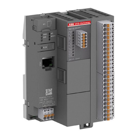
— 2. Installation Contents of this chapter This chapter describes the installation and wiring of the VFD-GATEWAY, showing how to mount the device and where the power/communications connections are made. 2.1 Mounting the VFD-GATEWAY DIN rail according to DIN EN 50022 35 mm, depth 7.5 mm or 15 mm: Mounting with screws M3 (see Appendix for hole fixing dimensions): Note: TA543 option (not included) is ordered separately from the VFD-GATEWAY. - Page 6 The following Power supply will mount on the same DIN Rail as the gateway and provide the required 340mA: ABB 1SVR427041R0000, CP-D 24/0.42 If additional power or other features are needed, additional ABB Power Supplies are available at new.abb.com/low-voltage/products/power-supplies CAUTION!
- Page 7 (This VFD-GATEWAY has built in Bus Termination and Pull Up/Pull down resistors When yellow lights are lit. bus termination resistor is activated or the pull up/pull down resistors are activated) The Modbus-RTU can be connected to up to 5 ABB drives via the following connections: VFD Gateway...
- Page 8 Press the tab on the side of the module and pull up on the module to remove it from the VFD-GATEWAY: After it is removed, turn the top dip-switches off. They are currently in the on position from the factory. Flip the switches to the left for OFF (towards the ABB logo) and reinstall. LVD-EOMU02U-EN REVD 11/2022...
- Page 9 Use shielded twisted-pair cable with a twisted pair for data and a wire or another pair for signal ground (nominal impedance 100 to 165 ohm, for example Belden 9842) for the wiring. For best immunity, ABB recommends high quality cable. Keep the cable as short as possible.
-
Page 10: Setup
— 3. Setup Contents of this chapter This chapter describes the how to configure the VFD-GATEWAY and drive parameter tables using the VFD-Gateway’s built in web browser configuration pages. 3.1 Drive Setup The VFD-GATEWAY supports the following drives and data connection sizes: Drive Supported data words ACS355... - Page 11 3.3 Setup, data mapping and typical parameters for ACS380, ACH/Q/S580 Drive Parameter Example for ACS380, ACQ/S580 Setup parameters 20.01 Start/Stop EXT 1 Embedded fieldbus 22.11 Vector Speed Ref EFB ref1 28.11 Scalar Speed Ref EFB ref1 58.01 Comms Protocol Modbus RTU*** 58.03 Node Address Drive 1,2..up to 5 * 58.04 Baud Rate...
- Page 12 3.4 Setup, data mapping and typical parameters for ACS880, DCS880 Drive Parameter Example for ACS880, DCS880 Setup parameters 20.01 Start/Stop EXT 1 Embedded fieldbus 22.11 Vector Speed Ref EFB ref1 28.11 Scalar Speed Ref EFB ref1 58.01 Comms Protocol Modbus RTU*** 58.03 Node Address Drive 1,2..up to 5 * 58.04 Baud Rate...
- Page 13 3.5 Setup, data mapping and typical parameters for ACH580 and ACH580 E-Clipse bypass ACH580 ACH580 E-Clipse Drive Parameter Example for ACH580 Drive Parameter ACH580 E-Clipse Setup parameters Setup parameters 20.01 Start/Stop EXT 1 Embedded fieldbus 16.01 Start/Stop Comm (bypass parameter) 22.11 Vector Speed Ref EFB ref1 20.01 Start/Stop EXT 1...
- Page 14 3.6 ABB Drives control profile The VFD-GATEWAY only uses the ABB Drives profile, see below for Control/Status Word and speed scaling instructions: ABB Drives profile Control Word Bit structure Byte Bit 7 Bit 6 Bit 5 Bit 4 Bit 3...
- Page 15 3.7 Ethernet configuration settings Assembly Instance Size Input 16-bit Output 16-bit Configuration 8-bit Communication mapping in the PLC/Controller: Integer Drives Input/Output data array mapping is as follows: Drive 1 = Integers 0-14 Drive 2 = Integer 15-29 Drive 3 = Integer 30-44 Drive 4 = Integer 45-59 Drive 5 = Integer 60-74 3.8 Ethernet/IP scanner setup...
- Page 16 Step 3: Set up using the Generic Ethernet Module Skip to Step 5 if using EDS file) Search for generic module and select Generic Ethernet Module and hit create. Note: Use either EDS File or Generic module DO NOT USE BOTH Step 4 : Next populate the required generic module fields per below and press OK.
- Page 17 Step 5: Using the EDS file Search for ABB VFD-GATEWAY and select create. EDS file will need to be installed into the PLC software, to be se- lected. (Note: the EDS file MUST be installed through EDS hardware installation tool before it is available to use.) Note: Use either EDS File or Generic module DO NOT USE BOTH Step 6 : On the next screen, give the module a name and enter the VFD-GATEWAY’s IP address.
- Page 18 Step 7: Select ‘Change’ under module definition. Step 8 : After change is selected the following screen will appear. Select INT and press OK. This will create 75 integers in/out. Drives Input/Output data array mapping is as follows: Drive 1 = Integers 0-14 Drive 2 = Integer 15-29 Drive 3 = Integer 30-44 Drive 4 = Integer 45-59...
- Page 19 The data registers that are not used will be just blank data as a place holder. LVD-EOMU02U-EN REVD 11/2022...
- Page 20 3.9 Configuring the VFD-GATEWAY Web browser interface This chapter describes the how to configure the VFD-GATEWAY using the VFD-Gateway’s’ built in web browser configuration pages. Step 1: Connect and power up: Connect your Ethernet cable, Modbus wiring and apply 24VDC power. From the web interface device (Laptop/PC) open a web browser window* and navigate to the default IP address 192.168.0.10 (255.255.255.0)** The VFD-GATEWAY will navigate to the main page of the setup interface.
- Page 21 Step 4: Login as Admin From the Settings screen log in by pressing the Login Button (All Caps Username: ADMIN; Default Password: ADMIN) Step 5: Update settings Once logged in as the Admin user the following settings can be updated: •...
- Page 22 Step 6: Apply changes Apply changes by (1) checking the ‘Ready to apply’ button/check box, then (2) Apply setting button: The VFD-GATEWAY will perform a restart (communication will be lost) and the web interface will need to be reconnected with the new IP address. Note: Confirm the updated settings have been updated by navigating back to the settings screen.
- Page 23 3.10 Additional screens and settings Changing the VFD-GATEWAY ADMIN password Step 1: From the settings Screen Login as the ADMIN user Step 2: Enter Username: ADMIN; Default Password: ADMIN) click OK. Step 3: Click Change Password. Step 4: The password change box will prompt you to enter the existing password and the new password twice. LVD-EOMU02U-EN REVD 11/2022...
- Page 24 Modbus RTU configuration Modbus RTU settings can be found on the Setting screen. Note: The Modbus RTU settings can’t be changed. The Settings screen shows the Active Ethernet/IP settings and the Active Modbus Settings. Note: The Standard User can only view the settings from this page. LVD-EOMU02U-EN REVD 11/2022...
- Page 25 VFD-GATEWAY data tables The VFD-GATEWAY Drive data tables (Drive 1 shown) will display data read and write data within the VFD-GATEWAY and can be used for troubleshooting. The Modbus Node Selected in the Settings Screen will be shown above the Data table. The Actual Gateway Drive Data being transferred from the VFD to the Ether-net/IP Network (Read Data) and the Ethernet/IP network to VFD (Write Data) is displayed in the tables.
- Page 26 Alarms The Alarm screen shows any Communication errors on each of the Ethernet/IP or Modbus Drive Nodes. The VFD-Gateway Alarms can be represented in the following Output Lights. The wiring shown is optional, each output has a status LED built into the VFD-GATEWAY. LVD-EOMU02U-EN REVD 11/2022...
- Page 27 The VFD-Gateway Alarms can be accessed by the Scanner PLC through the Ethernet/IP network. Drives Input/Output data array mapping is as follows: • Drive 1 = Integers 0-14 • Drive 2 = Integer 15-29 • Drive 3 = Integer 30-44 •...
-
Page 28: Troubleshooting
— 4. Troubleshooting Contents of this chapter This chapter describes typical errors and conditions that may prevent operation. 4.1 Hard reset of the VFD-GATEWAY In cases where you need to reset the VFD-GATEWAY to factory settings, it can be achieved with the hard reset procedure: 1. - Page 29 • Check Start Stop Speed Reference (refer to drive set up page) for all drives • Make sure the control device is sending the correct information see ABB State Machine (refer to state machine area of the drive manual) •...
-
Page 30: Appendix
— 5. Appendix Contents of this chapter This chapter contains dimensions, technical information and resources for the of the VFD-GATEWAY. 5.1 Dimensions VFD-GATEWAY in (mm) in (mm) in (mm) in (mm) in (mm) in (mm) in (mm) in(mm) in (mm) in (mm) 5.63 3.23... - Page 31 5.3 Module Status LEDs State Color LED=ON LED=OFF LED Flashing Power supply Green Power supply Power supply present missing Micro memory Yellow Micro memory Micro memory Micro memory card indication card is in the card is not in the card is in read/ socket socket write state...
- Page 32 ABB does not accept any responsibility whatsoever contents – in whole or in parts – is forbidden without prior for potential errors or possible lack of information in this written consent of ABB.