
Related Manuals for ABB DG/S 1.1


Summary of Contents for ABB DG/S 1.1
- Page 1 ® Product Manual ABB i-bus EIB / KNX DALI-Gateway DG/S 1.1 Intelligent Installation Systems...
- Page 2 This manual describes the function of the 1-fold DALI-Gateway with its application “Dim Light Scenes Dynamic 1f/1” programs Subject to changes and errors excepted. Exclusion of liability: Despite checking that the contents of this document match the hardware and software, deviations cannot be completely excluded. We therefore cannot accept any liability for this.
-
Page 3: Table Of Contents
1.3.1 DALI-Gateway DG/S 1.1 ..............6 1.3.2 DALI-Gateway DG/S 8.1 ..............8 Device technology Technical data for DG/S 1.1 ...............10 Circuit diagram for DG/S 1.1...............12 Dimension drawing for DG/S 1.1 ............12 Assembly and installation ..............13 Commissioning ...................14 Assignment of the physical EIB / KNX address........14 Display elements ................14... - Page 4 Meaning of the symbols ..............90 A.1.6 Configuration mode................91 A.1.7 Exiting the DGS11 Software Tool ............94 A.1.8 Automatic addressing via DG/S 1.1 ..........94 A.1.9 Exchange of DALI equipment ............95 Scope of delivery ................96 DALI equipment ..................96 DALI assignment table................97 Feedback status behaviour..............98 Code table for 8-bit scene telegram ...........99...
-
Page 5: General
ABB i-bus® 1-fold EIB / DALI-Gateway including installation and para- meterisation and explains the use of the gateway using examples. With the ABB i-bus® ® DALI-Gateway DG/S 1.1, it is possible to integrate devices with DALI (DALI = Digital Addressable Lighting Interface) interfaces into EIB / KNX intelligent installation systems and to fully utilise the functions of the DALI standard across large areas. -
Page 6: Product And Functional Overview
EIB / KNX. The DALI addresses are allocated individually and automatically by the DG/S 1.1. A change of the DALI addresses is possible if required with the separate DGS11 Software Tool, even without ETS. The 64 DALI devices connected to the main channel A can be directly switched, dimmed or controlled with a brightness value using just one EIB / KNX communication object. -
Page 7: General Dali Information
The control cable does not require any SELV characteristics (safety extra-low voltage). The two superfluous cores of the five-core NYM 5x1.5 mm mains cable can thus be used for example as a DALI cable. © 2006 ABB STOTZ-KONTAKT GmbH... - Page 8 DALI control cable. The internal DALI devices have different individual DALI addresses and can be addressed individually via DALI. The DALI-Gateway DG/S 1.1 recognises every individual DALI device in the DALI equipment. Each DALI device can be monitored and controlled individually.
-
Page 9: Dali Functional Description
“Lighting equipment”). It is possible to control fluorescent lamps, incandescent lamps, LEDs etc. via DALI, combine them into lightscenes and to integrate them with the ABB i-bus® DALI-Gateway DG/S 8.1 and DG/S 1.1 in the EIB / KNX building installation. -
Page 10: Abb I-Bus® Dali-Gateways Dg/S
EIB / KNX ABB i-bus® DALI- Gateways DG/S ABB STOTZ KONTAKT GmbH has two EIB/DALI-Gateways in the ABB i- bus® range, in order to integrate equipment with DALI interfaces into an EIB / KNX building installation. Every gateway has its advantages which benefit different project types. - Page 11 ABB i-bus EIB / KNX The 1-fold DALI-Gateway DG/S 1.1 can of course be used for every other project. This can be necessary for example where the highest level of flexibility or individual status information for every individual device is required.
-
Page 12: Dali-Gateway Dg/S 8.1
The detailed function of the 8-fold DALI-Gateway will not be dealt with in this manual. Refer to the product manual “DALI- Gateway DG/S 8.1” which can be downloaded from the homepage of ABB Stotz Kontakt (www.abb.de/eib). The following diagram illustrates the channel-based function of the 8-fold DALI-Gateway DG/S 8.1. - Page 13 ® DG/S 1.1, DALI-Gateway ABB i-bus EIB / KNX Fig. 3 DALI-Gateway DG/S 8.1, Operating principle © 2006 ABB STOTZ-KONTAKT GmbH...
-
Page 14: Device Technology
The 1-fold EIB/DALI-Gateway DG/S 1.1 is a modular installation device in proM design for installation in the distribution board on 35 mm mounting rails. The connection to the ABB i-bus® EIB / KNX is implemented via bus connecting terminals. The DALI-Gateway can integrate devices with a DALI interface into an EIB / KNX building installation using the application program "Dim Lightscenes Dynamic 1f/x". - Page 15 The programming requires EIB Software Tool ETS2 V1.3 or higher. If ETS3 is used, a “.VD3” type file must be imported. The user program is located in ETS2 / ETS3 under ABB/Beleuchtung/ DALI/ Dim Lightscenes Dynamic 1f/1. © 2006 ABB STOTZ-KONTAKT GmbH...
-
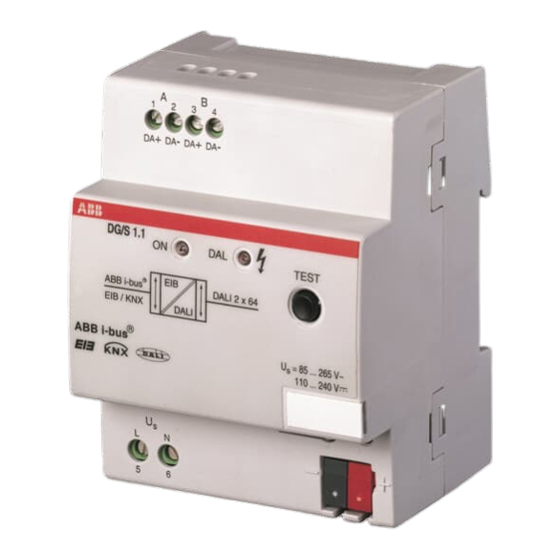
Page 16: Circuit Diagram For Dg/S 1.1
EIB / KNX Circuit diagram for DG/S 1.1 2CDC 072…F0005 Fig. 4: Circuit diagram of the 1-fold DALI-Gateway DG/S 1.1 1 Label carrier 6 Green operating LED 2 EIB / KNX programming button 7 Operating voltage 3 EIB / KNX red programming LED... -
Page 17: Assembly And Installation
EIB / KNX Assembly and installation The DALI-Gateway DG/S 1.1 is suitable for installation in distribution boards or small enclosures for rapid installation on 35 mm mounting rails to DIN EN 60 715. The mounting position can be selected as required. -
Page 18: Commissioning
EIB / KNX address The assignment of the physical EIB / KNX address of the DALI-Gateway DG/S 1.1 is carried out via the ETS and the programming button on the device. The DALI-Gateway DG/S 1.1 has a programming button for assigning the EIB / KNX physical address which is located on the collar of the device. -
Page 19: Manual Operation
The user program Dim Lightscenes Dynamic 1f/1 is pre-installed. 2.10 Maintenance and cleaning The DG/S 1.1 DALI-Gateway is maintenance free. No repairs should be carried out by unauthorised personnel if damage occurs (e.g. during transport or storage). The warranty expires if the device is opened. -
Page 20: Commissioning
DALI knowledge via the EIB / KNX or by using the DGS11 Software Tool specially developed for the DG/S 1.1. As soon as the 1-fold DALI-Gateway DG/S 1.1 is connected to the operating voltage, the DG/S 1.1 independently checks the DALI devices on both channels. -
Page 21: Dali Assignment With Separate Dgs11 Software Tool
DALI assignment with separate DGS11 Software Tool The use of a specially developed DGS11 Software Tool for the DG/S 1.1 is the most comfortable and convenient way to test and individually readdress the DALI devices connected to the gateway. The DGS11 Software Tool operates exclusively with the 1-fold DALI- Gateway DG/S 1.1 and does not require ETS. -
Page 22: Eib / Knx Commissioning
Overview The user program Dim Lightscenes Dynamic 1f/1 must be used for the 1-fold DALI-Gateway DG/S 1.1. Programming is implemented with ETS2 V 1.3 or higher. If ETS3 is used, a “.VD3” type file must be imported. -
Page 23: General" Parameter Window
“General” parameter window In the “General” parameter window the basic settings of the 1-fold DALI- Gateway DG/S 1.1 can be made which affect the gateway with both outputs/channels and all connected DALI devices. Reaction on DALI or EIB bus voltage failure... - Page 24 With this parameter, you determine how the connected DALI devices react when the EIB / KNX power supply or DALI control voltage (DG/S 1.1 operating voltage) recovers. In addition to the “no change” and “Off” states, the “max. brightness value” and “min. brightness value” are available.
- Page 25 After the burn-in time has elapsed or the function is deactivated (telegram value of the communication object "Lamp burn-in" equal to "0"), the channel can be dimmed and programmed lightscenes can be accessed. © 2006 ABB STOTZ-KONTAKT GmbH...
- Page 26 The information about the burn-in time which has elapsed up to now is lost after a download or after a failure of the AC/DC operating voltage on the DG/S. The burn-in time is deactivated. © 2006 ABB STOTZ-KONTAKT GmbH...
-
Page 27: Devices Channel A" Parameter Window
(time between two telegrams) can be considered in the "General" parameter page. This limitation refers to the individual status messages of the switching state and the brightness values. The parameterised time applies for all DALI devices. © 2006 ABB STOTZ-KONTAKT GmbH... -
Page 28: Normal" Operating Mode
(Broadcast commands). The minimum physical brightness of DALI equipment is the brightness level which the luminaire can set as the minimum dimming value conditioned by its physical properties. Typical values for the minimum physical brightness of ballasts are 1...10%. © 2006 ABB STOTZ-KONTAKT GmbH... - Page 29 Switching off is not possible. This function is not supported by DALI. It is possible to dim down to the minimum brightness value. The device must be switched off via the shutoff command (e.g. short push of a button). © 2006 ABB STOTZ-KONTAKT GmbH...
- Page 30 This is due to the fact that dimming steps are defined in the standard in order to achieve a logarithmic dimming curve which appears as a linear response to the human eye. © 2006 ABB STOTZ-KONTAKT GmbH...
- Page 31 (the time delay can be over 90 seconds). The option “always” means that a status message of the current state is sent each time a telegram is received. It is possible that delayed status messages can occur in this case. © 2006 ABB STOTZ-KONTAKT GmbH...
-
Page 32: Dynamic" Operating Mode
To help in understanding this concept, the parameterisation of a staircase lighting function with several devices is described as an example in chapter The start of dynamic operation is implemented via a telegram with the value “1”. A telegram value of “0” has no effect. © 2006 ABB STOTZ-KONTAKT GmbH... - Page 33 00. Device 64 has the DALI address 63. The offset has been taken into consideration in complete application programs with all parameters and objects as well as in the DGS11 Software Tool. The user only needs to use device numbers from 1 to 64. © 2006 ABB STOTZ-KONTAKT GmbH...
- Page 34 “Selected Device On/Off” (the device must be selected beforehand), but rather calls up the corresponding scene values, i.e. if the DG/S 1.1 receives a telegram with the value “1”, the parameterised start scene and subsequently the parameterised end scene in the “Dynamic”...
- Page 35 (the time delay can extend for 90 seconds). The option “always” means that a status message of the current state is sent each time a telegram is received. It is possible that delayed status messages can occur in this case. © 2006 ABB STOTZ-KONTAKT GmbH...
-
Page 36: Slave" Operation Mode
“1” telegram via the object Channel x “Channel slave mode on/off”. The slave mode can be deactivated for individual devices without influencing the state of the slave mode of other devices via the individual objects Channel x “Selected Device Slave Mode”. © 2006 ABB STOTZ-KONTAKT GmbH... -
Page 37: Devices Channel B" Parameter Window
In this parameter window, the properties of every individual DALI device of auxiliary channel B are set. The parameters have the same functions as those described for channel A in the section “Device channel A parameter window”. © 2006 ABB STOTZ-KONTAKT GmbH... -
Page 38: Central Function A&B" Parameter Window
Channel x “On/Off” (x = 1, 2) only have to control the function of the dynamic operation, i.e. if the DG/S 1.1 receives a telegram with the value “1”, the parameterised start scene and subsequently the parameterised end scene in the “Dynamic”... - Page 39 OFF value. This dimming time only affects dimming commands which are received via ON/OFF telegrams. A soft start or soft stop can be set with this parameter. With the setting “constant dimming speed”, the same speed © 2006 ABB STOTZ-KONTAKT GmbH...
- Page 40 0 % (off) or 100%. The setting “individual device adjustment” has the effect that the parameterisation of the individual sample is still valid for this DALI sample, if a central control received. © 2006 ABB STOTZ-KONTAKT GmbH...
-
Page 41: Dynamic" Parameter Window
A cut-out warning (to DIN 18015) can be implemented with the end scene. Fig. 12 Graphic representation of dynamic operation A telegram with the value “1” starts the dynamic process of the transmitting device. A telegram with the value “0” has no effect. © 2006 ABB STOTZ-KONTAKT GmbH... - Page 42 A very convenient warning time can be programmed at the end of the staircase lighting time with the end scene transition time (second scene) and the run time of the end scene. © 2006 ABB STOTZ-KONTAKT GmbH...
-
Page 43: Scenes" Parameter Window
Retrieve scene 15 128 or 192 Store scene 1 129 or 193 Store scene 2 130 or 184 Store scene 3 … … 191 or 206 Store scene 15 Table 6 Retrieve / store scenes © 2006 ABB STOTZ-KONTAKT GmbH... - Page 44 ETS download after an EIB recovery. Channel Number Option: With this parameter, the channel is selected to which the device to be parameterised is connected. This parameter is visible if the parameter “overwrite the scene on download” set with “yes”. © 2006 ABB STOTZ-KONTAKT GmbH...
- Page 45 (refer to the “Device” parameter window), this value is stored in the scene but the minimum or maximum brightness value of the corresponding DALI device is set automatically if the scene is retrieved. © 2006 ABB STOTZ-KONTAKT GmbH...
- Page 46 If the lightscene transition, e.g. for device A1 is changed, it is also changed for the following parameter windows of the device xy (x = A, B, y = 1….64). © 2006 ABB STOTZ-KONTAKT GmbH...
-
Page 47: Status" Parameter Window
With the setting "only on read request", the object value "Telegr. fault ballast" can only be read when requested. For the parameter setting "on change of status", the current status is sent independently via the communication object when changed. © 2006 ABB STOTZ-KONTAKT GmbH... - Page 48 If the DALI-Gateway does not receive a telegram within a defined time interval, the fault on the EIB communication channel or a device fault is assumed and a response defined in the General parameter © 2006 ABB STOTZ-KONTAKT GmbH...
- Page 49 The behaviour during a fault if no telegram with the value “1” is received by object no. 250 “Telegr. communication received” within the parameterised time, must be set in the “General” parameter window. © 2006 ABB STOTZ-KONTAKT GmbH...
-
Page 50: Communication Objects
B “Select Device” beforehand. This means that the function of channel B can only be used with the corresponding logic. The logic must first of all select the device before the function can be implemented. © 2006 ABB STOTZ-KONTAKT GmbH... - Page 51 Fig. 15 Block diagram – Select Device The selected device remains selected after a download or failure and recovery of the operating voltage. No device is selected after an EIB / KNX bus voltage recovery. © 2006 ABB STOTZ-KONTAKT GmbH...
-
Page 52: Communication Objects For The Entire Channel
DALI devices connected to it. It is a central function (broadcast mode) which relates to all devices of the channel. This function is comparable with the method of function of the ABB i-bus® EIB / KNX 8-fold DALI-Gateway DG/S 8.1. - Page 53 (Status parameter window), a lamp fault (e.g. failure) which is caused by one or more ballasts of the channel, is sent or read out (e.g. for maintenance purposes). Telegram value “1”: Fault of one or more lamps on the channel "0": No fault © 2006 ABB STOTZ-KONTAKT GmbH...
- Page 54 Ballasts” can be manually triggered if the test button on the DALI device is pressed for longer than 5 seconds. Table 7 Communication objects for "Channel X" For the DALI output (channel) B, the corresponding communication objects 18 to 24 apply. © 2006 ABB STOTZ-KONTAKT GmbH...
-
Page 55: Communication Objects For Every Dali Device
Switch ON values which are greater than or less than the max. or min. values will not be set, but rather the parameterised max. or min. value. Parameters can be used to set whether the brightness value is dimmed or immediately applied. © 2006 ABB STOTZ-KONTAKT GmbH... - Page 56 The slave mode is deactivated after a download, mains voltage failure or EIB / KNX bus voltage recovery. Telegram value "1": Switch on slave mode "0": Switch off slave mode Note: The slave mode for all devices of channel X can be activated with the channel object “Devices Slave Operation On/Off”. © 2006 ABB STOTZ-KONTAKT GmbH...
- Page 57 DALI device selected beforehand with the “Select Device” object (no. 7) is transmitted or read via this object (e.g. for maintenance purposes), depending on the parameter setting (Status parameter window). Telegram value “1”: Fault of one or more lamps on the channel "0": No fault © 2006 ABB STOTZ-KONTAKT GmbH...
- Page 58 5 seconds. Free unused Channel A or & Channel B Table 8 Communication objects for "Channel X" For auxiliary channel B (DALI output), the corresponding communication objects 25 to 35 apply. © 2006 ABB STOTZ-KONTAKT GmbH...
-
Page 59: Lightscene Communication Objects
Scenes parameter window. The scene can consist of devices from channel A and B. Telegram value “0”: Recall scene X "1": Recall scene Y Table 9 Communication objects for “Recall Lightscene x/y”" © 2006 ABB STOTZ-KONTAKT GmbH... - Page 60 Devices from channel A and B can be integrated into a scene. Telegram value “0”: Store scene X "1": Store scene Y Table 10 Communication objects for "Store Scene x/y" © 2006 ABB STOTZ-KONTAKT GmbH...
- Page 61 The exact code table for 8-bit scene telegrams can be seen in the appendix. An example of an 8-bit scene is described in section 5.1 "Application and planning". Table 11 Communication objects for “Lightscenes 1...15” © 2006 ABB STOTZ-KONTAKT GmbH...
-
Page 62: Communication Objects For Individual Devices In Channel A
In critical cases, the switching on can be implemented with the help of a scene command or a broadcast command for the entire channel. In both cases, simultaneous switching of all scene devices or the connected DALI device on the channel occurs. © 2006 ABB STOTZ-KONTAKT GmbH... - Page 63 EIB / KNX is automatically transformed to 254 in the DALI-Gateway. This fact is also taken into consideration when reading out a brightness value. A maximum DALI value of 254 is transformed on the EIB / KNX to 255. © 2006 ABB STOTZ-KONTAKT GmbH...
-
Page 64: General Communication Objects
If one or just a few lamps are to be burned in, an individual activation of the burn-in time by the addressing object (no. 7 or 25) and the subsequent burn- in object 12 or 30 is possible. © 2006 ABB STOTZ-KONTAKT GmbH... - Page 65 “Telegr. Communication receive”. An incoming telegram with the value “0” has the same effect as a telegram not being received. The time span of the receive interval can be set in the “Status” parameter window under “Transmission/receive period”. © 2006 ABB STOTZ-KONTAKT GmbH...
- Page 66 "0": no function Note: The same function as for the object “Detect Ballasts” can be manually triggered if the test button on the DALI device is pressed for longer than 5 seconds. Table 12 "General” communication objects © 2006 ABB STOTZ-KONTAKT GmbH...
-
Page 67: Application And Planning
You will find some tips and application examples in this section for practical use of the DALI-Gateway DG/S 1.1 Manual operation / test function The DALI-Gateway is equipped with a test button. When the device is connected to the mains voltage, every DALI output can be switched on and off manually in sequence. -
Page 68: Control Of The Dali Devices
The following two solutions have been implemented in the 1-fold DALI- Gateway DG/S 1.1 to control and monitor the 128 DALI devices due to the limited number of 255 communication objects in the bus coupler. 1. Broadcast control of the main and auxiliary channel All devices of a channel can be controlled or read in broadcast mode, i.e. - Page 69 The selected device stays selected after a download or operating voltage failure and recovery, as well as when the test mode is terminated. No device is selected after an EIB / KNX bus voltage recovery. © 2006 ABB STOTZ-KONTAKT GmbH...
-
Page 70: Monitoring Of Lamps And Ballasts
DALI equipment in use reports a lamp fault. With the DALI-Gateway DG/S 1.1, it is possible to detect lamp faults per channel. Detection of the individual defective device is possible by reading the addressing object (Select Device) and the actual status object. -
Page 71: Replacement Of Dali Devices
(default state) can be replaced without commissioning. The new DALI device automatically receives the free DALI address of the ballast from the DG/S 1.1 and can assume the functions of the old device with the same technical characteristics. If multiple DALI devices on a channel fail, or there are gaps in the address assignment, it is not possible to guarantee a unique assignment of the replacement device by the DG/S 1.1. -
Page 72: Burn-In Times
Dimming is not possible. In addition to an exchange of the individual fluorescent lamps, they can also be burned in via an individually addressed activation of the burn-in time, without influencing the function of other lamps. © 2006 ABB STOTZ-KONTAKT GmbH... -
Page 73: 8-Bit Scene
(see appendix A2 for the key table) contains the following information. Number of the scene (1…15) Retrieve scene / store scene Fig. 24 Example of an 8-bit scene: Retrieve scene no. 8 © 2006 ABB STOTZ-KONTAKT GmbH... - Page 74 (sample not part of the scene) are lost. The next download will restore the stored calibration if the parameter „overwrite scene on download“ is set with „yes“. Otherwise the stored scene values are protected. © 2006 ABB STOTZ-KONTAKT GmbH...
-
Page 75: Coloured Lighting With Led Technology And Dali
DALI device on a DALI line via the EIB / KNX, it is possible to mix every colour of the three primary colours with the 1-fold DALI-Gateway DG/S 1.1. Specific colour transitions can be generated by retrieving a scene or using dynamic mode. Additional EIB / KNX logic devices and a timer can be used to generate repetitive lighting effects. -
Page 76: Staircase Lighting Function With Dynamic Operation
Central channel B is used for the dynamic retrieval of the 15 devices of channel B via the object channel B "On/Off" as there are fewer parameter settings. For this purpose, dynamic mode must be parameterised in the "Central Function A&B" parameter window. © 2006 ABB STOTZ-KONTAKT GmbH... - Page 77 It is important to ensure that the devices which are not used in the staircase are set to “no change” (Device xy Lightscene value) – the default setting. Fig. 30 Staircase lighting – Start scene parameterisation © 2006 ABB STOTZ-KONTAKT GmbH...
- Page 78 The corresponding parameterisation must also be implemented for End Scene 9. Fig. 33 Staircase lighting – End scene parameterisation Then only EIB / KNX group assignment is necessary. Fig. 34 Staircase lighting – Group assignment © 2006 ABB STOTZ-KONTAKT GmbH...
- Page 79 (30 seconds) will run again (retriggering). The same effect results if a “1” telegram is received in the warning phase. In this case the hold time (30 seconds) is restarted. The lamps switch off after the warning time. © 2006 ABB STOTZ-KONTAKT GmbH...
-
Page 80: Facility Management
Lamp and ballast faults can be detected per channel as well as per device with the DALI-Gateway DG/S 1.1. If each lamp should be monitored individually, the device must be selected with the addressing object. The fault is read later . -
Page 81: Assignment Of The Switch Sensor
EIB / KNX 4.10 Assignment of the switch sensor The DALI-Gateway from ABB opens up a variety of possibilities to the user for operating and adjusting the lighting in a convenient, individual and targeted way. The main channel of the 1-fold DALI-Gateway allows individual addressing and control of 64 DALI devices. - Page 82 I Lighting strip 0 Long: Lighting strip 2 Dimming UP/DOWN Short: Table lamp ON/OFF Lamp Table Long: Table lamp Dimming UP/DOWN Short: Shutter Louvre adjustment STOP Shutter Long: Shutter UP/DOWN Fig. 37 Push button assignment for “Individual solution” © 2006 ABB STOTZ-KONTAKT GmbH...
-
Page 83: Behaviour On Voltage Failure
The information about the DALI device selected via the object “Select Device” is retained. The operating voltage failure on the DALI device means that the lamps switch off and the ballasts no longer function. This state is detected as a ballast fault by the gateway. © 2006 ABB STOTZ-KONTAKT GmbH... - Page 84 230 VAC fault signal and the ballast, lamp and DALI fault signals of the individual channels. The burn-in time function remains active and is continued after voltage recovery for the remaining period. The slave mode also remains activated. © 2006 ABB STOTZ-KONTAKT GmbH...
-
Page 85: Behaviour On Voltage Recovery
ETS after EIB / KNX bus voltage recovery. The function of the burn-in time is lost on bus voltage failure and is deactivated after voltage recovery. The previously elapsed time is lost. © 2006 ABB STOTZ-KONTAKT GmbH... - Page 86 This can be very helpful when detecting sporadic errors or events which take place during unmanned monitoring periods. The functions “Burn in Lamps” and “Slave mode” are continued after voltage recovery for the remaining period. © 2006 ABB STOTZ-KONTAKT GmbH...
- Page 87 ® Project design and programming ABB i-bus EIB / KNX Table 13 Behaviour of DG/S 11 with bus voltage failure / recovery" © 2006 ABB STOTZ-KONTAKT GmbH...
- Page 88 ® Project design and programming ABB i-bus EIB / KNX Table 14 Behaviour of EIB / KNX with bus voltage failure / recovery" © 2006 ABB STOTZ-KONTAKT GmbH...
- Page 89 ® ABB i-bus Appendix Table 15 Behaviour with download and ballast voltage failure / recovery © 2006 ABB STOTZ-KONTAKT GmbH...
-
Page 90: Appendix
Appendix DGS11 Software Tool The DGS11 Software Tool is a useful program for the ABB i-bus® EIB / KNX 1-fold DALI-Gateway DG/S 1.1. Using this tool, it is possible to test and readdress all DALI devices connected to the DG/S 1.1. It is also possible to display a visualisation of the fault status of the ballasts and lamps at a glance. -
Page 91: System Requirements
No installation is necessary to start the DGS11 Software Tool. The .exe file simply needs to be run, e.g. with a double click. ETS is no longer required once the physical device address of the DG/S 1.1 has been assigned. -
Page 92: Connection To The Eib / Knx
After the DGS11 Software Tool is started, the user is requested to enter the physical address of the DG/S 1.1 to which the connection is to be established. In order to establish the connection to the EIB / KNX, the PC or laptop must be connected to an RS232 or USB interface on the EIB / KNX. -
Page 93: Visualisation Section
This visualisation displays an 8 x 8 matrix of the 64 devices with DALI interface which are connected to channel A of the DG/S 1.1. Each device is indicated by a lamp symbol. A green check mark indicates that the device is... -
Page 94: Meaning Of The Symbols
This can be due to a ballast or lamp fault. The following additional symbols indicate the configuration mode: Every DALI device detected is displayed by a lamp symbol. If the DALI device is selected, it will be displayed by a lit lamp symbol. © 2006 ABB STOTZ-KONTAKT GmbH... -
Page 95: Configuration Mode
Configuration mode The DGS11 Software Tool features a configuration mode, in which the DALI devices connected to the DG/S 1.1 are tested and the DALI address can be changed to suit the project. The change to configuration mode is implemented by the “Extra” button in the “Configuration mode”. - Page 96 Note: In DALI the value 255 does not mean maximum brightness but rather no change in the brightness value. If the tab “Channel A” or “Channel B” is selected, all the DALI devices of the corresponding channel are displayed. © 2006 ABB STOTZ-KONTAKT GmbH...
- Page 97 Lamp faults or missing ballasts are displayed in the visualisation mode with symbols. The DALI devices on the DG/S 1.1 are monitored continuously. If the fault status changes it is displayed directly in the software tool. A status change can take up to 90 seconds depending on the number of connected DALI devices.
-
Page 98: Exiting The Dgs11 Software Tool
In order to better comprehend the function of the DGS11 Software Tool, the addressing of the 1-fold DALI-Gateway is described in this section. With the 1-fold DALI-Gateway DG/S 1.1, it is not necessary to perform DALI commissioning (configuration). The DG/S 1.1 automatically detects the connected DALI equipment and assigns an address in ascending order if no DALI address is available. -
Page 99: Exchange Of Dali Equipment
The DGS11 Software Tool may also be used if more than 2 ballasts have failed in one of the two DALI channels on the DG/S 1.1. If only one ballast has failed and the DALI addresses are assigned without any gaps (normally the case with DG/S 1.1), a ballast without a DALI address (default state) can... -
Page 100: Scope Of Delivery
® ABB i-bus Appendix Scope of delivery The ABB i-bus® EIB / KNX 1-fold DALI-Gateway DG/S is supplied with the following components. Please check the items received using the following list. – 1 pc. DG/S 1.1, MDRC – 1 pc. installation and operating instructions –... -
Page 101: Dali Assignment Table
The table can be used in order to record the assignment of the luminaries. No. DALI Luminaries Area Position EIB / KNX group device assignment Fluorescent 1st floor Window 1/1/1 Central lamp 2/3/1 Room button Project: Processed Note: Table 16 Assignment table © 2006 ABB STOTZ-KONTAKT GmbH... -
Page 102: Feedback Status Behaviour
ON / y% ON / x% VALUE command ON / y% ON / x% Scene command ON / y% OFF command DIM command Min. Dim Min. Dim % Min. Dim % VALUE command Scene command © 2006 ABB STOTZ-KONTAKT GmbH... -
Page 103: Code Table For 8-Bit Scene Telegram
15 scenes which are relevant for a 1-fold DALI- Gateway. When retrieving or storing a scene, an 8-bit value must be sent. Retrieve scene Store scene Binary scene number Binary scene number Table 17 Code table for 8-bit scene © 2006 ABB STOTZ-KONTAKT GmbH... -
Page 104: Definition Of Terms
Older manufacturer-specific digital standard in lighting technology for communication between controllers and electronic equipment with a corresponding DSI interface. The standard was developed by the company TRIDONIC ATCO and is the precursor of the DALI standard without indirect status feedback. © 2006 ABB STOTZ-KONTAKT GmbH... - Page 105 The minimum physical brightness of DALI equipment is the brightness level which the luminaire can set as the minimum dimming value conditioned by its physical properties. Typical values for the minimum physical brightness of ballasts is 1...10%. © 2006 ABB STOTZ-KONTAKT GmbH...
- Page 106 Different luminaires with various brightness values can be combined together in a scene so that the room can be illuminated according to requirements. If necessary, scenes for e.g. presentations, meetings or exhibitions can be retrieved by a single command or push button action. © 2006 ABB STOTZ-KONTAKT GmbH...
-
Page 107: Further Information About Dali
DG/S 1.1 DALI-Gateway, 1-fold, MDRC 2CDG 110 026 R0011 40 16779 585835 0,190 DG/S 1.8 DALI-Gateway, 8-fold, MDRC 2CDG 110 025 R0011 40 16779 585828 0,220 Table 18 Ordering information for the DALI-Gateway, 8-fold, MDRC © 2006 ABB STOTZ-KONTAKT GmbH... -
Page 108: A.10 List Of Diagramms
Fig. 2 DALI-Gateway DG/S 1.1, Operating principle ..............7 Fig. 3 DALI-Gateway DG/S 8.1, Operating principle ..............9 Fig. 4: Circuit diagram of the 1-fold DALI-Gateway DG/S 1.1 ...........12 Fig. 5: Dimension drawing for DG/S 1.1 ..................12 Fig. 6: “General” parameter window ...................19 Fig. -
Page 109: A.12 Notes
® ABB i-bus Appendix A.12 Notes © 2006 ABB STOTZ-KONTAKT GmbH... - Page 110 ® ABB i-bus Appendix © 2006 ABB STOTZ-KONTAKT GmbH...
- Page 111 ⎯⎯⎯⎯⎯⎯⎯⎯⎯⎯⎯⎯⎯⎯⎯⎯⎯⎯⎯⎯⎯⎯⎯⎯⎯⎯⎯⎯⎯⎯⎯⎯⎯⎯⎯⎯⎯⎯⎯⎯⎯⎯⎯⎯⎯⎯⎯⎯⎯⎯ © 2006 ABB STOTZ-KONTAKT GmbH ABB STOTZ-KONTAKT GmbH Technische Hotline: 2009-01-13 Postfach 10 16 80, D-69006 Heidelberg Telefon (06221) 701-434 Tel (06221) 701-607 E-Mail: eib.hotline@de.abb.com Fax (06221) 701-724 www.abb.de/eib www.abb.de/stotz-kontakt © 2006 ABB STOTZ-KONTAKT GmbH...