Advertisement
Quick Links
QUICK START GUIDE
QUICK START GUIDE
Ethernet Gateway for BDFB Meter
VIM1EC meter and Gateway Assemblies may be factory or field installed in BDFBs.
Models for Field Installation
Gateway Assemblies - not required when used with GPS system equipped with Millennium® II or Pulsar Plus
controller or when Gateway Assembly is factory mounted.
150047915 for H569445 G101 BDFB
150050054 for H569445 G103 BDFB
150050351 for H569445 G7 and G8
VIM1EC meter - not required when factory mounted
150050350 for H569445 G7 and G8
150050178 for H569445 G101 and G103
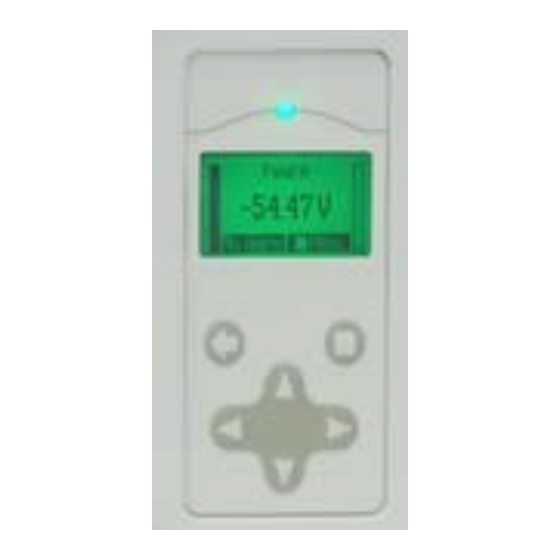
VIM1EC Meter
Warning: Hazardous energy and voltages are present in a powered BDFB. Avoid contact with the DC buses.
When making connection to energized DC buses place insulating material to prevent contact with other DC buses and grounded metal.
Before getting started, have the following tools and information available:
IP Address and other network information from Systems Administrator
•
PC or Laptop with RS-232, and Easyview2* installed
•
RS-232 cable
•
•
Torque wrench - 0-240 in-lb / 28 Nm (Gateway installation only)
Screw Driver - Phillips #2 (retrofit only)
•
Socket - 5/16" (retrofit only)
•
*EasyView2™ is the graphic user interface (GUI) ABB provides for local serial port access to controllers (see
Reference Documents).
Installation Steps
Ethernet access to BDFB Meter VIM1EC may be implemented via a Gateway card (factory-installed or
field-installed), or via a Millennium® II or Pulsar Plus controller.
Start with the step indicated in this table for the equipment that you are installing.
Installing
Gateway Assembly
VIM1EC Meter
Page 1
© 2023 ABB. All rights reserved.
Gateway Assembly 150047915 and 150050054
Start with Step
R1
V1
BDFB Gateway_QSG
Gateway Assembly 150050351
Skip if
Not installing a Gateway Assembly
Not installing a VIM1EC Meter
Rev. 2.0
Advertisement

Related Manuals for ABB VIM1EC


Summary of Contents for ABB VIM1EC
- Page 1 • Socket - 5/16” (retrofit only) • *EasyView2™ is the graphic user interface (GUI) ABB provides for local serial port access to controllers (see Reference Documents). Installation Steps Ethernet access to BDFB Meter VIM1EC may be implemented via a Gateway card (factory-installed or field-installed), or via a Millennium®...
-
Page 2: Component Location
VIM1/VIM1EC meter) 480 PNG 63k Wiring Diagram VIM1EC meter is connected via RS485 daisy-chain network either to a GPS system equipped with Millennium® I or Pulsar Plus controller or to a Gateway Assembly. RS485 Network: RS485 connection to previous RS485 device First VIM1EC connects to either a Gateway or to a GPS system RS485 network. - Page 3 Rear mounted Gateway Assembly: route the cables along the bracket connecting the front and back of the BDFB to keep them out of the path of the load wires. 6. Replace the top BDFB rear access panel. Page 3 © 2023 ABB. All rights reserved. BDFB Gateway_QSG Rev. 2.0...
- Page 4 6. Configure password under Settings Passwords. Go to Step V1 if installing a VIM1EC Meter. Go to Step V3 if connecting to an existing VIM1EC Meter. Install VIM1EC Meter-V Steps Step V1 - Record Configuration of Existing VIM1 Meter See Information VIM1EC Meter for Meter Parameters table and Menu Map.
- Page 5 SYSTEM PARAMETERS DEVICE ID 3. Confirm that the Gateway is powered up and communicating to the VIM1EC. The LED located in the lower left side of the Gateway card should be green. If LED is off, red, or yellow use the VIM1EC front panel to check and clear alarms •...
- Page 6 4. Login as user- Password: lineage 5. Confirm Gateway is connected to the VIM1EC by navigating to Home ► Distribution Bay Status to make sure you can see the data for every BDFB load for each connected the VIM1EC. Installation Completed. Information: VIM1EC Meter Each load bus is equipped with a shunt: 1500 A for G7 and G8, 1600 A for G101 and G102.
- Page 7 Combined Load Load Available Load Power Loss Load overload Type Load Overload Load Overload Delay Assigned Circuits Start Lamp Test Clear Latched Events Start Alarm Test Device ID Page 7 © 2023 ABB. All rights reserved. BDFB Gateway_QSG Rev. 2.0...
- Page 8 • Installation Environment - Install in Network Telecommunication Facilities, OSP, or where NEC applies. Reference Documents These documents are available at www.abbpowerconversion.com 4530236P 6420883P Kit 5069 BDFB VIM1EC Retrofit CC848815341 Pulsar Plus Controller Family Product Manual CC850018552 H569-445 Battery Distribution Fuse/Circuit Breaker Bay (BDFB/BDCBB) ESAPP VIM1 Smart Distribution Monitor—VIM1...
- Page 9 QUICK START GUIDE NOTES Page 9 © 2023 ABB. All rights reserved. BDFB Gateway_QSG Rev. 2.0...
- Page 10 QUICK START GUIDE NOTES Page 10 © 2023 ABB. All rights reserved. BDFB Gateway_QSG Rev. 2.0...
- Page 11 – in whole or in parts – is to purchase orders, the agreed particulars shall prevail. forbidden without prior written consent of ABB. ABB does not accept any responsibility whatsoever for potential errors or possible lack of information in this Copyright©...