
Related Manuals for ABB LVS Digital


Summary of Contents for ABB LVS Digital
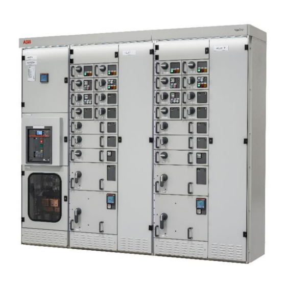
- Page 1 — D ISTR I B U TI O N S O LU T I O N S LVS Digital with UMC Motor Controller Interface Manual Profibus...
- Page 2 ABB products. The presence of any such description of a standard or reference to a standard is not a representation that all of the ABB products referenced in this document support all of the features of the described or referenced standard. In order to determine the specific features supported by a particular ABB product, the reader should consult the product specifications for the particular ABB product.
-
Page 3: Table Of Contents
TA BLE O F CO NT ENTS — Table of Contents 1. General ............................1 1.1. Target Group ..........................1 1.2. Use of Warning, Caution, Information and Tip icon ............. 1 Terminology ..........................2 Related Documentation ......................5 1.4.1 PROFIBUS additional guidelines ................5 2. - Page 4 TA BLE O F CO NT ENTS 7.6.1 Power-On procedure ....................35 7.6.2 Power On the control voltage supply ..............35 7.6.3 Confirm operation ....................35 8. Data Mapping ..........................36 User Data Map ........................... 36 Default Data Map ........................36 8.2.1 Cyclic Data Communication (DP-V0) ..............
- Page 5 Figure 11 Digital Gateway directly connected to LVS Digital Edge Gateway ........18 Figure 12 Network connection of Digital Gateway and LVS Digital Edge Gateway...... 19 Figure 13 Example, showing 3rd party Network Switch and 3rd party NTP Server in a Switchgear Control Network ........................
- Page 7 LIST OF TAB LES — List of Tables Table 1 Digital Gateway Profibus Hardware .................... 7 Table 2 Digital Gateway Technical Data ....................7 Table 3 Front View Connectors, LED and Push Buttons ..............12 Table 4 Maximum segment cable length for RS485 ................23 Table 5 Maximum stub length for RS485 ....................23 Table 6 Serial Redundant Link Cable ordering code ................
-
Page 9: General
Digital Gateway. Furthermore, the document provides information for control system and application engi- neers how to integrate LVS Digital [Upgrade] as Fieldbus component into PLC or higher-level Process Control Systems. It is assumed that the reader of this manual is familiar with basic terms of Fieldbus and con- trol communication (e.g. -
Page 10: Terminology
T ERM IN OLOGY G ENER A L performance leading to personal injury or death. It is therefore, imperative that you comply fully with all Warning and Caution notices. Terminology List of the terms, acronyms, abbreviations and definitions that the document uses. Abbreviation Term Description... - Page 11 Motor Control Centre Common term for switchgear used for motor con- trol and protection. MNavigate Configuration and parameterization tool for LVS Digital Modular Low Voltage Switchgear family from ABB MODBUS Fieldbus communication protocol MODBUS RTU Fieldbus communication protocol MODBUS TCP/IP...
- Page 12 T ERM IN OLOGY G ENER A L PROFIBUS-DP Fieldbus communication protocol with cyclic data transfer (V0). PROFIBUS-DP/V1 Fieldbus communication protocol, extension of PROFIBUS- DP allowing acyclic data transfer and multi master (V1). PROFIBUS-DP/V2 Fieldbus communication protocol, extension of PROFIBUS- DP allowing time stamp and communi- cation between master and slave (V2).
-
Page 13: Related Documentation
1.4 Related Documentation 2CDC194003D0202 Technical Description FBP Fieldbus Plug MTQ-22FBP 1TGC908001 ABB Ability Condition Monitoring for electrical systems - CMES - User Manual 1TNA810039 Manufacturing Instruction - Installation of MService and MNS Digital Gateway in MNS... -
Page 14: Introduction
One Digital Gateway can communicate internally to up to 128 UMC / field devices by Modbus TCP. If more than 128 UMC / field devices are installed, then additional Digital Gateway have to be configured. Figure 2: LVS Digital System Configuration with UMC 1 TG C90 80 04... -
Page 15: Hardware Types And Technical Data
I NTR OD UCT IO N HAR DWAR E T YP ES AND T ECHNI CA L DATA 2.1 Hardware Types and Technical Data The configuration of Digital Gateway depends on the selected communication protocol to the DCS. For the Profibus communication to DCS the hardware shown in the table below is appli- cable Fieldbus Protocol Profibus... -
Page 16: Profibus Standard
The three types of protocols are: PROFIBUS FMS, DP and PA. Only the two protocol types DP and PA are important for process automation, whereas only DP is used in LVS Digital PROFIBUS DP: PROcess Fieldbus for the Decentralized Periphery The PROFIBUS DP (RS 485) is responsible for communication between the Controller level of a process automation system and the decentralized periphery in the field. -
Page 17: Diagnostic
I NTR OD UCT IO N PR OF IBU S DP -V0 2.3.2 Diagnostic In addition to the cyclic data the PROFIBUS slave unit provides diagnostic data. With this diagnostic data the slave can indicate errors or warnings on the slave unit, the I/O-units or the I/O-channels. -
Page 18: Profibus Dp-V1
PR OF IBU S DP -V1 I NTR OD UCT IO N 2.4 PROFIBUS DP-V1 2.4.1 Acyclic Data Communication The key feature of version DP-V1 is the extended function for acyclic data communication. The acyclic data communication is mainly used for configuration and parameterization purpose. -
Page 19: Interfaces
I NT ER FACES F RO NT VI EW — 3. Interfaces 3.1 Front View PROFIBUS Connector Redundancy connector – Serial 1 Modbus RTU connector – Serial 2 Figure 5 Digital Gateway front view PROFIBUS DP PROFIBUS – upper LED, yellow PROFIBUS Communication running PROFIBUS –... -
Page 20: Table 3 Front View Connectors, Led And Push Buttons
F RO NT VI EW I NT ER FACES LAN 1 – LED right, yellow Communication Ethernet LAN 1 LAN 2 LAN 2 Interface (Switchgear Control Network) LAN 2 – LED left, green Link LAN 2 active LAN 2 – LED right, yellow Communication Ethernet LAN 2 LAN 3 LAN 3 Interface (Not used) -
Page 21: Power Supply
I NT ER FACES P OWER SUPP LY Power Supply The Digital Gateway requires 24V DC supply voltage. The connection is on the left side of the device with terminal plugs: • Terminal 1 connects to +24V DC • Terminal 2 connects to 0V DC 1 - Power Supply +24VDC 2 - Power Supply 0VDC Figure 6 Power Supply Connector... -
Page 22: Digital Gateway Installation
D IG ITA L GAT EWAY MO UNT ING D IG ITA L GAT EWAY I NSTA LLAT IO N — 4. Digital Gateway Installation 4.1 Digital Gateway Mounting The Digital Gateway is installed inside the switchgear on a Digital Gateway mounting kit (part ID: 1TNA704001R0003) which is housed in an 8E withdrawable module compartment of the MNS cubicle. -
Page 23: Cf Card Installation
CF card shall be inserted with the correct side up and with care as the card is mechanically coded and insertion should not be forced. The following example shows the ABB standard CF card. Figure 8 CF Card Insertion Figure 9 CF Card Insertion Detail... -
Page 24: Communication Interface Connection
S WITCHG EAR B US NET WORK COM MU NI CAT IO N I NT ERFACE CONNECTI ON — 5. Communication Interface Connection 5.1. Switchgear Bus Network The communication between Digital Gateway and UMC is established via Modbus TCP proto- col. -
Page 25: Switchgear Control Network
Examples of connections are shown in the following figures. All System configuration tools (e.g. MNavigate) and system components (LVS Digital Edge Gateway, Time Server) are con- nected to this network (see Figure 2). The cable shall be CAT5 / CAT6 depending on require- ments based on the selected Ethernet communication speed. -
Page 26: Connection Examples Of Switchgear Control Network
On the Digital Gateway, the cable must be connected to the LAN2 Ethernet port, on CMES Edge the cable must be connected to the designated Ethernet connector. The cable type is CAT5 or higher. Figure 11 Digital Gateway directly connected to LVS Digital Edge Gateway 1 TG C90 80 04... -
Page 27: Figure 12 Network Connection Of Digital Gateway And Lvs Digital Edge Gateway
Digital Gateway connected to Switchgear Control Network providing facility to connect addi- tional Digital Gateway and other system tools and components (e.g. LVS Digital Edge Gate- way, Web browser, Time Server, configuration tool, etc.). A net-work switch has to be installed in the plant. -
Page 28: Time Synchronization
Gateway and it may require a time server in the Switchgear Control Network. The protocol used for time synchronization is the standard Network Time Protocol (NTP). Time Sync must be activated through the ABB Engineering Tool. 5.3.1 Option 1 A standard network component is installed which can provide the time signal as NTP Server. -
Page 29: Option 2
COM MU NI CAT IO N I NT ERFACE CON N ECTI ON T IM E SYNCH RO NI ZAT IO N 5.3.2 Option 2 One Digital Gateway in the network is configured as NTP Server (Time Sync mode = RTC). In this case the date and time for this Digital Gateway must be set through the web interface. -
Page 30: Fieldbus
F I ELD BU S COM MU NI CAT IO N I NT ERFACE CONNECTI ON 5.4 Fieldbus 5.4.1 PROFIBUS The physical medium for PROFIBUS-DP is RS-485, which allows 32 nodes in a single segment and 125 nodes in a network using 4 segments. Segments must be separated by using Repeater. -
Page 31: Table 4 Maximum Segment Cable Length For Rs485
COM MU NI CAT IO N I NT ERFACE CON N ECTI ON F I ELD BU S For LVS Digital Upgrade solution for INSUM 2, maximum 48 UMC devices can be con- nected to a Digital Gateway. General PROFIBUS network information:... -
Page 32: Redundancy
R EDU NDA NT AR CH IT ECTURE R EDU NDA NCY — 6. Redundancy 6.1 Redundant Architecture A redundant system requires two Digital Gateway connected to the same internal switchgear bus. One Digital Gateway acts as Primary and the other acts as a Backup. The primary Digital Gateway polls the UMC via internal Modbus TCP and is responsible for sending the switching commands, as well as reading the information fed back from the UMC via the Digital Gateway. -
Page 33: Redundancy Configuration
R EDU NDA N CY R EDU NDA NCY CONFIG UR AT IO N available from the Backup Digital Gateway which will become the Primary Digital Gateway af- ter the switch over. To ensure the highest availability of the communication between Digital Gateway and UMC a ring topology is recommended. -
Page 34: Digital Gateway Redundant Configuration
The steps of configuring the redundant Digital Gateway is as following: 1. Set the Ethernet IP address of LAN1 and LAN2 for Primary and Backup LVS Digital Gate- way. -
Page 35: Figure 19 Mnavigate Fieldbus Slave Address Parameterization For Primary And Backup Digital Gateway
R EDU NDA N CY R EDU NDA NCY CONFIG UR AT IO N • It is essential that the IP address setting for LAN 2 of Primary and Backup Digi- tal Gateway is different (e.g. Primary = 192.168.200.100 / Backup = 192.168.200.101). -
Page 36: Handling Of Redundancy Faults
HA ND LIN G OF R EDU NDA N CY FAULTS R EDU NDA NCY 6.3 Handling of redundancy faults Both Digital Gateway always supervise the redundancy conditions, detecting faults and problems according following table: Event Action PLC or DCS connection interrupted for more Redundancy change over if backup Digital than 1 second to Primary Digital Gateway Gateway has an active PLC or DCS connec-... -
Page 37: Mview / Web Interface
R EDU NDA NCY MV I EW / WEB I NT ERFACE 6.4 MView / Web Interface In a dual redundant configuration, the MView is connected via the same Ethernet net- work to both Primary and Backup Digital Gateway If a changeover takes place, the current Primary will become the Backup (if still functioning) and the Backup will become Primary Digital Gateway. -
Page 38: Configurations
The parameters must be loaded onto the Compact Flash (CF) card using MNavigate tool be- fore powering up. After successful communication between MNavigate and LVS Digital Gateway (either direct or via network) the parameters can then be changed from MNavigate through the network. -
Page 39: Settings - Ip Configuration
CO NF IG UR AT IO NS S ET T ING S – IP CONFI GUR AT IO N Settings according to MTQ22 FBP Default Gateway LAN3 192.168.171.1 addressing RTC, RTC=internal clock, NTP=if external Time Synchronization NTP server is available Settings according to network Time Server Address 0.0.0.0... -
Page 40: Definition Of Ip Addresses
S ET T ING S – IP CON FI GUR AT IO N CO NF IG UR AT IO NS 7.2.1 Definition of IP Addresses An IP Address is a required setting in order to allow data communication in an Ethernet net- work. -
Page 41: Settings - Profibus Communication
Configuration 124 write definition from the GSD file. 120 read – 60 write 32 read – 16 write Only for LVS Digital Upgrade INSUM 2 Gsd 165A solution : INSUM 2 Gsd 067e Support of INSUM 2 GSD for INSUM 2 Upgrade solution... -
Page 42: Addressing
PROFIBUS communication. The Digital Gateway does not support address setting / editing from the PROFIBUS Master. The address must be defined with the LVS Digital parameter ”PROFIBUS Slave Address“. If more than 32 devices are connected to a segment, repeater devices have to be used. Such repeater counts as one Slave within a segment without using an address number. -
Page 43: Failsafe
CO NF IG UR AT IO NS FAI LS AF E 7.5 Failsafe In circumstances where a disturbance in the MODBUS communication network needs to be monitored it is possible to select a ‘Failsafe’ state for each UMC. This state must be defined as a parameter for each UMC separately. -
Page 44: Data Mapping
8.1 User Data Map All available data in a UMC can be assigned to the corresponding register addresses by using the MNavigate Mapping Tool. This is a proprietary tool for ABB to program the PROFIBUS registers according to customer requirements. -
Page 45: Cyclic Data Communication (Dp-V0)
• 244 Read - 124 Write enables communication with 60 UMC • 120 Read - 60 Write • 32 Read - 16 Write • Insum2 Gsd165A (used only in LVS Digital Upgrade) • Insum2 Gsd067E (used only in LVS Digital Upgrade) 8.2.1 Cyclic Data Communication (DP-V0) 8.2.1.1 Monitoring (Inputs from field device to master, class 1) -
Page 46: Status Bit Explanation
D EFAULT DATA MAP DATA MAPP ING 8.2.2 Status Bit Explanation Byte Description Byte 0 Trip New 0 = no trip condition 1 = any trip condition of the Bit 7 available protection and su- pervision functions Byte 0 Alarm 0 = no alarm 1 = any warning of the avail- Bit 6... -
Page 47: Commands (Output To Field Device From Master)
DATA MAPP IN G D EFAULT DATA MAP Byte 1 0 = General Purpose Input 3 1 = General Purpose Input 3 GPI 3 Bit 4 not active is active Byte 1 0 = General Purpose Input 2 1 = General Purpose Input 2 GPI 2 Bit 3 not active... -
Page 48: Command Bits Explanation
D EFAULT DATA MAP DATA MAPP ING 8.2.4 Command Bits Explanation Byte Description Byte 0 Bit 7 reserved Byte 0 Bit 6 Trip Reset 1 = to reset any trip condition Byte 0 Bit 5 Set CA to Remote 1 = Instructs UMC to accept control commands from remote location (PLC / PCS) Byte 0 Bit 4 reserved... -
Page 49: Handling Of Commands And Priority
DATA MAPP IN G D EFAULT DATA MAP 8.2.5 Handling of Commands and Priority Command priority • If the Off bit is set Run Forward and Run Reverse are ineffective. Off command has highest priority. • If Run Forward and Run Reverse are set, both commands are ineffective. No command is sent to UMC •... -
Page 50: Redundant Digital Gateway Profibus Data
D EFAULT DATA MAP DATA MAPP ING 8.2.6 Redundant Digital Gateway Profibus Data The following additional data mapping is provided for a redundant data interface to determine the status of Digital Gateway (Primary/Backup, Redundancy Error). It is also pos- sible to send commands to force a change-over. Byte Bit 7 Bit 6... -
Page 51: Control Access
D EFAULT DATA MAP 8.2.7 Control Access Control Access (CA) is a mechanism within LVS Digital to define and determine which user in- terface has control rights to operate the UMC modules. These interfaces are defined below in command handling. Control Access rights can be given, for example, by a specific command sent to switch operation rights from push-button (hardwired to UMC) to any other interface connected via the Digital Gateway (e.g. - Page 52 D EFAULT DATA MAP DATA MAPP ING CA BusLocal will be active if Auto Mode is not set and the Bus Local command bit goes from 0 to 1. Hardware-Local overrides all other CA Levels. It is not possible for the DCS or MView to take control when the UMC is set to HW-Local.
-
Page 53: Acyclic Data Communication (Dp-V1 -Master Class 1)
DATA MAPP IN G D EFAULT DATA MAP 8.2.8 Acyclic Data Communication (DP-V1 –master class 1) The PROFIBUS DP-V1 function will provide additional asynchronous data transferred from each UMC. The data is listed in the tables below. The DPV1 read request requires the following three parameters: Slot number: •... -
Page 54: Table 20 Default Dp-V1 Data
D EFAULT DATA MAP DATA MAPP ING Byte 34 – Byte 37 ULONG Apparent Power [VA] Byte 38 – Byte 41 ULONG Energy Used [kWh] Byte 42 – Byte 43 UWORD_10 Frequency [Hz] Byte 44 –Byte 45 UWORD Max Current at Startup [%] Byte 46 –... -
Page 55: Table 22 Extended Status Byte 59
DATA MAPP IN G D EFAULT DATA MAP BYTE 59 Description Remark Bit 0 Any Alarm Set when any Alarm is present Bit 1 New Trip Set when any New Trip is present Bit 2 Reserved Bit 3 Reserved Bit 4 Reserved Bit 5 Reserved... -
Page 56: Table 24 Extended Status Byte 61
D EFAULT DATA MAP DATA MA PP ING BYTE 61 Description Remark Bit 0 HW -Local UMC accepts control commands from the hardwired inputs on UMC, when the respective Local control input is set to true. Bit 1 Reserved Bit 2 BUS-Local UMC accepts control commands from a device on the switchgear control net-... -
Page 57: Troubleshooting And Maintenance
TR OUB LESHOOT IN G A ND MA INT ENA NCE D IG ITA L GAT EWAY LED I ND ICATI O N — 9. Troubleshooting and Maintenance 9.1 Digital Gateway LED Indication LED indication Description Additional Information / Actions Digital Gateway is running Ok Digital Gateway is... - Page 58 D IG ITA L GAT EWAY LED I ND ICATI O N TR OUB LESHOOT ING A ND MA INT ENA NCE Additional Information / Actions LED indication Description Possible cause could be a interrupted or Error in Digital Gate- disturbed communication between way XML MNavigate and Digital Gateway while down-...
-
Page 59: Table 25 Digital Gateway Led Indication
TR OUB LESHOOT IN G A ND MA INT ENA NCE D IG ITA L GAT EWAY LED I ND ICATI O N Description Additional Information / Actions LED indication General DCS fault Please check if Digital Gateway hard- ware (the identity number) matches to the (only available if con- project specification (e.g. -
Page 60: Troubleshooting
TR OUB LESHOOT IN G TR OUB LESHOOT ING A ND MA INT ENA NCE 9.2 Troubleshooting Problem Solution No access to Check if the correct IP address in the address bar of the web browser has Digital Gateway been entered. with the web interface or MNavigate... -
Page 61: Table 26 Digital Gateway Troubleshooting
TR OUB LESHOOT IN G A ND MA INT ENA NCE TR OUB LESHOOT ING Problem Solution No communica- Check if cable connection, shielding, and termination are all in line with the tion between DCS requirements of Profibus standard. and Digital Gate- Check if slave address settings are correctly parameterized in MNavigate and the parameters have been downloaded to the Digital Gateway. - Page 63 Revision History Rev. Page Change Description Date / Initial Initial release 2020-08-17 EPDS/MM 0203 07 Dimension of Digital Gateway corrected (chapter 2.1) 2020-10-02 EPDS/FS 0204 44 Remote command revised 2021-01-27 EPDS/mm...
- Page 64 — Visit us http://www.abb.com/mns...