ABB MINI-MAG 10D1475 Series Instruction Manual
Magnetic flowmeters
Hide thumbs
Also See for MINI-MAG 10D1475 Series:
- Installation instructions manual (10 pages) ,
- Instruction manual (55 pages) ,
- Instruction manual (52 pages)

Related Manuals for ABB MINI-MAG 10D1475 Series


Summary of Contents for ABB MINI-MAG 10D1475 Series
- Page 1 INSTRUCTION MANUAL MAGNETIC FLOWMETERS 10D1475 Design Levels J & S Sizes 1/10 through 4 Inches MINI-MAG MAGNETIC FLOWMETER PN25006A...
- Page 2 Selection of materials and/or equipment is at the sole risk of the user of this publication. This document contains proprietary information of ABB Inc., and is issued in strict confidence. Its use, or reproduction for use, for the reverse engineering, development or manufacture of hardware or software described herein is prohibited.
-
Page 3: Table Of Contents
10D1475 MINI-MAG MAGNETIC FLOWMETER INSTRUCTION MANUAL Table of Contents SAFETY SUMMARY ........... . . I READ FIRST . - Page 4 10D1475 MINI-MAG MAGNETIC FLOWMETER INSTRUCTION MANUAL 4.4 Jumper Selections ............4-6 4.4.1 Model 10D1475S .
- Page 5 10D1475 MINI-MAG MAGNETIC FLOWMETER INSTRUCTION MANUAL List of Figures FIGURE 1-1. INTEGRAL 10D1475J FLOWMETER......... 1-1 FIGURE 1-2.
-
Page 6: Safety Summary
Some process upsets may cause injury or damage. RETURN OF EQUIPMENT. All Flowmeters and/or Signal Converters being returned to ABB for repair must be free of any hazardous materials (acids, alkalis, solvents, etc.). A Material Safety Data Sheet (MSDS) for all process liquids must accompany returned equipment. - Page 7 10D1475 MINI-MAG MAGNETIC FLOWMETER INSTRUCTION MANUAL SPECIFIC Do not use graphite gaskets. Under certain conditions they may CAUTIONS cause an electrically conductive layer to form on the inside wall of the meter, causing meter operation to degrade. (pg. 2-8) Some of the IC devices used in the signal converter are static sensitive and may be damaged by improper handling.
- Page 8 MANUEL DE MISE EN ROUTE. Ne pas installer, maintenir ou utiliser cet équipement sans avoir lu, compris et suivi les instructions et manuels de ABB, dans le cas contraire il y a risque d’entraîner blessures ou dommages. RISQUE DE CHOC ÉLECTRIQUE Les équipements alimentés en courant alternatif constituent...
- Page 9 10D1475 MINI-MAG MAGNETIC FLOWMETER INSTRUCTION MANUAL SPÉCIFIQUES N’utilisez pas les garnitures de graphite. Dans certaines con- ATTENTIONS ditions elles peuvent causer une couche électriquement con- ductrice à la forme sur le mur intérieur du mètre, faisant dégrader l’exécution de mètre. (pg. 2-8) Certains Circuits Intégrés utilisés dans le convertisseur sont sensibles à...
-
Page 10: Read First
Read these instructions before starting installation; save these instructions for future reference. Contacting the factory Should assistance be required with any of the manufacturer’s products, contact the following: Telephone: Automation Services Call Center 1-800-HELP-365 E-Mail: ins.techsupport@us.abb.com... - Page 11 10D1475 MINI-MAG MAGNETIC FLOWMETER INSTRUCTION MANUAL The NEMA 4X rating applies to the meter body and electronics enclosure only. The following accessories (if supplied) may not meet NEMA 4X unless specifically ordered as NEMA 4X: • meter flanges • meter installation hardware: studs, nuts, bolts •...
-
Page 12: Introduction
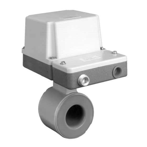
10D1475 MINI-MAG MAGNETIC FLOWMETER INSTRUCTION MANUAL 1.0 INTRODUCTION 1.1 General The Series 10D1475 MINI-MAG Magnetic Flowmeter is an electromagnetic liquid flow rate detector. The meter uses the characteristics of a conductive liquid to generate an induced voltage, directly proportional to flow rate, as the liquid passes internal electrodes. The resultant voltage is applied to a solid state electronics package that conditions it to an output signal compatible with conventional receiving equipment. - Page 13 10D1475 MINI-MAG MAGNETIC FLOWMETER INSTRUCTION MANUAL The associated electronics package is called the signal converter and may be either integrally or remotely mounted. Typical integral MINI-MAG Magnetic Flowmeters are shown in Figures 1-1 & 1-2. The integral housing shown contains a 50XM1000 electronics module. Remote models 10D1475J & 10D1475S are furnished with remote 50XM1000 electronics.
-
Page 14: Model Number Breakdown
10D1475 MINI-MAG MAGNETIC FLOWMETER INSTRUCTION MANUAL 1.2 Model Number Breakdown Refer to the product’s data sheet or the data tag on the equipment for the model number of the instrument furnished. The details of a specific number are shown on the following two pages. INTRODUCTION... - Page 15 10D1475 MINI-MAG MAGNETIC FLOWMETER INSTRUCTION MANUAL Order Number 10D1475 _ N __ _ _ 2 _ _ _ _ _ _ _ _ _ _ _ _ Design Level 1/10 - 3/8 Inches 1/2 - 4 Inches Liner Material Tefzel (ETFE) Meter Size - inches (mm) 1/10 5/32...
- Page 16 10D1475 MINI-MAG MAGNETIC FLOWMETER INSTRUCTION MANUAL Order Number 10D1475 _ N __ _ _ 2 _ _ _ _ _ _ _ _ _ _ _ Enclosure Classification IEC 529, IP65, NEMA 4X Continuous Submergence: IEC 529, IP68, NEMA 4X, 33 ft H (10 m H O) Continuous Duty.
-
Page 17: Specifications
10D1475 MINI-MAG MAGNETIC FLOWMETER INSTRUCTION MANUAL 1.3 Specifications Power Requirements See Section 1.2 Model Number Breakdown Power Consumption Refer to signal converter instruction manual Flowmeter Characteristics Meter Size/Flow Capacity TABLE 1-1. METER CAPACITY Flow Ranges 0 to value tabulated METER Meter Size Minimum Maximum... - Page 18 10D1475 MINI-MAG MAGNETIC FLOWMETER INSTRUCTION MANUAL Enclosure Classification with NEMA 4X, IEC 529 IP65 or without Signal Converter Accidental Submergence IEC 529 IP67, 33 feet H O/48 h (10 m H O /48 h) Continuous Submergence IEC 529 IP68, 33 feet H O (10 m H Ambient Temperature Limits MODEL...
-
Page 19: Table 1-2. Meter Weights
10D1475 MINI-MAG MAGNETIC FLOWMETER INSTRUCTION MANUAL Vacuum full vacuum at 212 F (100 C) for 1/10 - 3 in. (3 - 80 mm) sizes full vacuum at 176 F (80 C) for 4 in. (100 mm) size Meter Capacity specified on Flowmeter data tag (equal to max flow capacity in engineering units). - Page 20 10D1475 MINI-MAG MAGNETIC FLOWMETER INSTRUCTION MANUAL Vibration Limit Integrally Mounted *5 to 14 Hz, 0.10 inch, 14 to 2000 Hz, 1 g Signal converter must be remotely mounted if these limits are exceeded. Remotely Mounted 5 to 14 Hz, 0.20 inch 14 to 2000 Hz, 1.5 g Materials of Construction Meter Liner...
-
Page 21: Installation
10D1475 MINI-MAG MAGNETIC FLOWMETER INSTRUCTION MANUAL 2.0 INSTALLATION 2.1 Inspection All Model 10D1475 Magnetic Flowmeters are shipped in heavy duty containers. An itemized list of all items included in the shipment is attached to the shipping container. Depending upon the particular model specified, the shipment will generally consist of: •... -
Page 22: Mounting
10D1475 MINI-MAG MAGNETIC FLOWMETER INSTRUCTION MANUAL Outline dimensions of the magnetic flowmeters are given in Figures 2-1 through 2-3. When applica- ble, provide access for occasional servicing of the integrally mounted signal converters. At least five inches of overhead clearance is required for cover removal as shown in Figure 2-1. Observe the various clearances given on the drawings. - Page 23 10D1475 MINI-MAG MAGNETIC FLOWMETER INSTRUCTION MANUAL INSTALLATION...
- Page 24 10D1475 MINI-MAG MAGNETIC FLOWMETER INSTRUCTION MANUAL INSTALLATION...
- Page 25 10D1475 MINI-MAG MAGNETIC FLOWMETER INSTRUCTION MANUAL INSTALLATION...
-
Page 26: Pipe Connections
10D1475 MINI-MAG MAGNETIC FLOWMETER INSTRUCTION MANUAL FIGURE 2-4. RECOMMENDED PIPING ARRANGEMENT 2.3.3 Pipe Connections The Model 10D1475 Magnetic Flowmeter has a wafer type body designed for mounting between adjacent pipe flanges. Most commonly used ANSI, BS and DIN type flanges can be accommodated. Mounting hardware (studs, nuts, gaskets and the flange adaptor device(s) for the particular flange type and rating specified) is supplied for use with common ANSI flanges. -
Page 27: Figure 2-5. Bolt Tightening Sequence
10D1475 MINI-MAG MAGNETIC FLOWMETER INSTRUCTION MANUAL For 4-bolt and 8-bolt flanges, tighten the flange bolts in a "star" pattern as shown in Figure 2-5 to avoid localized stresses on the gaskets. The bolts and nuts should be tightened approximately 50% during the first pass, approximately 80% during the second pass and to full tightness during the third pass. -
Page 28: Gaskets
10D1475 MINI-MAG MAGNETIC FLOWMETER INSTRUCTION MANUAL 2.3.4 Gaskets Use only the gaskets supplied with the instrument. The gaskets supplied with the meter are the proper size for the meter size and type specified. When installing the meter it is important that the correct size gaskets be utilized. -
Page 29: Figure 2-6. Meter Mounting Diagram
10D1475 MINI-MAG MAGNETIC FLOWMETER INSTRUCTION MANUAL ADAPTER SLEEVE PART NUMBERS FIGURE 2-6. METER MOUNTING DIAGRAM INSTALLATION... -
Page 30: Grounding Procedure
10D1475 MINI-MAG MAGNETIC FLOWMETER INSTRUCTION MANUAL 2.4 Grounding Procedure 2.4.1 General Satisfactory operation of the Magnetic Flowmeter system requires that careful attention be paid to proper grounding techniques. Meter grounding requirements are a combination of standard ground- ing methods and grounding of the meter body to the process liquid. The grounding of the process liquid places an electrical short circuit through the meter body, thereby routing any stray current around the process liquid rather than through it. -
Page 31: Figure 2-7. Grounding Procedure, Conductive Pipe
10D1475 MINI-MAG MAGNETIC FLOWMETER INSTRUCTION MANUAL FIGURE 2-7. GROUNDING PROCEDURE, CONDUCTIVE PIPE INSTALLATION 2-11... -
Page 32: Non-Conductive Or Insulated Pipeline
10D1475 MINI-MAG MAGNETIC FLOWMETER INSTRUCTION MANUAL 2.4.3 Non-Conductive or Insulated Pipeline For the Magnetic Flowmeter mounted in a non-conductive or liquid insulated pipeline (such as totally plastic pipe, ceramic lined iron pipe, or cast pipe with internal bitumastic coating), perform the grounding procedure outlined below. -
Page 33: Figure 2-9. Grounding Procedure, Non-Conductive Or Insulated Pipe
10D1475 MINI-MAG MAGNETIC FLOWMETER INSTRUCTION MANUAL FIGURE 2-9. GROUNDING PROCEDURE, NON-CONDUCTIVE OR INSULATED PIPE INSTALLATION 2-13... -
Page 34: Electrical Interconnections
10D1475 MINI-MAG MAGNETIC FLOWMETER INSTRUCTION MANUAL 2.5 Electrical Interconnections The Series 10D1475 Magnetic Flowmeter may be furnished with either an integrally or remotely mounted signal converter. Interconnection wiring is arranged differently for the two systems and is done in the customer connection boxes shown below for the 10D1475J integral & 10D1475Sinte- gral/remote meters. -
Page 35: Figure 2-11. Conduit Entry Seal Installation
10D1475 MINI-MAG MAGNETIC FLOWMETER INSTRUCTION MANUAL FIGURE 2-11. CONDUIT ENTRY SEAL INSTALLATION INSTALLATION 2-15... -
Page 36: Start-Up
10D1475 MINI-MAG MAGNETIC FLOWMETER INSTRUCTION MANUAL 3.0 START-UP The Series 10D1475 MINI-MAG Magnetic Flowmeter (which includes the integral or remote Signal Converter) is precision calibrated at the factory for the values stated on the instrument tag. If specific values were not specified, the meter is calibrated at a nominal maximum flow rate and for a 4-20 mA current output span. -
Page 37: Turn Power On
10D1475 MINI-MAG MAGNETIC FLOWMETER INSTRUCTION MANUAL 3.2 Turn Power On WARNING ELECTRICAL SHOCK HAZARD. Equipment powered by an AC line voltage presents a potential electric shock hazard. Servicing of the Magnetic Flowmeter or Signal Converter should only be attempted by a qualified electronics technician. -
Page 38: Electronics
10D1475 MINI-MAG MAGNETIC FLOWMETER INSTRUCTION MANUAL 3.6 Electronics Refer to Figures 3-3 through 3-5 for illustrations of integral and remote-mounted electronics mounted on the Primary BASE BOARD POWER CONNECTOR 686B630U01 ADAPTER PCB ATTACHES TO P1 FOR REMOTE CONFIGURATION (SEE INSET BELOW) GROUND TERMINAL INTERCONNECTION AND... -
Page 39: Figure 3-4. 1/2 Through 4 Inch Integrally Mounted Enclosure Without
10D1475 MINI-MAG MAGNETIC FLOWMETER INSTRUCTION MANUAL POWER CONNECTOR BASE BOARD GROUND TERMINAL INTERCONNECTION AND CUSTOMER CONNECTIONS FIGURE 3-4. 1/2 through 4 INCH INTEGRALLY MOUNTED ENCLOSURE WITHOUT CONVERTER MODULE [10D1475J] START-UP... - Page 40 10D1475 MINI-MAG MAGNETIC FLOWMETER INSTRUCTION MANUAL GROUND TERMINAL FIGURE 3-5. REMOTE PRIMARY PCB ASSEMBLY IN GENERAL PURPOSE OR FM CLASS I, DIV.2 HOUSING [10D1475J] START-UP...
- Page 41 10D1475 MINI-MAG MAGNETIC FLOWMETER INSTRUCTION MANUAL CABLE CONNECTIONS NOTE The figure shows electronics without encapsulation material. Normally the housing is filled with a silicone rubber encapsulant. FIGURE 3-5. TYPICAL EXPLOSION-PROOF OR CONTINUOUS SUBMER- GENCE PRIMARY FOR REMOTE MOUNTED SIGNAL CONVERTER START-UP...
-
Page 42: Functional Description
10D1475 MINI-MAG MAGNETIC FLOWMETER INSTRUCTION MANUAL 4.0 FUNCTIONAL DESCRIPTION The magnetic flowmeter body houses two signal electrodes and the flux producing magnet coils, as shown schematically in Figure 4-1. All primary intraconnection wiring is terminated at a printed circuit assembly located in the base of the meter housing. The Flowmeter provides two output signals to the associated signal converter: •... -
Page 43: Magnet Coil Drive Circuits
10D1475 MINI-MAG MAGNETIC FLOWMETER INSTRUCTION MANUAL This may be expressed mathematically as: (Equation #1) E s = α where: = induced electrode voltage B = magnetic field strength D = meter pipe diameter α = dimensionless constant V = liquid velocity Thus, the metered liquid constitutes a continuous series of conductive liquid disks moving through a magnetic field. -
Page 44: Operating Characteristics
10D1475 MINI-MAG MAGNETIC FLOWMETER INSTRUCTION MANUAL 4.2 Operating Characteristics 4.2.1 Liquid Variables 4.2.1.1 Liquid Conductivity The magnetic flowmeter requires a liquid conductivity of 5 microsiemens per centimeter or higher for operation. This minimum liquid conductivity requirement is not affected by the length of the signal interconnection cable when remote mounting of the signal converter is required, as long as the factory-supplied interconnection cable (with driven shields) is utilized. -
Page 45: Liquid Temperature
10D1475 MINI-MAG MAGNETIC FLOWMETER INSTRUCTION MANUAL TABLE 4-1. ELECTRODE DIAMETERS Meter Size Electrode Diameter inch inch 1/10 0.048 0.122 5/32 0.079 0.202 0.142 0.361 0.236 0.600 0.250 0.635 1 - 4 25 - 100 0.312 0.792 4.2.1.2 Liquid Temperature Having established the minimum liquid conductivity requirements for a given application, any liquid which exhibits equal or higher conductivity may be metered without concern for any system compen- sating adjustments. -
Page 46: Circuit Description
10D1475 MINI-MAG MAGNETIC FLOWMETER INSTRUCTION MANUAL 4.3 Circuit Description 4.3.1 Primary Signals The Model 10D1475J/S flowmeters use integral or remote 50XM1000 Converter electronics. As described in paragraph 4.1, the magnetic flowmeter body houses two signal electrodes and two flux producing magnet coils. Refer to the 50XM1000 Converter Instruction Manual for remote-configura- tion interconnection wiring diagrams. -
Page 47: Jumper Selections
10D1475 MINI-MAG MAGNETIC FLOWMETER INSTRUCTION MANUAL 4.4 Jumper Selections 4.4.1 Model 10D1475S For the integral-mounted converters, zero return and functions associated with the 50XM1000 signal converter are established by the movable jumpers at terminals A2 and B1 located on the lower left corner of the 686B623U01 Primary Board assembly. - Page 48 10D1475 MINI-MAG MAGNETIC FLOWMETER INSTRUCTION MANUAL FIGURE 4-2. 686B762U02 PRIMARY BOARD ASSEMBLY TABLE 4-2. 686B762U02 PCB JUMPER FUNCTIONS JUMPER NO. POSITION FUNCTION Zero Return 10 KHz Signal Reverse Pulse Signal GND for 10 KHz, Zero Return 9-10 COMMON for Reverse Pulse 2-4, 8-10 Remote Converter Integral Converter...
-
Page 49: Remote
10D1475 MINI-MAG MAGNETIC FLOWMETER INSTRUCTION MANUAL 4.4.2.2 Remote The remote version of Model 10D1475J Converter uses the smaller two-piece housing which con- tains two circuit board assemblies, the 686B789U01 CMF PCB assembly and the 686B790U01 Customer Connection PCB assembly. The 686B790U01 PCB interfaces to the remote 50XM1000 Converter via the supplied interconnection cable. -
Page 50: Maintenance
10D1475 MINI-MAG MAGNETIC FLOWMETER INSTRUCTION MANUAL 5.0 MAINTENANCE 5.1 General Except for an occasional performance verification check, there is no required routine maintenance for the Model 10D1475 meters. The flowmeter body is of all welded construction. In the event a malfunction occurs in the primary, the meter body must be replaced. -
Page 51: System Troubleshooting
10D1475 MINI-MAG MAGNETIC FLOWMETER INSTRUCTION MANUAL NOTE Operation and maintenance procedures for the 10D1475 signal converters are provided in the Instruction Manual supplied with the signal converter. When communicating in regard to replacement of a complete meter (with integrally mounted con- verter), the meter body, or the signal converter, it is important to refer to the complete instrument serial number to assure that the correct replacement will be supplied. -
Page 52: Static Test
10D1475 MINI-MAG MAGNETIC FLOWMETER INSTRUCTION MANUAL 5.3 Static Test If improper operation of the magnetic flowmeter is suspected, the following resistance measurements can be made to establish whether an electrical malfunction has occurred. A standard multimeter is suitable for making the resistance checks. These measurements can be made at the Connection board located in the base of the electronic housing. -
Page 53: Electrode Check
10D1475 MINI-MAG MAGNETIC FLOWMETER INSTRUCTION MANUAL 5.3.2 Electrode Check The electrode check is essentially a resistance measurement that can be made to establish that a short (or high resistance leakage path) does not exist between one, or both, electrodes and the meter body. -
Page 54: Parts
2 inch 3 inch 4 inch inch inch Suffix * To complete the part number, add suffix from table; e.g., 333J089U10 for 25mm (1 inch) meter with KLINGER SIL gaskets. For applications other than ANSI CLASS 150 Flanges contact ABB. PARTS... -
Page 55: Adapter Sleeves
10D1475 MINI-MAG MAGNETIC FLOWMETER INSTRUCTION MANUAL TABLE 6-3. GASKETS FOR METER BODY (2 required) KLINGER SIL C-4401--------Part Number 333J089___* TEFLON-------------------------Part Number 333J092___* Meter Size Flange 3 - 10 mm 15 mm 25 mm 40 mm 50 mm 80 mm 100 mm Rating ⁄... -
Page 56: Studs & Nuts
10D1475 MINI-MAG MAGNETIC FLOWMETER INSTRUCTION MANUAL 6.4 Studs & Nuts TABLE 6-5. STUDS & NUTS (1 Required) STEEL-----------------------------------Part Number 614B650___ * Meter Size Flange 3 - 10 mm 15 mm 25 mm 40 mm 50 mm 80 mm 100 mm Rating ⁄... - Page 57 The Company’s policy is one of continuous product improvement and the right is reserved to modify the information contained herein without notice. © 2003 ABB Inc. Printed in USA ABB Inc. ABB Instrumentation Ltd ABB Instrumentation S.p.A ABB Automation Products GmbH 125 East County Line Road Howard Road, St.