Advertisement
Quick Links
INSTRUCTION MANUAL
VARIABLE AREA FLOWMETERS
10A2235 Rev.5
1) Glass meter tubes have been designed to operate
up to maximum design working pressures listed
herein. This not to be construed as a certification
that the tubes will not break at any pressure. Inher-
ent material limitations can result in tube breakage
due to conditions beyond our control. For example,
glass is a brittle material which may break upon
impact; glass if subjected to thermal shock may
break; glass is notch sensitive in that scratches,
nicks or cracks may result in breakage when pres-
surized; incorrect installation or faulty operating
methods can cause tube breakage regardless of op-
erating pressure.
2) Glass meter tubes are not recommended for
either hot or strong alkalies, fluorine, hydrofluoric
acid, steam or water over 200
ter tubes should be periodically inspected for signs
of wear. Erosion, stress cracks, nicks or deep
scratches provide early warning for tube replace-
ment. With certain fluids, the glass may erode
evenly so wear is not visibly noticeable. If wear is
suspected, the tube should be replaced in order to
eliminate this potential cause of meter tube break-
age.
3) It is important that all materials of construction
be compatible with the service to which the Meter is
applied. It is especially important that "O" ring mate-
rial be compatible with the process fluid. Glass me-
ter tube breakage can occur in those meters using
an "O" ring as an internal seal if the improper mate-
rial is used. For example: VITON "O" RINGS MUST
NEVER BE USED FOR AMMONIA SERVICE; THE
CORROSIVE ATTACK OF AMMONIA ON VITON IS
EXTREME, CAUSING THE "O" RING TO SWELL
TO THE EXTENT OF BREAKING THE GLASS ME-
TER TUBE.
4) The Meter should never be subjected to exces-
sive vibration. Avoid the use of quick acting devices
in the fluid stream in order to prevent shock waves,
associated with such devices, from damaging the
meter.
5) The use of a pressure relief valve and/or a
rupture disc is recommended in the pipeline contain-
ing the Meter and located such to preclude glass
meter tube breakage in the event of an overpressuri-
zation of the line.
o
o
F (93
C). Glass me-
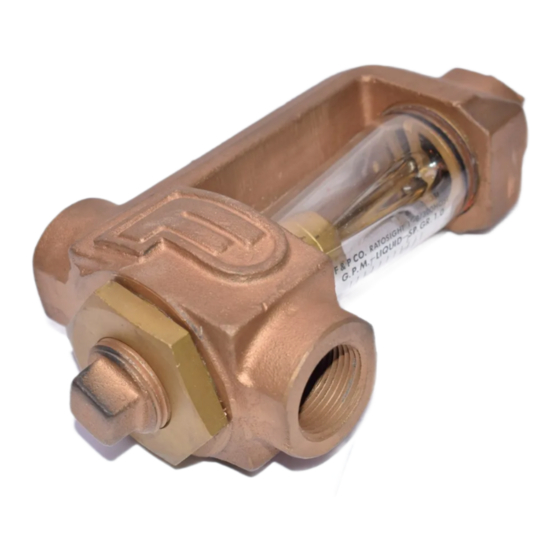
RATOSIGHT FLOW RATE INDICATORS
6) When applied to a high pressure gas cylinder, at
least two stepdown pressure regulators are to be
used between the Meter and the cylinder.
7) Remove pressure from the Meter before at-
tempting to remove the meter tube. 8) Be sure the
parts that serve to lock the meter end fittings in
place are secure. This should be checked before the
Meter is put into service or returned to service after
maintenance. Loose end fittings may result in glass
meter tube breakage.
9) The glass meter tube should be periodically
inspected and replaced if cracked, nicked, scratched
or worn.
Advertisement

Summary of Contents for ABB RATOSIGHT 10A2235
- Page 1 INSTRUCTION MANUAL VARIABLE AREA FLOWMETERS 10A2235 Rev.5 1) Glass meter tubes have been designed to operate RATOSIGHT FLOW RATE INDICATORS up to maximum design working pressures listed herein. This not to be construed as a certification that the tubes will not break at any pressure. Inher- ent material limitations can result in tube breakage due to conditions beyond our control.
- Page 2 * For pressure rating at other temperatures, contact the factory. NOTE The warning was changed since this Bulletin was last published as PN24289A Read these instructions before starting installation; save these instructions for future reference. Copyright 2002 ABB Inc. [May, 2002]...
-
Page 3: Installation
Installation The RATOSIGHT flow rate indicator is normally fur- If the float is received separately from the instru- nished for horizontal connections. However, vertical ment, insert it in the tube after removing the inlet connections or combination horizontal-vertical con- fitting. Figure 3 shows the correct float orientation nections may be made by changing the locations of and the reading edges. - Page 4 FIGURE 3. FLOAT READING EDGES FIGURE 4. OUTLINE DIMENSIONS...
- Page 5 The Company’s policy is one of continuous product improvement and the right is reserved to modify the information contained herein without notice. © 2002 ABB Inc. Printed in USA ABB Inc. ABB Instrumentation Ltd ABB Instrumentation S.p.A ABB Automation Products GmbH 125 East County Line Road Howard Road, St.


