
Related Manuals for ABB AC500 PLC


Summary of Contents for ABB AC500 PLC
- Page 1 HARDWARE MANUAL AC500 PLC System Assembly and Device Specifications for AC500 V2 Products...
-
Page 2: Table Of Contents
Table of contents — Table of contents Device Specifications............................. 4 1.1 Terminal Bases (AC500 Standard)......................4 1.1.1 TB51x-TB54x..........................4 1.1.2 TF501-CMS and TF521-CMS - Function Module Terminal Bases .......... 13 1.2 Processor Modules..........................20 1.2.1 AC500-eCo..........................21 1.2.2 AC500 (Standard)........................65 1.3 Communication Modules (AC500 Standard)................... - Page 3 Table of contents 2.4.1 Serial I/O Bus........................1178 2.4.2 Mechanical Encoding......................1181 2.4.3 Earthing Concept (Block Diagrams)..................1184 2.4.4 EMC-Conforming Assembly and Construction..............1186 2.4.5 Power Consumption of an Entire Station................1189 2.4.6 Recycling and Disposal......................1192 2.5 AC500-eCo............................1192 2.5.1 System Data AC500-eCo.....................
-
Page 4: Device Specifications
Device Specifications Terminal Bases (AC500 Standard) > TB51x-TB54x — 1 Device Specifications 1.1 Terminal Bases (AC500 Standard) For AC500-eCo processor modules and special AC500 (Standard) processor modules the terminal base cannot be removed. 1.1.1 TB51x-TB54x ● TB511-ARCNET: 1 processor module, 1 communication module, with network interface ARCNET BNC ●... - Page 5 Device Specifications Terminal Bases (AC500 Standard) > TB51x-TB54x I/O bus (10-pin, female) to electrically connect the I/O terminal units Slot for processor module Slots for communication modules (TB511-xxx: 1 slot, TB521-xxx: 2 slots, TB541-xx: 4 slots) Interface for FieldBusPlug, not for terminal base TB523-2ETH Power supply (5-pin terminal block, removable) Serial interface COM1 (9-pin terminal block, removable) TB5x1: Serial interface COM2 (D-sub 9, female), TB523-2ETH: second Ethernet network...
- Page 6 Device Specifications Terminal Bases (AC500 Standard) > TB51x-TB54x NOTICE! Risk of malfunctions! Unused slots for communication modules are not protected against accidental physical contact. – Unused slots for communication modules must be covered with dummy Ä Chapter 1.8.2.3 “TA524 - Dummy Com- communication modules (TA524 munication Module”...
- Page 7 Device Specifications Terminal Bases (AC500 Standard) > TB51x-TB54x 1.1.1.2 Connections 1.1.1.2.1 I/O Bus The I/O bus is the I/O data bus for the I/O modules. Through this bus, I/O and diagnosis data are transferred between the processor module and the I/O modules. Up to 10 I/O modules can Ä...
- Page 8 Device Specifications Terminal Bases (AC500 Standard) > TB51x-TB54x NOTICE! Risk of damaging the terminal base! Terminal base can be damaged by connecting the power supply terminal block (L+/M) to COM1. Make sure that the COM1 terminal block is always connected to the terminal base even if you do not use COM1 to prevent this.
- Page 9 Device Specifications Terminal Bases (AC500 Standard) > TB51x-TB54x Serial Interface The serial interface COM2 is connected to a 9-pin D-sub connector. It is configurable for COM2 RS-232 and RS-485 and can be used (depending on the processor module) for: ● Online access (RS-232 programming interface for Automation Builder) ●...
- Page 10 Device Specifications Terminal Bases (AC500 Standard) > TB51x-TB54x Terminal bases TB5x3-2ETH for processor modules PM5xx-2ETH provide 2 independent Ethernet interfaces. For structured Ethernet cabling only use cables in accordance with TIA/ EIA-568-A, ISO/IEC 11801 or EN 50173. Pin assignment Interface Signal Description TxD+...
- Page 11 Device Specifications Terminal Bases (AC500 Standard) > TB51x-TB54x NOTICE! Risk of corrosion! Unused connectors and slots may corrode if XC devices are used in salt-mist environments. Protect unused connectors and slots with TA535 protective caps for XC devices Ä Chapter 1.8.4.6 “TA535 - Protective Caps for XC Devices” TA535 on page 1172.
- Page 12 Device Specifications Terminal Bases (AC500 Standard) > TB51x-TB54x 1.1.1.4 Ordering Data Part No. Description Product Life Cycle Phase *) 1SAP 111 100 R0260 TB511-ARCNET, Active terminal base AC500, slots: 1 processor module, 1 communication module, ARCNET COAX connector 1SAP 111 100 R0270 TB511-ETH, terminal base AC500, Active slots: 1 processor module,...
-
Page 13: Tf501-Cms And Tf521-Cms - Function Module Terminal Bases
Device Specifications Terminal Bases (AC500 Standard) > TF501-CMS and TF521-CMS - Function Module Terminal Bases Table 1: Accessories Part No. Description 1SAP 180 200 TK501, programming cable D-sub / D-sub, length: 5 m R0001 1SAP 180 200 TK502, programming cable terminal block / D-sub, length: 5 m R0101 1TNE 968 901 TK503, programming cable USB / D-sub (RS-485), length 3 m... - Page 14 Device Specifications Terminal Bases (AC500 Standard) > TF501-CMS and TF521-CMS - Function Module Terminal Bases Slots for PM592-ETH Slots for FM502-CMS I/O bus to electrically connect the terminal units Terminal blocks for analog/digital inputs/outputs Serial interface COM1 Network interface The TF5x1-CMS are used as terminal bases for FM502-CMS, PM592-ETH and communication Ä...
- Page 15 Device Specifications Terminal Bases (AC500 Standard) > TF501-CMS and TF521-CMS - Function Module Terminal Bases NOTICE! Risk of malfunctions! Unused slots for communication modules are not protected against accidental physical contact. – Unused slots for communication modules must be covered with dummy Ä...
- Page 16 Device Specifications Terminal Bases (AC500 Standard) > TF501-CMS and TF521-CMS - Function Module Terminal Bases Terminal Signal Description Process voltage M (0 VDC) 2.0...2.7 AI0-...AI7- Negative input signal AI0...AI7 for analog channel 0...7 2.8/2.9 DI0/DI1 Input signal I0/I1 (standard digital input) 3.0...3.7 AI0+...AI7+ Positive input signal AI0...AI7 for analog channel 0...7...
- Page 17 Device Specifications Terminal Bases (AC500 Standard) > TF501-CMS and TF521-CMS - Function Module Terminal Bases NOTICE! Risk of damaging the terminal base and power supply! Short circuits might damage the terminal base and power supply. Make sure that the four clamps L+ and M (two of each) are not wrongly con- nected (e.
- Page 18 Device Specifications Terminal Bases (AC500 Standard) > TF501-CMS and TF521-CMS - Function Module Terminal Bases Pin assignment Serial Signal Interface Description Interface Functional earth RS-232 Transmit data Output RxD/TxD-P RS-485 Receive/Transmit Positive RS-232 Request to send Output SGND Signal ground 0 V supply out +5 V 5 V supply out...
- Page 19 Device Specifications Terminal Bases (AC500 Standard) > TF501-CMS and TF521-CMS - Function Module Terminal Bases See supported protocols and used Ethernet ports for AC500 V3 prod- ucts:Ethernet Protocols and Ports. See communication via Modbus for AC500 V3 products: Modbus TCP/IP. See communication via Modbus for AC500 V3 products: Modbus RTU.
-
Page 20: Processor Modules
Device Specifications Processor Modules Table 3: Connection of the TF5x1-CMS Parameter Value I/O bus I/O interface for directly adding up to 10 terminal units Terminal block 70 clamps for I/O, shield and power supply connection COM1 Serial interface, 9-pin D-sub connector, female Network interface Ethernet RJ45 (type must be equal to the type of... -
Page 21: Ac500-Eco
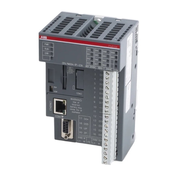
Device Specifications Processor Modules > AC500-eCo ● AC500-S: AC500-S PLCs are designed for safety applications involved in factory or machinery auto- mation area. ● AC500-XC: AC500 (standard) and AC500-S provide devices with -XC extension as a product variant. These variants operate according to their product group and can, in addition, be operated under extreme conditions. - Page 22 Device Specifications Processor Modules > AC500-eCo PM564 CPU PM564-RP-ETH 6DI 24VDC 6DO-R 240VAC 2A 2AI 1AO C0..5 INSERT PUSH STOP SD CARD COM2 COM2 WARNING! Use of incorrect battery may cause fire or explosion 17 NO3 COM1 R3..5 R0..2 24VDC IN 24VDC OUT L+ M FE L+ M 3 LEDs to display the states of the processor module...
- Page 23 Device Specifications Processor Modules > AC500-eCo 1.2.1.1.1 Short Description The processor modules PM55x-xP and PM56x-xP are the central units of AC500-eCo. Their main characteristics are: ● 128 kB (PM554-xP and PM564-xP types) program memory, 512 kB (PM556-xP and PM566- xP types) program memory ●...
- Page 24 Device Specifications Processor Modules > AC500-eCo 1.2.1.1.3 Connections I/O Bus The I/O bus is the I/O data bus for the I/O modules. Through this bus, I/O and diagnosis data are transferred between the processor module and the I/O modules. Up to 10 I/O modules can Ä...
- Page 25 Device Specifications Processor Modules > AC500-eCo According to IEC 60204-1:2016, where control circuits are supplied from an AC source, transformers having separate windings shall be used to separate the power supply from the control supply. Serial interface The serial non-isolated COM1 interface provides communication via RS-485 and is carried out COM1 as a 9-pin D-sub jack.
- Page 26 Device Specifications Processor Modules > AC500-eCo NOTICE! The internal power supply voltage, which is connected to pin 6 of the D-sub connector, must not be short-circuited or connected to any other voltages. Serial interface The optional serial COM2 interface provides communication via RS-485 and is carried out as a COM2 (optional) removable 5-pin terminal with screw connection.
- Page 27 Device Specifications Processor Modules > AC500-eCo Interface Description Not connected Receive Data - Not connected Not connected Shield Cable shield Functional earth The supported protocols and used Ethernet ports can be found in a separate chapter. Communication via Modbus TCP/IP is described in detail in a separate chapter. Electrical Con- nection WARNING!
- Page 28 Device Specifications Processor Modules > AC500-eCo CAUTION! Risk of damaging the processor module and the connected modules! Voltages > 35 VDC (DC variants only) or > 288 VAC (AC variants only) might damage the processor module and the connected modules. Make sure that the supply voltage never exceeds 35 VDC / 288 VAC.
- Page 29 Device Specifications Processor Modules > AC500-eCo Processor Power No. and type No. and type No. and type No. and type module supply of digital of digital out- of analog of analog inputs puts inputs outputs PM55x-T(P), 24 VDC 8 x 24 VDC 6 x 24 VDC, none none...
- Page 30 Device Specifications Processor Modules > AC500-eCo 1.2.1.1.6 Diagnosis The AC500 processor module can display various errors according to the error classes. The fol- lowing error classes are possible. The reaction of the processor module is different for each type of error. Error class Type Description...
- Page 31 Device Specifications Processor Modules > AC500-eCo State Color LED = ON LED = OFF LED flashing Power supply Green Power supply Power supply present missing RUN/STOP Green Processor Processor Fast flashing state module is in module is in (4 Hz): The state RUN state STOP processor...
- Page 32 Device Specifications Processor Modules > AC500-eCo State LEDs Table 6: State LEDs at Ethernet Connector (-ETH models only) Color Flashing Activity Yellow No activity Activity Link Green No link Link 1.2.1.1.8 Technical Data Ä Chapter 2.5.1 “System Data AC500-eCo” The System Data of AC500-eCo apply on page 1192 Only additional details are therefore documented below.
- Page 33 Device Specifications Processor Modules > AC500-eCo Power supply 24 VDC 100 - 240 VAC Max. power dissipation within PM554-TP: 3.0 W PM554-RP-AC: 4.8 W the processor module PM554-TP-ETH: 3.3 W PM564-RP-AC: 4.8 W PM554-RP: 3.5 W PM564-RP-ETH-AC: 5.3 W PM556-TP-ETH: 3.3 W PM564-TP: 3.9 W PM564-TP-ETH: 4.4 W PM564-RP: 4.5 W...
- Page 34 Device Specifications Processor Modules > AC500-eCo Programming languages - Instruction List (IL) - Function Block Diagram (FBD) - Ladder Diagram (LD) - Sequential Function Chart (SFC) - Structured Text (ST) - Continuous Function Chart (CFC) Cycle time for 1000 instructions Binary 0.08 ms Word...
- Page 35 Device Specifications Processor Modules > AC500-eCo Serial interface COM2 (optional) Physical link Non-isolated RS-485 (TA562-RS or TA562- RS-RTC) With 500 VDC galvanically isolated RS-485 (TA569-RS-ISO) Baudrate Configurable from 1.2 to 115.2 kB/s Connection Removable 5-pin terminal block Common mode range Typ.
- Page 36 Device Specifications Processor Modules > AC500-eCo 1.2.1.1.9 Ordering Data Table 7: Processor Modules for AC500-eCo Part No. Description Product Life Cycle Phase *) 1SAP 120 600 R0001 PM554-TP, processor module, 128 kB Active memory, 8 DI, 6 DO-T, 24 VDC, with pluggable I/O terminal blocks 1SAP 120 600 R0071 PM554-TP-ETH, processor module, Active...
- Page 37 Device Specifications Processor Modules > AC500-eCo Table 8: Accessories Part No. Description 1TNE 968 901 Terminal Block TA563-9, 9-pin, screw front, cable side, 6 pieces per R3101 unit 1TNE 968 901 Terminal Block TA563-11, 11-pin, screw front, cable side, 6 pieces per R3102 unit 1TNE 968 901...
- Page 38 Device Specifications Processor Modules > AC500-eCo Terminals of Onboard I/Os for PM55x-T Terminals of Onboard I/Os for PM55x-R and PM55x-R-AC AC500-eCo processor modules are equipped with non-removable terminals. AC500-eCo processor modules are equipped with removable terminal blocks which must be ordered separately. The electrical functionality of both processor module types is identical.
- Page 39 Device Specifications Processor Modules > AC500-eCo 1.2.1.2.2 Functionality Parameter Value Digital inputs 8 (24 VDC), can be used as source inputs or as sink inputs Interrupt inputs 4 (DI0...DI3), configurable Interrupt response time Max. 0.8 ms when input delay is set to 0.1 ms Fast counter 2 (DI0 and DI1), configurable Digital outputs...
- Page 40 Device Specifications Processor Modules > AC500-eCo PM55x-T(P) PM55x-R(P) The assignment of the terminals for PM55x-T(P): Terminal Signal Description C0...7 Input common for digital input signals DI0 to Digital input signal DI0 Digital input signal DI1 Digital input signal DI2 Digital input signal DI3 Digital input signal DI4 Digital input signal DI5 Digital input signal DI6...
- Page 41 Device Specifications Processor Modules > AC500-eCo Terminal Signal Description Digital output signal O1 Digital output signal O2 Digital output signal O3 Digital output signal O4 Digital output signal O5 Process supply voltage UP +24 VDC Process supply voltage ZP 0 VDC The assignment of the terminals for PM55x-R(P): Terminal Signal...
- Page 42 Device Specifications Processor Modules > AC500-eCo NOTICE! Risk of malfunctions in the plant! A ground closure, e. g. caused by a damaged cable insulation, can bridge switches accidentally. Use sink inputs when possible or make sure that, in case of error, there will be no risks to persons or plant.
- Page 43 Device Specifications Processor Modules > AC500-eCo NOTICE! Risk of malfunctions in the plant! The outputs may switch on for a period of 10 to 50 µs if the process supply voltage UP/ZP is switched on. This must be considered in the planning of the application. CAUTION! Risk of damaging the processor module! The outputs are not protected against short circuit and overload.
- Page 44 Device Specifications Processor Modules > AC500-eCo CAUTION! Risk of damaging the processor module! – Never short-circuit or overload the outputs. – Never connect inductive loads without an external suppression against voltage peaks due to inductive kickback. – Never connect voltages > 240 V. All outputs must be fed from the same phase.
- Page 45 Device Specifications Processor Modules > AC500-eCo E1...E Identifier AC500-Display <− Display in 000...063 Class Comp Dev PS501 PLC Browser Class Inter- Device Module Channel Error- Error message Remedy face Identifier Invalid configuration value for Correct frequency PWM channel. Frequency / cycletime for the PWM channel of the 8DI+6DO and 8DI+6DO +2AI+1AO module are common...
- Page 46 Device Specifications Processor Modules > AC500-eCo Parameter Value Input signal range -24 VDC +24 VDC Signal 0 -5 V...+3 V -3 V...+5 V Undefined signal -15 V...- 5 V +5 V...+15 V Signal 1 -30 V...-15 V +15 V...+30 V Ripple with signal 0 Within -5 V...+3 V Within -3 V...+5 V...
- Page 47 Device Specifications Processor Modules > AC500-eCo Parameter Value Way of operation Non-latching type Min. output voltage at signal 1 20 VDC at max. current consumption Output delay (max. at rated load) 0 to 1 50 µs 1 to 0 200 µs Rated protection fuse (per group) 3 A fast Output current...
- Page 48 Device Specifications Processor Modules > AC500-eCo Parameter Value Indication of the output signals 1 yellow LED per channel; the LED is on when the output signal is high (signal 1) and the module is powered through the I/O bus Way of operation Non-latching type Output delay 0 to 1...
- Page 49 Device Specifications Processor Modules > AC500-eCo 1.2.1.3 Onboard I/Os in Processor Module PM56x ● 6 DI 24 VDC ● PM56x-T(P): 6 DO (24 VDC, 0.5 A max. transistor outputs) ● PM56x-R(P) and PM56x-R(P)-AC: 6 DO (24 VDC or 120/240 VAC, 2 A max. relay outputs) ●...
- Page 50 Device Specifications Processor Modules > AC500-eCo Processor Power No. and type No. and type No. and type No. and type module supply of digital of digital out- of analog of analog inputs puts inputs outputs PM56x-T(P), 24 VDC 6 x 24 VDC *) 6 x 24 VDC, 2 x voltage *) 1 x voltage or PM56x-T(P)-...
- Page 51 Device Specifications Processor Modules > AC500-eCo 1.2.1.3.3 Electrical Connection NOTICE! Risk of damaging the PLC modules! The PLC modules must not be removed while the plant is connected to a power supply. Make sure that all voltage sources (supply and process voltage) are switched off before you –...
- Page 52 Device Specifications Processor Modules > AC500-eCo PM56x-T(P) PM56x-R(P) Assignment of Terminal Signal Description the Terminals C0...5 Input common for digital input signals DI0 to DI5 for PM56x-T(P) Digital input signal DI0 Digital input signal DI1 Digital input signal DI2 Digital input signal DI3 Digital input signal DI4 Digital input signal DI5 Analog voltage input signal AI0...
- Page 53 Device Specifications Processor Modules > AC500-eCo Terminal Signal Description Digital output signal O3 Digital output signal O4 Digital output signal O5 Process supply voltage UP +24 VDC Process supply voltage ZP 0 VDC Assignment of Terminal Signal Description the Terminals C0...5 Input common for digital input signals DI0 to DI5 for PM56x-R(P)
- Page 54 Device Specifications Processor Modules > AC500-eCo *) The M-terminal of the onboard I/Os is inter- *) The M-terminal of the Onboard I/Os is inter- nally connected to the M-terminal of the pro- nally connected to the M-terminal of the pro- cessor-module supply voltage cessor-module supply voltage Electrical connection of digital inputs (sink...
- Page 55 Device Specifications Processor Modules > AC500-eCo NOTICE! Risk of malfunctions in the plant! The outputs may switch on for a period of 10 to 50 µs if the process supply voltage UP/ZP is switched on. This must be considered in the planning of the application. CAUTION! Risk of damaging the processor module! The outputs are not protected against short circuit and overload.
- Page 56 Device Specifications Processor Modules > AC500-eCo CAUTION! Risk of damaging the processor module! – Never short-circuit or overload the outputs. – Never connect inductive loads without an external suppression against voltage peaks due to inductive kickback. – Never connect voltages > 240 V. All outputs must be fed from the same phase.
- Page 57 Device Specifications Processor Modules > AC500-eCo Connection of analog actuator (voltage) Connection of analog actuator (current) 1.2.1.3.4 Internal Data Exchange Parameter Value Digital inputs (bytes) Digital outputs (bytes) Analog inputs (bytes) Analog outputs (bytes) 1.2.1.3.5 I/O Configuration The configuration data of the onboard I/Os is stored in the processor module PM56x. 1.2.1.3.6 Parameterization For information about parameterization, refer to the description for onboard I/Os for processor...
- Page 58 Device Specifications Processor Modules > AC500-eCo E1...E4 Identifier AC500- <− Display in Display 000...063 Class Comp PS501 Browser Class Inter- Device Module Channel Error- Error message Remedy face Identifier Invalid configuration of Correct onboard I/O module, e. PLC con- g. 2 input channels are figuration configured as fast counter and interrupt...
- Page 59 Device Specifications Processor Modules > AC500-eCo 1.2.1.3.8 Displays Status Color LED = ON LED = OFF DI0...DI5 Digital input yellow Input is ON Input is OFF DO0...DO5 Digital output yellow Output is ON Output is OFF AI0, AI1*) Analog input yellow Input is ON Input is OFF...
- Page 60 Device Specifications Processor Modules > AC500-eCo Range 0 V...+10 V 0 mA...20 mA Digital value Decimal Hex. 0.00 0.00 0000 Output value too FFE0 low or underflow -6912 E500 0.00 -32768 8000 Range 4 mA...20 mA Digital value Decimal Hex. Overflow 22.80 32767...
- Page 61 Device Specifications Processor Modules > AC500-eCo Parameter Value Signal 0 -5 V...+3 V -3 V...+5 V Undefined signal -15 V...- 5 V +5 V...+15 V Signal 1 -30 V...-15 V +15 V...+30 V Ripple with signal 0 Within -5 V...+3 V Within -3 V...+5 V Ripple with signal 1 Within -30 V...-15 V Within +15 V...+30...
- Page 62 Device Specifications Processor Modules > AC500-eCo Parameter Value Min. output voltage at signal 1 20 VDC at max. current consumption Output delay (max. at rated load) 0 to 1 50 µs 1 to 0 200 µs Rated protection fuse (per group) 3 A fast Output current Rated current per channel (max.)
- Page 63 Device Specifications Processor Modules > AC500-eCo Parameter Value Indication of the output signals 1 yellow LED per channel; the LED is on when the output signal is high (signal 1) and the module is powered through the I/O bus Way of operation Non-latching type Output delay 0 to 1...
- Page 64 Device Specifications Processor Modules > AC500-eCo Technical Data of the Analog Inputs Parameter Value Number of channels per module 2 voltage inputs Distribution of channels into groups 1 group for 2 channels Galvanic isolation None Power Supply Voltage Via the L+ and the M terminal of the pro- cessor-module power supply Resolution Voltage 0 VDC...10 VDC: 10 bits...
-
Page 65: Ac500 (Standard)
Device Specifications Processor Modules > AC500 (Standard) Parameter Value Output load ability as voltage output +2 mA max. Accuracy for current and voltage output Typical (25 °C) ±1 % of full-scale Worst case (at 0 °C...60 °C or EMC distur- ±2.5 % of full-scale bances) Relationship between input signal and hex... - Page 66 Device Specifications Processor Modules > AC500 (Standard) 6x 7-segment state displays with background 14 Interface for FieldBusPlug lighting 15 Power supply (5-pin terminal block, removable) "Triangle" displays for "item" 16 Serial interface COM1 (9-pin terminal block, remov- "Square" displays for "state" able) 3 state LEDs 17 PM5xy-ETH and PM5xy-ARCNET: D-sub 9 for serial...
- Page 67 Device Specifications Processor Modules > AC500 (Standard) The terminal base type depends on the number of communication modules which are used together with the processor module and on the processor module's network interface type (1x Ethernet, 2x Ethernet or ARCNET). Each processor module can operate multiple communication modules through its communica- tion module interface (defined by the terminal base).
- Page 68 Device Specifications Processor Modules > AC500 (Standard) 1.2.2.1.2 Assortment Module Program Cycle Time Network Interface Other Inter- Suitable and Data for 1 Instruc- faces Terminal Base Ethernet ARCNET Memory tion PM572 128 kB Binary: min. TB5x1-ETH 0.06 µs PM573-ETH 512 kB Onboard TB5x1-ETH Word: min.
- Page 69 Device Specifications Processor Modules > AC500 (Standard) 1.2.2.1.3 Connections All terminals for electrical connection are available on the terminal base. For information on con- nection and available interfaces see the descriptions for Ä Chapter 1.1.1 “TB51x-TB54x” on page 4 ● TB511 Ä...
- Page 70 Device Specifications Processor Modules > AC500 (Standard) 1.2.2.1.5 LEDs, Display and Function Keys on the Front Panel Detailed information on using the LEDs, display and the function keys such as startup procedure and error coding is described in the System Technology sec- tion Display.
- Page 71 Device Specifications Processor Modules > AC500 (Standard) Parameter Value PM59x: 90 mA PM59x-ETH: 150 mA PM59x-2ETH: 150 mA PM59x-ARCNET: 150 mA Fuse melting integral at 24 VDC Min. 1 A²s Ä Chapter 2.4.5.2 “Dimensioning of the Fuses” on page 1191 Max.
- Page 72 Device Specifications Processor Modules > AC500 (Standard) Detailed Data Table 10: PM57x Processor Module PM572 PM573-ETH Program memory flash EPROM 128 kB 512 kB and RAM Data memory, integrated 128 kB, incl. 12 kB 512 kB, incl. 288 kB buffered buffered Expandable memory None...
- Page 73 Device Specifications Processor Modules > AC500 (Standard) Processor Module PM572 PM573-ETH Physical link Configurable for RS-232 or RS-485 (from 0.3 to 187.5 kB/s) pluggable terminal block, spring connection for pro- Connection gramming, as Modbus (master/slave), as serial ASCI communication, as CS31 Master Usage Serial interface COM2 (not for PM5xy-2ETH models): Physical link...
- Page 74 Device Specifications Processor Modules > AC500 (Standard) Processor Module PM582 PM583-ETH PM585-ETH Program storage Firmware update Cycle time for 1 instruction: Binary Min. 0.05 µs Min. 0.004 µs Word Min. 0.06 µs Min. 0.008 µs Floating point Min. 0.50 µs Min.
- Page 75 Device Specifications Processor Modules > AC500 (Standard) Processor Module PM582 PM583-ETH PM585-ETH ETH = Ethernet ETH onboard with web server, SNTP and IEC60870-5-104 RJ45 protocol ARCNET = ARCNET BNC Number of external communication modules Up to 4 communication modules like PRO- FIBUS DP, Ethernet, CANopen.
- Page 76 Device Specifications Processor Modules > AC500 (Standard) Processor Module PM59x-ETH PM59x- PM59x-ETH ARCNET PM59x-2ETH Binary Min. 0.002 µs Min. 0.002 µs Min. 0.002 µs Word Min. 0.004 µs Min. 0.004 µs Min. 0.004 µs Floating point Min. 0.004 µs Min. 0.004 µs Min.
- Page 77 Device Specifications Processor Modules > AC500 (Standard) Processor Module PM59x-ETH PM59x- PM59x-ETH ARCNET PM59x-2ETH ETH = Ethernet ARCNET ETH onboard with Web- RJ45 ARCNET server, SNTP ARCNET = ARCNET ARCNET IEC60870-5-10 4 protocol Number of external communication mod- Up to 4 communication modules like PROFIBUS ules DP, Ethernet, CANopen.
- Page 78 Device Specifications Processor Modules > AC500 (Standard) 1.2.2.1.7 Ordering Data Processor Mod- Part No. Description Product Life Cycle Phase *) ules for AC500 1SAP 130 200 R0200 PM572, processor module, memory Active (Standard) V2 128 kB, 24 VDC, memory card slot, Products interfaces 2x RS-232/485 (programming, Modbus/CS31),...
- Page 79 Device Specifications Processor Modules > AC500 (Standard) Part No. Description Product Life Cycle Phase *) 1SAP 150 000 R0271 PM590-ETH, processor module, Active memory 2 MB, 24 VDC, memory card slot, interfaces 2x RS-232/485 (programming, Modbus/CS31), 1x FBP, display, onboard Ethernet TCP/IP with web server, SNTP, IEC60870-5-104 protocols 1SAP 150 100 R0271 PM591-ETH, processor module,...
- Page 80 Device Specifications Processor Modules > AC500 (Standard) Processor module PM591-2ETH can only be used with TB523-2ETH. Processor modules PM57x-ETH(-XC), PM58x-ETH(-XC) and PM59x-ETH(-XC) with ordering No. 1SAPxxxxxxR0271 can only be used with terminal bases TB5x1-ETH(-XC) with ordering No. 1SAPxxxxxxR0270. 1.2.2.2 PM595 ●...
- Page 81 Device Specifications Processor Modules > AC500 (Standard) 1.2.2.2.1 Short Description The processor module is a central unit for AC500 with high performance. Each processor module can operate up to 2 communication modules via its communication module interface. The communication modules are mounted on the left side of the processor module.
- Page 82 Device Specifications Processor Modules > AC500 (Standard) For PM595 only: For EtherCAT and PROFINET support make sure the following firmware is installed: – PROFINET: V 2.8.1.2 or newer – EtherCAT: V 4.2.23 (2) or newer To update the Firmware of PM595, please follow the instructions in the chapter Firmware update.
- Page 83 Device Specifications Processor Modules > AC500 (Standard) Power Supply Pin assignment The supply voltage of 24 VDC is connected to a removable 5-pin terminal block. L+/M exist twice. It is therefore possible to feed e.g. external sensors (up to 8 A max. with 1.5 mm con- ductor) via these terminals.
- Page 84 Device Specifications Processor Modules > AC500 (Standard) NOTICE! Risk of damaging the terminal base! Excessive current might damage the clamp and terminal base. Make sure that the current flowing through the removable clamps never exceeds 8 A (with 1.5 mm conductor).
- Page 85 Device Specifications Processor Modules > AC500 (Standard) Pin assignment Serial Signal Interface Description Interface Functional earth RS-232 Transmit data Output RxD/TxD-P RS-485 Receive/Transmit Positive RS-232 Request to send Output SGND Signal ground 0 V supply out +5 V 5 V supply out RS-232 Receive data Input...
- Page 86 Device Specifications Processor Modules > AC500 (Standard) MAC Addresses The MAC addresses of the network interfaces of the PM595-4ETH are printed on the label in the following way: MAC ETH1 MAC ETH2 MAC ETH3 MAC ETH4 The figure below shows the assignment of the MAC addresses to the corresponding interface. Fig.
- Page 87 Device Specifications Processor Modules > AC500 (Standard) The memory card can be used ● to read and write user files ● for firmware updates Detailed information can be found in the System Technology chapter. AC500 processor modules can be operated with and without memory cards. The processor module uses a standard file system (FAT;...
- Page 88 Device Specifications Processor Modules > AC500 (Standard) Color Status Description Green Power supply available Blinking Power supply not available or defec- tive hardware Green Processor module is in RUN mode Blinking Processor module is in STOP mode Red/green An error has occurred Blinking Flashing fast (4 Hz): Indicates together with RUN a firmware update...
- Page 89 Device Specifications Processor Modules > AC500 (Standard) Button Description RESET If pressed during power-on: Enter serial download of firmware. This is signalized by blinking of the RUN LED with a frequency of 1 Hz. If pressed during normal operation: reserved for future implementation. If pressed during power-on: Bootproject will not be loaded.
- Page 90 Device Specifications Processor Modules > AC500 (Standard) Detailed data Parameter Value Flash memory for boot projects, symbols and web 32768 kB pages SDRAM for user program 16384 kB SDRAM for user data 16384 kB Expandable memory None Integrated mass storage memory 4 GB non rotating flashdisk Pluggable memory card for: User data storage...
- Page 91 Device Specifications Processor Modules > AC500 (Standard) Parameter Value LCD display Optional Buttons and switches 1 button for Reset (Reserved) 1 Button (Reserved) 1 Switch for RUN/STOP 1.2.2.2.7 Ordering Data Part No. Description Product Life Cycle Phase *) 1SAP 155 500 R0279 PM595-4ETH-F, processor module, Active user progr./data memory 16 MB / 16 MB,...
-
Page 92: Communication Modules (Ac500 Standard)
Device Specifications Communication Modules (AC500 Standard) > Overview 1.3 Communication Modules (AC500 Standard) 1.3.1 Overview AC500 communication modules are required for ● a connection to standard field bus systems and ● for integration into existing networks. AC500 communication modules ● enable communication on different field buses. - Page 93 Device Specifications Communication Modules (AC500 Standard) > Overview WARNING! Removal/Insertion under power The devices are not designed for removal or insertion under power. Because of unforeseeable consequences, it is not allowed to plug or unplug devices with the power being ON. Make sure that all voltage sources (supply and process voltage) are switched off before you –...
- Page 94 Device Specifications Communication Modules (AC500 Standard) > Overview 1.3.1.1 Technical Data (Overview) CM574- CM574- CM579 CM582-DP CM598-CN CM589- CM597-ETH RCOM PNIO(-4) CM592-DP CM588-CN ETHC CM579-PNIO Field bus RCOM/ Serial EtherC PROFIBUS CANopen PROFINET 2 x Ethernet RCOM+ (ASCII/ Modbus) Transmission 2.4 kBit/s 9.6 kBit/s 9.6 kBit/s to...
-
Page 95: Cm574-Rcom For Rcom/Rcom
Device Specifications Communication Modules (AC500 Standard) > CM574-RCOM for RCOM/RCOM+ 1.3.2 CM574-RCOM for RCOM/RCOM+ 5 LEDs for state display Label 2 interfaces: 1x RCOM protocol interface, 1x CONSOLE 1.3.2.1 Purpose Communication module CM574-RCOM is equipped with 2 serial interfaces (RCOM protocol communication and Console) which provide the remote protocol RCOM/RCOM+. - Page 96 Switch between two protocols (Online access, Modbus, ASCII, SysLibCom) using the block COM_SET_PROT CS31 bus CS31 bus master RCOM/RCOM+ ABB remote protocol RCOM or RCOM+ (only available as sepa- rate communication module CM574-RCOM) COM2 Online access Online access for IEC 61131-3 programming with serial driver...
- Page 97 Device Specifications Communication Modules (AC500 Standard) > CM574-RCOM for RCOM/RCOM+ Bus line Remarks Commonly used telephone cables with PE insulation and a core diameter of > 0.8 mm are usually sufficient. Cables with PVC core insulation and core diameter of 0.8 mm can be used up to a length of approx.
- Page 98 Device Specifications Communication Modules (AC500 Standard) > CM574-RCOM for RCOM/RCOM+ Color State Description Flashes Protocol error occurred cyclically No communication Yellow Flashes Traffic detected Error No error 1.3.2.4 Technical Data Ä Chapter 2.6.1 “System Data AC500” on page 1248 are The System Data of AC500 and S500 valid for standard version.
- Page 99 Device Specifications Communication Modules (AC500 Standard) > CM574-RCOM for RCOM/RCOM+ Table 19: Technical Data of the Interfaces Parameter Value Serial interface standard EIA RS-232 or EIA RS-485 Interface connector Pluggable 9-pin terminal block Potential separation Yes, from the CPU, 500 VDC Serial interface parameters Protocol interface configurable via PLC config- uration.
-
Page 100: Cm574-Rs With 2 Serial Interfaces
Device Specifications Communication Modules (AC500 Standard) > CM574-RS with 2 Serial Interfaces 1.3.3 CM574-RS with 2 Serial Interfaces 5 LEDs for state display 2 rotary switches for address setting Label 2 serial communication interfaces 1.3.3.1 Purpose Communication module CM574-RS is equipped with 2 serial interfaces (COM1 and COM2) which can be used as programming interface or for communication e.g. - Page 101 Switch between two protocols (Online access, Modbus, ASCII, SysLibCom) using the block COM_SET_PROT CS31 bus CS31 bus master RCOM/RCOM+ ABB remote protocol RCOM or RCOM+ (only available as sepa- rate communication module CM574-RCOM) COM2 Online access Online access for IEC 61131-3 programming with serial driver...
- Page 102 Device Specifications Communication Modules (AC500 Standard) > CM574-RS with 2 Serial Interfaces Bus line Remarks Commonly used telephone cables with PE insulation and a core diameter of > 0.8 mm are usually sufficient. Cables with PVC core insulation and core diameter of 0.8 mm can be used up to a length of approx.
- Page 103 Device Specifications Communication Modules (AC500 Standard) > CM574-RS with 2 Serial Interfaces 1.3.3.4 Technical Data Ä Chapter 2.6.1 “System Data AC500” on page 1248 are The System Data of AC500 and S500 valid for standard version. Ä Chapter 2.7.1 “System Data AC500-XC” on page 1309 are The System Data of AC500-XC valid for the XC version.
-
Page 104: Canopen
Device Specifications Communication Modules (AC500 Standard) > CANopen 1.3.3.5 Ordering Data Part No. Description Product Life Cycle Phase *) 1SAP 170 400 R0201 CM574-RS, communication module, Active 2x serial RS232/485, free configurable serial interface module *) For planning and commissioning of new installations use modules in Active status only. - Page 105 Device Specifications Communication Modules (AC500 Standard) > CANopen 1.3.4.1.1 Purpose Communication module CM588-CN enables communication via the CANopen field bus. Ä Chapter 1.3.4.1 “CM588-CN - CANopen Slave” on page 104 is a slave in a CAN- CM588-CN open network. It is connected to the processor module via an internal communication bus. CM588-CN allows communicating of multiple CPUs in a CANopen network.
- Page 106 Device Specifications Communication Modules (AC500 Standard) > CANopen Types of Bus For CANopen, only bus cables with characteristics as recommended in ISO 11898 are to be Cables used. The requirements for the bus cables depend on the length of the bus segment. Regarding this, the following recommendations are given by ISO 11898: Length of seg- Bus cable (shielded, twisted pair)
- Page 107 Device Specifications Communication Modules (AC500 Standard) > CANopen +24 V Fig. 8: DeviceNet interface, bus terminating resistors connected to the line ends DeviceNet power supply COMBICON connection, DeviceNet interface Data lines, twisted pair cables black white blue bare The earthing of the shield should take place at the switch-gear. Please refer to Ä...
- Page 108 Device Specifications Communication Modules (AC500 Standard) > CANopen 1.3.4.1.3 State LEDs The state of the CANopen communication module is displayed by means of 5 state LEDs. Table 21: Meaning of the diagnosis LEDs Color State Description Green ON (light) Power supply available OFF (dark) Power supply not available or defective hardware...
- Page 109 Device Specifications Communication Modules (AC500 Standard) > CANopen Parameter Value Ä Chapter 1.2.2.1 Usable CPUs PM57x, PM58x, PM59x “PM57x (-y), PM58x (-y) and PM59x (-y)” on page 65 Usable terminal bases All TB5xx Ä Chapter 1.1.1 “TB51x-TB54x” on page 4 Bus connection Pluggable connector COMBICON, 2x5-pin Internal power supply...
- Page 110 Device Specifications Communication Modules (AC500 Standard) > CANopen 1.3.4.2 CM598-CN - CANopen Master ● CANopen master 1 Mbit/s ● XC version for use in extreme ambient conditions available 5 LEDs for state display Label Communication interface, 5-pin, Combicon, male, removable plug with spring terminals Sign for XC version 1.3.4.2.1 Purpose...
- Page 111 Device Specifications Communication Modules (AC500 Standard) > CANopen Transmission protocol CANopen (CAN), 1 Mbaud max. Transfer rate (baud rate) 10 kbit/s, 20 kbit/s, 50 kbit/s, 100 kbit/s, 125 kbit/s, 250 kbit/s, 500 kbit/s, 800 kbit/s and 1 Mbit/s, The CANopen connector has the following pin assignment: Pin Assignment Interface Signal...
- Page 112 Device Specifications Communication Modules (AC500 Standard) > CANopen Length of seg- Bus cable (shielded, twisted pair) Max. baud rate ment [m] [kbit/s] Conductor Line resistance Wave impe- cross section [W/km] dance [W] [mm²] 0...40 0.25...0.34 / 1000 at 40 m AWG23, AWG22 40...300 0.34...0.60 /...
- Page 113 Device Specifications Communication Modules (AC500 Standard) > CANopen +24 V Fig. 10: DeviceNet interface, bus terminating resistors connected to the line ends DeviceNet power supply COMBICON connection, DeviceNet interface Data lines, twisted pair cables black white blue bare The earthing of the shield should take place at the switch-gear. Please refer to Ä...
- Page 114 Device Specifications Communication Modules (AC500 Standard) > CANopen 1.3.4.2.3 State LEDs Table 22: Meaning of the diagnosis LEDs Color State Description Green ON (light) Power supply available OFF (dark) Power supply not available or defective hardware Yellow ON Boot procedure Blinking Boot failure Green...
- Page 115 Device Specifications Communication Modules (AC500 Standard) > CANopen Parameter Value Protocol CANopen Master, CAN2A, CAN2B Transmission rate 10 kbit/s to 1 Mbit/s Ambient temperature see: Ä Chapter 2.6.1 “System System data AC500 Data AC500” on page 1248 Ä Chapter 2.7.1 System Data AC500 XC “System Data AC500-XC”...
-
Page 116: Ethercat
Device Specifications Communication Modules (AC500 Standard) > EtherCAT 1.3.5 EtherCAT 1.3.5.1 CM579-ETHCAT - EtherCAT Master 5 LEDs for state display 2 rotary switches for address setting (not used) Label 2 communication interfaces RJ45 (ETHCAT1 and ETHCAT2) 1.3.5.1.1 Intended Purpose Communication module CM579-ETHCAT is for EtherCAT communication. The comunication module is configured via the dual-port memory by means of a system config- urator. - Page 117 Device Specifications Communication Modules (AC500 Standard) > EtherCAT Table 23: Pin assignment RJ45 jack: Interface Signal Description TxD+ Transmit data + TxD- Transmit data - RxD+ Receive data + not used not used RxD- Receive data - not used not used Shield Cable shield Functional earth...
- Page 118 Device Specifications Communication Modules (AC500 Standard) > EtherCAT 1.3.5.1.3 State LEDs The EtherCAT state is shown by the EtherCAT communication module's LEDs. Some LEDs are two-colored. Table 24: Meaning of the diagnosis LEDs Color State Description Green Power supply available Blinking Power supply not available or defective hardware...
- Page 119 Device Specifications Communication Modules (AC500 Standard) > EtherCAT 1.3.5.1.4 Technical Data Ä Chapter 2.6.1 “System Data AC500” on page 1248 are The System Data of AC500 and S500 valid for standard version. Ä Chapter 2.7.1 “System Data AC500-XC” on page 1309 are The System Data of AC500-XC valid for the XC version.
-
Page 120: Ethernet
Device Specifications Communication Modules (AC500 Standard) > Ethernet 1.3.5.1.5 Ordering Data Part No. Description Product Life Cycle Phase *) 1SAP 170 902 R0101 CM579-ETHCAT, EtherCAT Active communication module *) For planning and commissioning of new installations use modules in Active status only. - Page 121 Device Specifications Communication Modules (AC500 Standard) > Ethernet 1.3.6.1.1 Purpose The communication module provides communication via the Ethernet bus. Ethernet connection can be established directly to the communication module, an additional switch is not necessary. The Ethernet communication module is an intelligent 100-base-T-Ethernet communication inter- face based on the highly integrated netX100 micro-controller.
- Page 122 Device Specifications Communication Modules (AC500 Standard) > Ethernet 1.3.6.1.3 State LEDs The Ethernet state is shown by the Ethernet communication module's LEDs. Table 27: Meaning of the diagnosis LEDs Color State Description Green Power supply available Power supply not available or defective hardware Yellow On Boot procedure...
- Page 123 Device Specifications Communication Modules (AC500 Standard) > Ethernet 1.3.6.1.4 Technical Data Ä Chapter 2.6.1 “System Data AC500” on page 1248 are The System Data of AC500 and S500 valid for standard version. Ä Chapter 2.7.1 “System Data AC500-XC” on page 1309 are The System Data of AC500-XC valid for the XC version.
-
Page 124: Profibus
Device Specifications Communication Modules (AC500 Standard) > PROFIBUS 1.3.6.1.5 Ordering Data Part No. Description Product Life Cycle Phase *) 1SAP 173 700 R0001 CM597-ETH, communication module Active Ethernet TCP/IP with integrated 2-port switch 1SAP 373 700 R0001 CM597-ETH-XC, Active communication module Ethernet TCP/IP with integrated 2-port switch, XC version *) For planning and commissioning of new installations use modules in Active... - Page 125 Device Specifications Communication Modules (AC500 Standard) > PROFIBUS 5 LEDs for state display Label Communication interface PROFIBUS DP D-sub, 9-pin, female Sign for XC version 1.3.7.1.1 Purpose Communication module CM582-DP enables communication over the PROFIBUS DP field bus. For use in extreme ambient conditions (e.g. wider temperature and humidity range), a special XC version of the device is available.
- Page 126 Device Specifications Communication Modules (AC500 Standard) > PROFIBUS 1.3.7.1.2 Electrical Connection Field Bus Interface The PROFIBUS DP connector (9-pin, female) has the following pin assignment: Signal Description Not connected Not connected RxD/TxD-P Receive/Transmit positive CNTR-P Control signal for repeater, positive DGND Reference potential for data exchange and +5 Vl +5 V (power supply for the bus terminating resistors)
- Page 127 Device Specifications Communication Modules (AC500 Standard) > PROFIBUS 1.3.7.1.3 State LEDs The PROFIBUS state is shown by state LEDs. Table 30: Meaning of the diagnosis LEDs Color State Description Green ON (light) Power supply available. OFF (dark) Power supply not available or defective hardware Yellow ON Boot procedure...
- Page 128 Device Specifications Communication Modules (AC500 Standard) > PROFIBUS Parameter Value Ä Chapter 1.1.1 “TB51x-TB54x” Usable terminal bases All TB5xx on page 4 Current consumption from 24 VDC power Typ. 65 mA supply at the terminal base of the CPU Internal power supply Through the communication module interface of the terminal base Maximum number of cyclic input data...
- Page 129 Device Specifications Communication Modules (AC500 Standard) > PROFIBUS 5 LEDs for state display Label Communication interface PROFIBUS DP D-sub, 9-pin, female Sign for XC version 1.3.7.2.1 Purpose Communication module CM592-DP enables communication over the PROFIBUS DP field bus. For use in extreme ambient conditions (e.g. wider temperature and humidity range), a special XC version of the device is available.
- Page 130 Device Specifications Communication Modules (AC500 Standard) > PROFIBUS 1.3.7.2.2 Electrical Connection Field Bus Interface The PROFIBUS DP connector (9-pin, female) has the following pin assignment: Signal Description Not connected Not connected RxD/TxD-P Receive/Transmit positive CNTR-P Control signal for repeater, positive DGND Reference potential for data exchange and +5 Vl +5 V (power supply for the bus terminating resistors)
- Page 131 Device Specifications Communication Modules (AC500 Standard) > PROFIBUS 1.3.7.2.3 State LEDs The PROFIBUS state is shown by state LEDs. Table 32: Meaning of the diagnosis LEDs Color State Description Green ON (light) Power supply available OFF (dark) Power supply not available or defective hardware Yellow ON Boot procedure...
- Page 132 Device Specifications Communication Modules (AC500 Standard) > PROFIBUS Parameter Value State indication By 5 LEDs PWR, RDY, RUN, STA, ERR Ä Chapter 1.2.2.1 Usable CPUs PM57x, PM58x, PM59x “PM57x (-y), PM58x (-y) and PM59x (-y)” on page 65 Usable terminal bases All TB5xx Ä...
- Page 133 Device Specifications Communication Modules (AC500 Standard) > PROFIBUS *) For planning and commissioning of new installations use modules in Active status only. 1.3.7.3 PROFIBUS Connection Details Attachment 9-pin D-sub connector, male Plug for the Bus Cable Parameter Value Fastening torque 0.4 Nm Assignment Signal...
-
Page 134: Profinet
Device Specifications Communication Modules (AC500 Standard) > PROFINET Baud Rate Maximum Cable Length 9.6 / 19.2 / 93.75 kBaud 1200 m 187.5 kBaud 1000 m 500 kBaud 400 m 1.5 MBaud 200 m 3 MBaud to 12 MBaud 100 m Branch lines are generally permissible for baud rates of up to 1500 kbit/s. - Page 135 Device Specifications Communication Modules (AC500 Standard) > PROFINET 5 LEDs for state display 2 rotary switches for address setting (not used) Label 2 communication interfaces RJ45 (PNIO1 and PNIO2) Sign for XC version 1.3.8.1.1 Intended Purpose The communication module is for PROFINET RT communication. The PROFINET communication module includes an internal Ethernet switch.
- Page 136 Device Specifications Communication Modules (AC500 Standard) > PROFINET 1.3.8.1.2 Functionality Parameter Value Protocol PROFINET I/O RT Usable CPUs PM57x, PM58x, PM59x Ä Chapter 1.2.2.1 “PM57x (-y), PM58x (-y) and PM59x (-y)” on page 65 PM56xx Ä Chapter 1.1.1 “TB51x-TB54x” Usable terminal bases All TB5xx on page 4 All TB56xx (not TB5600)
- Page 137 Device Specifications Communication Modules (AC500 Standard) > PROFINET 1.3.8.1.4 State LEDs The PROFINET state is shown by the state LEDs. Table 34: Meaning of the diagnosis LEDs Color State Description Green Power supply available Blinking Power supply not available or defective hardware Yellow On Boot procedure...
- Page 138 Device Specifications Communication Modules (AC500 Standard) > PROFINET Color State Description Blinking Device sends/receives frames 1.3.8.1.5 Technical Data Ä Chapter 2.6.1 “System Data AC500” on page 1248 are The System Data of AC500 and S500 valid for standard version. The System Data of AC500-XC Ä...
- Page 139 Device Specifications Communication Modules (AC500 Standard) > PROFINET Parameter Value Total quantity of input and output data CM579-PNIO < FW 2.4.8.0 1024 bytes input and output data per IO device but in total 3072 bytes input output data CM579-PNIO = FW 2.4.8.0 1024 bytes input and output data per IO device but in total 4096 bytes input output data...
- Page 140 Device Specifications Communication Modules (AC500 Standard) > PROFINET 5 LEDs for state display 2 rotary switches for setting the I/O device identifier Label 2 communication interfaces RJ45 (PNIO1 and PNIO2) Sign for XC version The communication module is for PROFINET RT communication. The PROFINET communication module includes an internal Ethernet switch.
- Page 141 Device Specifications Communication Modules (AC500 Standard) > PROFINET 1.3.8.2.1 Functionality Parameter Value Protocol PROFINET I/O RT Usable CPUs PM57x, PM58x, PM59x Ä Chapter 1.2.2.1 “PM57x (-y), PM58x (-y) and PM59x (-y)” on page 65 PM56xx Ä Chapter 1.1.1 “TB51x-TB54x” Usable terminal bases All TB5xx on page 4 All TB56xx (not TB5600)
- Page 142 Device Specifications Communication Modules (AC500 Standard) > PROFINET 1.3.8.2.4 State LEDs The PROFINET state is shown by the state LEDs. Table 37: Meaning of the diagnosis LEDs Color State Description Green Power supply available Blinking Power supply not available or defective hardware Yellow On Boot procedure...
- Page 143 Device Specifications Communication Modules (AC500 Standard) > PROFINET Color State Description Blinking Device sends/receives frames 1.3.8.2.5 Technical Data Ä Chapter 2.6.1 “System Data AC500” on page 1248 are The System Data of AC500 and S500 valid for standard version. Ä Chapter 2.7.1 “System Data AC500-XC” on page 1309 are The System Data of AC500-XC valid for the XC version.
- Page 144 Device Specifications Communication Modules (AC500 Standard) > PROFINET Parameter Value Acyclic services PNIO read / write CM589-PNIO < FW 1.4.0: max. 1024 bytes CM589-PNIO ≥ FW 1.4.0: max. 8096 bytes CM589-PNIO-4: max. 8096 bytes Total quantity of input and output data CM589-PNIO <...
-
Page 145: Terminal Units (Ac500 Standard)
Device Specifications Terminal Units (AC500 Standard) > TU507-ETH and TU508-ETH for Ethernet Communication Interface Modules 1.4 Terminal Units (AC500 Standard) Hot swap Preconditions for hot swapping I/O modules: – Hot-swappable terminal units have the appendix TU5xx-H. – I/O modules as of index F0. –... - Page 146 Device Specifications Terminal Units (AC500 Standard) > TU507-ETH and TU508-ETH for Ethernet Communication Interface Modules I/O bus (10 pins, female) to electrically connect the first terminal unit Plug (1x 50 pins and 2x 57 pins) to electrically connect the inserted Ethernet communication interface module With a screwdriver, inserted in this place, the terminal unit and the adjacent terminal unit can be shoved from each other...
- Page 147 Device Specifications Terminal Units (AC500 Standard) > TU507-ETH and TU508-ETH for Ethernet Communication Interface Modules XC Version XC = eXtreme Conditions Extreme conditions Terminal units for use in extreme ambient conditions have no sign for XC version. The figure 4 in the Part No. 1SAP4... (label) identifies the XC version. Terminals Screw terminals Spring terminals...
- Page 148 Device Specifications Terminal Units (AC500 Standard) > TU507-ETH and TU508-ETH for Ethernet Communication Interface Modules NOTICE! Risk of corrosion! Unused connectors and slots may corrode if XC devices are used in salt-mist environments. Protect unused connectors and slots with TA535 protective caps for XC devices Ä...
-
Page 149: Tu509 And Tu510 For Communication Interface Modules
Device Specifications Terminal Units (AC500 Standard) > TU509 and TU510 for Communication Interface Modules 1.4.1.2 Ordering Data Part No. Description Product Life Cycle Phase *) 1SAP 214 200 R0001 TU507-ETH, Ethernet terminal unit, Active 24 VDC, screw terminals 1SAP 214 000 R0001 TU508-ETH, Ethernet terminal unit, Active 24 VDC, spring terminals 1SAP 414 000 R0001 TU508-ETH-XC, Ethernet terminal... - Page 150 Device Specifications Terminal Units (AC500 Standard) > TU509 and TU510 for Communication Interface Modules I/O bus (10 pins, female) to electrically connect the first terminal unit Plug (1x 50 pins and 2x 57 pins) to electrically connect the inserted communication interface module With a screwdriver, inserted in this place, the terminal unit and the adjacent terminal unit can be shoved from each other...
- Page 151 Device Specifications Terminal Units (AC500 Standard) > TU509 and TU510 for Communication Interface Modules XC Version XC = eXtreme Conditions Extreme conditions Terminal units for use in extreme ambient conditions have no sign for XC version. The figure 4 in the Part No. 1SAP4... (label) identifies the XC version. Terminals Screw terminals Spring terminals...
- Page 152 Device Specifications Terminal Units (AC500 Standard) > TU509 and TU510 for Communication Interface Modules NOTICE! Risk of corrosion! Unused connectors and slots may corrode if XC devices are used in salt-mist environments. Protect unused connectors and slots with TA535 protective caps for XC devices Ä...
-
Page 153: Tu515, Tu516, Tu516-H And Tu542 For I/O Modules
Device Specifications Terminal Units (AC500 Standard) > TU515, TU516, TU516-H and TU542 for I/O Modules *) For planning and commissioning of new installations use modules in Active status only. 1.4.3 TU515, TU516, TU516-H and TU542 for I/O Modules ● TU515, I/O terminal unit, 24 VDC, screw terminals ●... - Page 154 Device Specifications Terminal Units (AC500 Standard) > TU515, TU516, TU516-H and TU542 for I/O Modules Hot Swap H = Hot swap Hot swap Preconditions for hot swapping I/O modules: – Hot-swappable terminal units have the appendix TU5xx-H. – I/O modules as of index F0. –...
- Page 155 Device Specifications Terminal Units (AC500 Standard) > TU515, TU516, TU516-H and TU542 for I/O Modules Device Min. required device index for I/O module as of FW Version 3.0.14 DO573, FM562, DI572 DO526 DC562 DO562 DO526 (-XC) CD522 (-XC) DO524 (-XC) AI531 DA501 (-XC), DI524 (-XC),...
- Page 156 Device Specifications Terminal Units (AC500 Standard) > TU515, TU516, TU516-H and TU542 for I/O Modules XC Version XC = eXtreme Conditions Extreme conditions Terminal units for use in extreme ambient conditions have no sign for XC ver- sion. The figure 4 in the Part No. 1SAP4... (lable) identifies the XC version. The input/output modules (decentralized communication interface modules) plug into the I/O ter- minal unit.
- Page 157 Device Specifications Terminal Units (AC500 Standard) > TU515, TU516, TU516-H and TU542 for I/O Modules Terminals Type TU515, These terminals are internally connected These terminals are internally connected TU516 with assignment: process supply voltage with assignment: process supply voltage UP = +24 VDC ZP = 0 V TU516-H TU542...
-
Page 158: Tu517 And Tu518 For Communication Interface Modules
Device Specifications Terminal Units (AC500 Standard) > TU517 and TU518 for Communication Interface Modules 1.4.3.2 Ordering Data Part No. Description Product Life Cycle Phase *) 1SAP 212 200 R0001 TU515, I/O terminal unit, 24 VDC, Active screw terminals 1SAP 212 000 R0001 TU516, I/O terminal unit, 24 VDC, Active spring terminals 1SAP 412 000 R0001 TU516-XC, I/O terminal unit, 24 VDC,... - Page 159 Device Specifications Terminal Units (AC500 Standard) > TU517 and TU518 for Communication Interface Modules I/O bus (10 pins, female) to electrically connect the first terminal unit Plug (1x 50 pins and 2x 38 pins) to electrically connect the inserted communication interface module With a screwdriver, inserted in this place, the terminal unit and the adjacent I/O terminal unit can be shoved from each other...
- Page 160 Device Specifications Terminal Units (AC500 Standard) > TU517 and TU518 for Communication Interface Modules XC Version XC = eXtreme Conditions Extreme conditions Terminal units for use in extreme ambient conditions have no sign for XC version. The figure 4 in the Part No. 1SAP4... (label) identifies the XC version. Terminals Screw terminals Spring terminals...
-
Page 161: Tu520-Eth For Profinet Communication Interface Modules
Device Specifications Terminal Units (AC500 Standard) > TU520-ETH for PROFINET Communication Interface Modules 1.4.4.1 Technical Data Ä Chapter 2.6.1 “System Data AC500” on page 1248 are The System Data of AC500 and S500 valid for standard version. Ä Chapter 2.7.1 “System Data AC500-XC” on page 1309 are The System Data of AC500-XC valid for the XC version. - Page 162 Device Specifications Terminal Units (AC500 Standard) > TU520-ETH for PROFINET Communication Interface Modules I/O bus (10 pins, female) to electrically connect the first terminal unit Plug (1x 50 pins and 2x 57 pins) to electrically connect the inserted PROFINET communica- tion interface module With a screwdriver, inserted in this place, the PROFINET I/O terminal unit and the adjacent I/O terminal unit can be shoved from each other...
- Page 163 Device Specifications Terminal Units (AC500 Standard) > TU520-ETH for PROFINET Communication Interface Modules XC Version XC = eXtreme Conditions Extreme conditions Terminal units for use in extreme ambient conditions have no sign for XC version. The figure 4 in the Part No. 1SAP4... (label) identifies the XC version. NOTICE! Risk of corrosion! Unused connectors and slots may corrode if XC devices are used in salt-mist...
-
Page 164: Tu531 And Tu532 For I/O Modules
Device Specifications Terminal Units (AC500 Standard) > TU531 and TU532 for I/O Modules ● Terminals 1.0, 2.0 and 3.0: process supply voltage UP = +24 VDC ● Terminals 1.0, 2.1 and 3.1: process supply voltage ZP = 0 V The assignment of the bus system terminals depends on the inserted PROFINET communica- tion interface module (see Ethernet communication interface modules overview). - Page 165 Device Specifications Terminal Units (AC500 Standard) > TU531 and TU532 for I/O Modules ● TU532-H, I/O terminal unit, hot swap, 230 VAC, spring terminals ● TU532-H-XC, I/O terminal unit, hot swap, 230 VAC, spring terminals, XC version I/O bus (10 pins, male) to electrically connect the previous terminal unit, the CPU terminal base or the FBP terminal unit I/O bus (10 pins, female) to electrically connect other terminal units Plug (1x 50 pins and 2x 57 pins) to electrically connect the inserted I/O modules...
- Page 166 Device Specifications Terminal Units (AC500 Standard) > TU531 and TU532 for I/O Modules XC Version XC = eXtreme Conditions Extreme conditions Terminal units for use in extreme ambient conditions have no sign for XC version. The figure 4 in the Part No. 1SAP4... (label) identifies the XC version. Terminals Screw terminals Spring terminals...
- Page 167 Device Specifications Terminal Units (AC500 Standard) > TU531 and TU532 for I/O Modules 1.4.6.1 Technical Data Ä Chapter 2.6.1 “System Data AC500” on page 1248 are The System Data of AC500 and S500 valid for standard version. Ä Chapter 2.7.1 “System Data AC500-XC” on page 1309 are The System Data of AC500-XC valid for the XC version.
-
Page 168: Tu551-Cs31 And Tu552-Cs31 For Cs31 Communication Interface Modules
Device Specifications Terminal Units (AC500 Standard) > TU551-CS31 and TU552-CS31 for CS31 Communication Interface Modules 1.4.7 TU551-CS31 and TU552-CS31 for CS31 Communication Interface Modules ● TU551-CS31, CS31 bus terminal unit, 24 VDC, screw terminals ● TU552-CS31, CS31 bus terminal unit, 24 VDC, spring terminals ●... - Page 169 Device Specifications Terminal Units (AC500 Standard) > TU551-CS31 and TU552-CS31 for CS31 Communication Interface Modules XC Version XC = eXtreme Conditions Extreme conditions Terminal units for use in extreme ambient conditions have no sign for XC version. The figure 4 in the Part No. 1SAP4... (label) identifies the XC version. Terminals Screw terminals Spring terminals...
- Page 170 Device Specifications Terminal Units (AC500 Standard) > TU551-CS31 and TU552-CS31 for CS31 Communication Interface Modules 1.4.7.1 Technical Data Ä Chapter 2.6.1 “System Data AC500” on page 1248 are The System Data of AC500 and S500 valid for standard version. Ä Chapter 2.7.1 “System Data AC500-XC” on page 1309 are The System Data of AC500-XC valid for the XC version.
-
Page 171: I/O Modules
Device Specifications I/O Modules > Digital I/O Modules 1.5 I/O Modules Hot swap Preconditions for hot swapping I/O modules: – Hot-swappable terminal units have the appendix TU5xx-H. – I/O modules as of index F0. – Communication interface modules CI5xx as of index F0. Hot swapping is only allowed for I/O modules. - Page 172 Device Specifications I/O Modules > Digital I/O Modules I/O bus 16 yellow LEDs to display the states of the inputs/outputs C0 to C15 Terminal number Allocation of signal name Interfast connector (20-pin) 2 holes for wall-mounting with screws DIN rail Intended Purpose The digital input/output module DC561 can be connected to the following devices via the I/O bus connector:...
- Page 173 Device Specifications I/O Modules > Digital I/O Modules The inputs/outputs are group-wise electrically isolated from each other. All other circuitry of the module is electrically isolated from the inputs/outputs. Functionality Parameter Value Digital inputs Max. 16 (24 VDC), can be used as sink inputs Digital outputs Max.
- Page 174 Device Specifications I/O Modules > Digital I/O Modules Terminal Signal Description Process voltage UP +24 VDC Process voltage ZP 0 VDC The arrow located next to the Interfast connector marks terminal 1. The internal power supply voltage for the module's circuitry is carried out via the I/O bus (pro- vided by a bus module or a CPU).
- Page 175 Device Specifications I/O Modules > Digital I/O Modules Ä Chapter 1.5.1.1.1.6 “Diagnosis” The module provides several diagnosis functions on page 176. The meaning of the LEDs is described in the section State LEDs Ä Chapter 1.5.1.1.1.7 “State LEDs” on page 176. I/O Configuration The module itself does not store configuration data.
- Page 176 Device Specifications I/O Modules > Digital I/O Modules Diagnosis E1...E4 Identifier AC500- <− Display in Display 000...063 Class Comp PS501 Browser Byte 6 Byte 3 Byte 4 Byte 5 Byte 6 PNIO diagnosis Bit 6...7 Bit 0...5 block Class Interface Device Module Channel...
- Page 177 Device Specifications I/O Modules > Digital I/O Modules Technical Data Ä Chapter 2.5.1 “System Data AC500-eCo” The System Data of AC500-eCo apply on page 1192 Only additional details are therefore documented below. Parameter Value Process voltage UP Connections Terminals 17 and 19 for UP (+24 VDC); termi- nals 18 and 20 for ZP (0 V) Rated value 24 VDC...
- Page 178 Device Specifications I/O Modules > Digital I/O Modules Parameter Value Indication of the input signals 1 yellow LED per channel; the LED is ON when the input signal is high (signal 1). The module is powered via the I/O bus. Input type according to EN 61131-2 Type 1 sink Input signal range...
- Page 179 Device Specifications I/O Modules > Digital I/O Modules Parameter Value Rated current (all channels together, 1.6 A max.) Lamp load (max.) Not applicable Max. leakage current with signal 0 < 0.5 mA Output type Non-protected Protection type External fuse on each channel Rated protection fuse (for each channel) 1 A fast Demagnetization when inductive loads are...
- Page 180 Device Specifications I/O Modules > Digital I/O Modules I/O bus 16 yellow LEDs to display the states of the inputs/outputs C0 to C15 Terminal number Allocation of signal name Terminal block for input and output signals (9-pin) Terminal block for input and output signals (11-pin) 2 holes for wall-mounting with screws DIN rail Intended Purpose...
- Page 181 Device Specifications I/O Modules > Digital I/O Modules Functionality Parameter Value LED displays For signal states Internal power supply Via I/O bus External power supply Via the terminals ZP and UP (process voltage 24 VDC) Electrical Connection For a detailed description of the mounting, disassembly and electrical connec- Ä...
- Page 182 Device Specifications I/O Modules > Digital I/O Modules C10 13 C11 14 C12 15 C13 16 C14 17 C15 18 UP 19 Table 39: Assignment of the Terminals: Terminal Signal Description Reserved Input/output signal C0 Input/output signal C1 Input/output signal C2 Input/output signal C3 Input/output signal C4 Input/output signal C5...
- Page 183 Device Specifications I/O Modules > Digital I/O Modules Terminal Signal Description Input/output signal C6 Input/output signal C7 Reserved Input/output signal C8 Input/output signal C9 Input/output signal C10 Input/output signal C11 Input/output signal C12 Input/output signal C13 Input/output signal C14 Input/output signal C15 Process voltage UP +24 VDC Process voltage ZP 0 VDC The internal power supply voltage for the module's circuitry is carried out via the I/O bus (pro-...
- Page 184 Device Specifications I/O Modules > Digital I/O Modules Process supply voltage must be connected to UP/ZP of the module. The inputs and UP/ZP must use the same power supply. The following figure shows the electrical connection of the digital input/output module DC562: 3 C1 4 C2 5 C3...
- Page 185 Device Specifications I/O Modules > Digital I/O Modules I/O Configuration The module itself does not store configuration data. It receives its parameterization data from the master device of the I/O bus (CPU or bus module) during power-up of the system. Hence, replacing I/O modules is possible without any re-parameterization via software.
- Page 186 Device Specifications I/O Modules > Digital I/O Modules Diagnosis E1...E4 Identifier AC500- <− Display in Display 000...063 Class Comp PS501 Browser Byte 6 Byte 3 Byte 4 Byte 5 Byte 6 PNIO diagnosis Bit 6...7 Bit 0...5 block Class Inter- Device Module Channel...
- Page 187 Device Specifications I/O Modules > Digital I/O Modules Technical Data Ä Chapter 2.5.1 “System Data AC500-eCo” The System Data of AC500-eCo apply on page 1192 Only additional details are therefore documented below. Parameter Value Process voltage UP Connections Terminal 19 for UP (+24 VDC) and terminal 20 for ZP (0 V) Rated value 24 VDC...
- Page 188 Device Specifications I/O Modules > Digital I/O Modules Parameter Value Input signal range +24 VDC Signal 0 -3 V...+5 V Undefined signal +5 V...+15 V Signal 1 +15 V...+30 V Ripple with signal 0 -3 V...+5 V Ripple with signal 1 +15 V...+30 V Input current per channel Input voltage +24 V...
- Page 189 Device Specifications I/O Modules > Digital I/O Modules Parameter Value Max. leakage current with signal 0 < 0.5 mA Output type Non-protected Protection type External fuse on each channel Rated protection fuse (for each channel) 3 A fast Demagnetization when inductive loads are Must be performed externally according to switched off driven load specification...
- Page 190 Device Specifications I/O Modules > Digital I/O Modules 1.5.1.1.3 DI561 - Digital Input Module ● 8 digital inputs 24 VDC (I0 to I7) in 1 group ● Module-wise electrically isolated I/O bus 8 yellow LEDs to display the signal states of the inputs I0 to I7 Terminal number Allocation of signal name Terminal block for input signals (9-pin)
- Page 191 Device Specifications I/O Modules > Digital I/O Modules The I/O module must not be used as a decentralized I/O module with CI590- CS31-HA bus modules. Functionality Parameter Value LED displays For signal states Internal power supply Via I/O bus External power supply Not necessary Electrical Connection For a detailed description of the mounting, disassembly and electrical connec-...
- Page 192 Device Specifications I/O Modules > Digital I/O Modules Terminal Signal Description Input signal I1 Input signal I2 Input signal I3 Input signal I4 Input signal I5 Input signal I6 Input signal I7 The internal power supply voltage for the module's circuitry is carried out via the I/O bus (pro- vided by a bus module or a CPU).
- Page 193 Device Specifications I/O Modules > Digital I/O Modules C0..7 C0..7 3 I1 3 I1 4 I2 4 I2 5 I3 5 I3 24 VDC 24 VDC − − 6 I4 6 I4 7 I5 7 I5 8 I6 8 I6 9 I7 9 I7 Electrical connection of DI561 - sink inputs...
- Page 194 Device Specifications I/O Modules > Digital I/O Modules ) Value is hexadecimal: HighByte is slot (xx: 0...7), LowByte is index (1...n) GSD file: Ext_User_Prm_Data_Len = 0x03 Ext_User_Prm_Data_Const(0) = 0xDA, 0x17, 0x00; Diagnosis E1...E4 Identifier AC500- <− Display in Display 000...063 Class Comp PS501...
- Page 195 Device Specifications I/O Modules > Digital I/O Modules State LEDs State Color LED = OFF LED = ON Inputs I0...I7 Digital input Yellow Input is OFF Input is ON Technical Data Ä Chapter 2.5.1 “System Data AC500-eCo” The System Data of AC500-eCo apply on page 1192 Only additional details are therefore documented below.
- Page 196 Device Specifications I/O Modules > Digital I/O Modules Parameter Value Ripple with signal 0 -5 V...+3 V -3 V...+5 V Ripple with signal 1 -30 V...-15 V +15 V...+30 V Input current per channel Input voltage +24 V Typ. 5 mA Input voltage +5 V Typ.
- Page 197 Device Specifications I/O Modules > Digital I/O Modules I/O bus 16 yellow LEDs to display the signal states of the inputs I0 to I15 Terminal number Allocation of signal name Terminal block for input signals (9-pin) Terminal block for input signals (11-pin) 2 holes for wall-mounting with screws DIN rail Intended Purpose...
- Page 198 Device Specifications I/O Modules > Digital I/O Modules Functionality Parameter Value LED displays For signal states Internal power supply Via I/O bus External power supply Not necessary Electrical Connection For a detailed description of the mounting, disassembly and electrical connec- tion of the module, please refer to the System Assembly chapter Ä...
- Page 199 Device Specifications I/O Modules > Digital I/O Modules The assignment of the terminals: Terminal Signal Description C0...7 Input common for signals I0 to I7 Input signal I0 Input signal I1 Input signal I2 Input signal I3 Input signal I4 Input signal I5 Input signal I6 Input signal I7 C8...15...
- Page 200 Device Specifications I/O Modules > Digital I/O Modules NOTICE! Risk of damaging the PLC modules! Overvoltages and short circuits might damage the PLC modules. – Make sure that all voltage sources (supply and process voltage) are switched off before you begin with operations at the system. –...
- Page 201 Device Specifications I/O Modules > Digital I/O Modules Ä Chapter 1.5.1.1.4.7 “State The meaning of the LEDs is described in section State LEDs LEDs” on page 202. I/O Configuration The module itself does not store configuration data. It receives its parameterization data from the master device of the I/O bus (CPU or bus module) during power-up of the system.
- Page 202 Device Specifications I/O Modules > Digital I/O Modules Diagnosis E1...E4 Identifier AC500- <− Display in Display 000...063 Class Comp PS501 Browser Byte 6 Byte 3 Byte 4 Byte 5 Byte 6 PNIO diagnosis Bit 6...7 Bit 0...5 block Class Interface Device Module Channel...
- Page 203 Device Specifications I/O Modules > Digital I/O Modules Technical Data Ä Chapter 2.5.1 “System Data AC500-eCo” The System Data of AC500-eCo apply on page 1192 Only additional details are therefore documented below. Parameter Value Galvanic isolation Yes, between the input groups and the rest of the module Isolated groups 2 (8 channels per group)
- Page 204 Device Specifications I/O Modules > Digital I/O Modules Parameter Value Input voltage +30 V < 8 mA Max. permissible leakage current (at 2- 1 mA wire proximity switches) Input delay (0->1 or 1->0) Typ. 8 ms Input data length 2 bytes Max.
- Page 205 Device Specifications I/O Modules > Digital I/O Modules I/O bus 8 yellow LEDs to display the signal states of the inputs I0 to I7 Terminal number Allocation of signal name Terminal block for input signals (9-pin) Terminal block for input signals (11-pin) 2 holes for wall-mounting with screws DIN rail Intended Purpose...
- Page 206 Device Specifications I/O Modules > Digital I/O Modules Functionality Parameter Value LED displays For signal states Internal power supply Via I/O bus External power supply Not necessary Electrical Connection For a detailed description of the mounting, disassembly and electrical connec- tion of the module, please refer to the System Assembly chapter Ä...
- Page 207 Device Specifications I/O Modules > Digital I/O Modules Table 41: Assignment of the Terminals: Terminal Signal Description Input signal I0 Neutral conductor for the input signal I0 Input signal I1 Neutral conductor for the input signal I1 Input signal I2 Neutral conductor for the input signal I2 Input signal I3 Neutral conductor for the input signal I3...
- Page 208 Device Specifications I/O Modules > Digital I/O Modules WARNING! Removal/Insertion under power The devices are not designed for removal or insertion under power. Because of unforeseeable consequences, it is not allowed to plug or unplug devices with the power being ON. Make sure that all voltage sources (supply and process voltage) are switched off before you –...
- Page 209 Device Specifications I/O Modules > Digital I/O Modules 3 I1 4 N1 5 I2 6 N2 7 I3 8 N3 9 −−− 12 I5 13 N5 14 I6 15 N6 16 I7 17 N7 18 −−− 19 −−− 20 −−− NOTICE! Risk of damaging the PLC modules! The PLC modules will be irreparably damaged if a voltage >...
- Page 210 Device Specifications I/O Modules > Digital I/O Modules Internal Data Exchange Parameter Value Digital inputs (bytes) Digital outputs (bytes) I/O Configuration The module itself does not store configuration data. It receives its parameterization data from the master device of the I/O bus (CPU or bus module) during power-up of the system. Hence, replacing I/O modules is possible without any re-parameterization via software.
- Page 211 Device Specifications I/O Modules > Digital I/O Modules Diagnosis E1...E4 Identifier AC500- <− Display in Display 000...063 Class Comp PS501 Browser Byte 6 Byte 3 Byte 4 Byte 5 Byte 6 PNIO diagnosis Bit 6...7 Bit 0...5 block Class Interface Device Module Channel...
- Page 212 Device Specifications I/O Modules > Digital I/O Modules Technical Data Ä Chapter 2.5.1 “System Data AC500-eCo” The System Data of AC500-eCo apply on page 1192 Only additional details are therefore documented below. Parameter Value Galvanic isolation Yes, between the channels and the rest of the module Isolated groups 8 (1 channel per group)
- Page 213 Device Specifications I/O Modules > Digital I/O Modules Parameter Value Shielded 500 m Unshielded 300 m Ordering Data Part No. Description Product Life Cycle Phase *) 1TNE 968 902 R2103 DI571, digital input module, 8 DI, Active 100 VAC...240 VAC 1TNE 968 901 R3101 Terminal block TA563-9, 9 pins, screw Active front, cable side, 6 pieces per unit...
- Page 214 Device Specifications I/O Modules > Digital I/O Modules I/O bus 16 yellow LEDs to display the signal states of the inputs I0 to I15 Terminal number Allocation of signal name Terminal block for input signals (9-pin) Terminal block for input signals (11-pin) 2 holes for wall-mounting with screws DIN rail Intended Purpose...
- Page 215 Device Specifications I/O Modules > Digital I/O Modules Functionality Parameter Value LED displays For signal states Internal power supply Via I/O bus External power supply Not necessary Electrical Connection For a detailed description of the mounting, disassembly and electrical connec- tion of the module, please refer to the System Assembly chapter Ä...
- Page 216 Device Specifications I/O Modules > Digital I/O Modules Table 42: Assignment of the terminals Terminal Signal Description Input signal I0 Input signal I1 Input signal I2 Input signal I3 Input signal I4 Input signal I5 Input signal I6 Input signal I7 N0...7 Neutral conductor for the input signals I0...I7 Input signal I8...
- Page 217 Device Specifications I/O Modules > Digital I/O Modules WARNING! Removal/Insertion under power The devices are not designed for removal or insertion under power. Because of unforeseeable consequences, it is not allowed to plug or unplug devices with the power being ON. Make sure that all voltage sources (supply and process voltage) are switched off before you –...
- Page 218 Device Specifications I/O Modules > Digital I/O Modules 3 I2 4 I3 5 I4 6 I5 7 I6 8 I7 9 N0..7 12 I10 13 I11 14 I12 15 I13 16 I14 17 I15 18 N8..15 19 --- 20 --- NOTICE! Risk of damaging the PLC modules! The PLC modules will be irreparably damaged if a voltage >...
- Page 219 Device Specifications I/O Modules > Digital I/O Modules Hence, replacing I/O modules is possible without any re-parameterization via software. If the external power supply voltage via UP/ZP terminals fails, the I/O module loses its configuration data. The whole station has to be switched off and on again to re-configure the module.
- Page 220 Device Specifications I/O Modules > Digital I/O Modules Diagnosis E1...E4 Identifier AC500- <− Display in Display 000...063 Class Comp PS501 Browser Byte 6 Byte 3 Byte 4 Byte 5 Byte 6 PNIO diagnosis Bit 6...7 Bit 0...5 block Class Interface Device Module Channel...
- Page 221 Device Specifications I/O Modules > Digital I/O Modules Technical Data Ä Chapter 2.5.1 “System Data AC500-eCo” The System Data of AC500-eCo apply on page 1192 Only additional details are therefore documented below. Parameter Value Galvanic isolation Yes, between the input groups and the rest of the module Isolated groups 2 (8 channels per group)
- Page 222 Device Specifications I/O Modules > Digital I/O Modules Parameter Value Max. permissible leakage current (at 2-wire prox- 1 mA imity switches) Max. cable length Shielded 1000 m Unshielded 600 m Ordering Data Part No. Description Product Life Cycle Phase *) 1SAP 230 500 R0000 DI572, digital input module, 16 DI, Active 100 VAC...240 VAC...
- Page 223 Device Specifications I/O Modules > Digital I/O Modules I/O bus 8 yellow LEDs to display the signal states of the outputs O0 to O7 Terminal number Allocation of signal name Terminal block for output signals (11-pin) 2 holes for wall-mounting with screws DIN rail Intended Purpose The device can be used as a decentralized I/O extension module for S500 Communication...
- Page 224 Device Specifications I/O Modules > Digital I/O Modules Functionality Parameter Value LED displays For signal states Internal power supply Via I/O bus External power supply Via the terminals ZP and UP (process supply voltage 24 VDC) Electrical Connection For a detailed description of the mounting, disassembly and electrical connec- Ä...
- Page 225 Device Specifications I/O Modules > Digital I/O Modules Terminals Signal Description Output signal O4 Output signal O5 Output signal O6 Output signal O7 Process supply voltage UP +24 VDC Process supply voltage ZP 0 V The internal power supply voltage for the module's circuitry is carried out via the I/O bus (pro- vided by a bus module or a CPU).
- Page 226 Device Specifications I/O Modules > Digital I/O Modules −−− 12 O1 13 O2 14 O3 15 O4 16 O5 17 O6 18 O7 19 UP 24 VDC − 20 ZP NOTICE! Risk of malfunctions in the plant! The outputs may switch on for a period of 10 to 50 µs if the process supply voltage UP/ZP is switched on.
- Page 227 Device Specifications I/O Modules > Digital I/O Modules Parameterization The arrangement of the parameter data is performed with Automation Builder software. The parameter data directly influences the functionality of modules. For non-standard applications, it is necessary to adapt the parameters to your system configu- ration.
- Page 228 Device Specifications I/O Modules > Digital I/O Modules Remarks: In AC500 the following interface identifier applies: 14 = I/O bus, 11 = COM1 (e.g. CS31 bus), 12 = COM2. The PNIO diagnosis block does not contain this identifier. With "Device" the following allocation applies: 31 = module itself, 1...10 = decentralized communication interface module 1...10, ADR = hardware address (e.
- Page 229 Device Specifications I/O Modules > Digital I/O Modules Parameter Value Galvanic isolation Yes, between the output group and the rest of the module Isolated groups 1 (8 channels per group) Surge-voltage (max.) 35 VDC for 0.5 s Power dissipation within the module (max.) 1.6 W Weight Ca.
- Page 230 Device Specifications I/O Modules > Digital I/O Modules Parameter Value Switching Frequencies With inductive loads Max. 0.5 Hz With lamp loads Max. 11 Hz at max. 5 W Short-circuit-proof / Overload-proof Overload message Output current limitation Resistance to feedback against 24 Connection of 2 outputs in parallel Not possible Max.
- Page 231 Device Specifications I/O Modules > Digital I/O Modules I/O bus 16 yellow LEDs to display the signal states of the outputs O0 to O15 Terminal number Allocation of signal name Terminal block for output signals (9-pin) Terminal block for output signals (11-pin) 2 holes for wall-mounting with screws DIN rail Intended Purpose...
- Page 232 Device Specifications I/O Modules > Digital I/O Modules Functionality Parameter Value LED displays For signal states Internal power supply Via I/O bus External power supply Via the terminals ZP and UP (process supply voltage 24 VDC) Electrical Connection For a detailed description of the mounting, disassembly and electrical connec- Ä...
- Page 233 Device Specifications I/O Modules > Digital I/O Modules O10 13 O11 14 O12 15 O13 16 O14 17 O15 18 Table 44: Assignment of the Terminals: Terminal Signal Description Reserved Output signal O0 Output signal O1 Output signal O2 Output signal O3 Output signal O4 Output signal O5 Output signal O6...
- Page 234 Device Specifications I/O Modules > Digital I/O Modules Terminal Signal Description Output signal O12 Output signal O13 Output signal O14 Output signal O15 Process voltage UP (24 VDC) Process voltage ZP (0 VDC) The internal power supply voltage for the module's circuitry is carried out via the I/O bus (pro- vided by a bus module or a CPU).
- Page 235 Device Specifications I/O Modules > Digital I/O Modules 3 O1 4 O2 5 O3 6 O4 7 O5 8 O6 9 O7 12 O9 13 O10 14 O11 15 O12 16 O13 17 O14 18 O15 19 UP 24 VDC 20 ZP NOTICE! Risk of malfunctions in the plant!
- Page 236 Device Specifications I/O Modules > Digital I/O Modules NOTICE! Risk of damaging the I/O Module! The outputs are not protected against short circuits and overload. – Never short-circuit or overload the outputs. – Never connect the outputs to other voltages. –...
- Page 237 Device Specifications I/O Modules > Digital I/O Modules Diagnosis E1...E4 Identifier AC500- <− Display in 000...063 Display Class Comp PS501 Browser Byte 6 Byte 3 Byte 4 Byte 5 Byte 6 PNIO diagnosis Bit 6...7 Bit 0...5 block Class Inter- face Device Module Channel Error-...
- Page 238 Device Specifications I/O Modules > Digital I/O Modules Technical Data Ä Chapter 2.5.1 “System Data AC500-eCo” The System Data of AC500-eCo apply on page 1192 Only additional details are therefore documented below. Parameter Value Process supply voltage UP Connections Terminal 19 for UP (+24 VDC) and terminal 20 for ZP (0 VDC) Rated value 24 VDC...
- Page 239 Device Specifications I/O Modules > Digital I/O Modules Parameter Value Indication of the output signals 1 yellow LED per channel; the LED is on when the output signal is high (signal 1) and the module is powered via the I/O bus Way of operation Non-latching type Min.
- Page 240 Device Specifications I/O Modules > Digital I/O Modules Part No. Description Product Life Cycle Phase *) 1TNE 968 901 R3103 Terminal block TA564-9, 9 pins, screw Active front, cable front, 6 pieces per unit 1TNE 968 901 R3104 Terminal block TA564-11, 11 pins, Active screw front, cable front, 6 pieces per unit...
- Page 241 Device Specifications I/O Modules > Digital I/O Modules I/O bus 8 yellow LEDs to display the signal states of the outputs O0 to O7 Terminal number Allocation of signal name Terminal block for output signals (11-pin) 2 holes for wall-mounting with screws DIN rail Intended Purpose The device can be used as a decentralized I/O extension module for S500 Communication...
- Page 242 Device Specifications I/O Modules > Digital I/O Modules Functionality Parameter Value LED displays For signal states Internal power supply Via I/O bus External power supply Via the terminal L+ (process voltage 24 VDC). The negative pole is provided by the I/O bus. Electrical Connection For a detailed description of the mounting, disassembly and electrical connec- Ä...
- Page 243 Device Specifications I/O Modules > Digital I/O Modules Terminal Signal Description Normally-open contact of the output NO4 Normally-open contact of the output NO5 Normally-open contact of the output NO6 Normally-open contact of the output NO7 R4..7 Output common for signals NO4 to NO7 Process voltage L+ +24 VDC The internal power supply voltage for the module's circuitry is carried out via the I/O bus (pro- vided by a bus module or a CPU).
- Page 244 Device Specifications I/O Modules > Digital I/O Modules NOTICE! Risk of damaging the PLC modules! Overvoltages and short circuits might damage the PLC modules. – Make sure that all voltage sources (supply and process voltage) are switched off before you begin with operations at the system. –...
- Page 245 Device Specifications I/O Modules > Digital I/O Modules 120 V AC/ 240 V AC 12 NO2 13 NO3 14 R0...3 15 NO4 16 NO5 120 V AC/ 240 V AC 17 NO6 18 NO7 19 R4...7 20 L+ Fig. 14: Connection of 100-240 VAC actuators NOTICE! Risk of damaging the I/O Module! The outputs are not protected against short circuit and overload.
- Page 246 Device Specifications I/O Modules > Digital I/O Modules The L+ connection of the DO571 and the 24 V supply of the CPU/bus module must be connected to the same 24 V power supply. The module provides several diagnosis functions (see Diagnosis Ä...
- Page 247 Device Specifications I/O Modules > Digital I/O Modules Diagnosis E1...E4 Identi- AC500- <− Display in fier Display 000...06 Class Comp PS501 Browser Byte 6 Byte 3 Byte 4 Byte 5 Byte 6 PNIO diag- Bit 6...7 Bit 0...5 nosis block Class Inter- Device...
- Page 248 Device Specifications I/O Modules > Digital I/O Modules State LEDs State Color LED = OFF LED = ON Outputs Digital output Yellow Output is Output is ON O0...O7 (the output voltage is only displayed if the supply voltage of the module is ON) Technical Data Ä...
- Page 249 Device Specifications I/O Modules > Digital I/O Modules Technical Data of the Digital Outputs Parameter Value Number of channels per module 8 normally-open relay outputs Distribution of the channels into groups 2 (4 channels per group) Connection of the channels O0 to O3 Terminals 10 to 13 Connection of the channels O4 to O7 Terminals 15 to 18...
- Page 250 Device Specifications I/O Modules > Digital I/O Modules Parameter Value Max. cable length Shielded 500 m Unshielded 150 m Ordering Data Part No. Description Product Life Cycle Phase *) 1TNE 968 902 R2202 DO571, digital output module, 8 DO, Active relay output 1TNE 968 901 R3102 Terminal block TA563-11, 11 pins, Active...
- Page 251 Device Specifications I/O Modules > Digital I/O Modules I/O bus 8 yellow LEDs to display the signal states of the outputs O0 to O7 Terminal number Allocation of signal name Terminal block for output signals (9-pin) Terminal block for output signals (11-pin) 2 holes for wall-mounting with screws DIN rail Intended Purpose...
- Page 252 Device Specifications I/O Modules > Digital I/O Modules Functionality Parameter Value LED displays For signal states Internal power supply Via I/O bus External power supply Not necessary Electrical Connection For a detailed description of the mounting, disassembly and electrical connec- tion of the module, please refer to the System Assembly chapter Ä...
- Page 253 Device Specifications I/O Modules > Digital I/O Modules −−− −−− −−− −−− Table 46: Assignment of the Terminals: Terminal Signal Description Output signal O0 Neutral conductor for the output signal O0 Output signal O1 Neutral conductor for the output signal O1 Reserved Output signal O2 Neutral conductor for the...
- Page 254 Device Specifications I/O Modules > Digital I/O Modules Terminal Signal Description Neutral conductor for the output signal O4 Output signal O5 Neutral conductor for the output signal O5 Reserved Output signal O6 Neutral conductor for the output signal O6 Output signal O7 Neutral conductor for the output signal O7 Reserved...
- Page 255 Device Specifications I/O Modules > Digital I/O Modules NOTICE! Risk of damaging the PLC modules! Overvoltages and short circuits might damage the PLC modules. – Make sure that all voltage sources (supply and process voltage) are switched off before you begin with operations at the system. –...
- Page 256 Device Specifications I/O Modules > Digital I/O Modules NOTICE! Risk of damaging the PLC modules! The PLC modules will be irreparably damaged if a voltage > 240 V is con- nected. Make sure that all inputs are fed from the same phase. The module must not be connected to a 400 V voltage.
- Page 257 Device Specifications I/O Modules > Digital I/O Modules Ext_User_Prm_Data_Len = 0x03 Ext_User_Prm_Data_Const(0) = 0xF3, 0x17, 0x00; Diagnosis E1...E4 Identifier AC500- <− Display in Display 000...063 Class Comp PS501 Browser Byte 6 Byte 3 Byte 4 Byte 5 Byte 6 PNIO diagnosis Bit 6...7 Bit 0...5...
- Page 258 Device Specifications I/O Modules > Digital I/O Modules State LEDs State Color LED = OFF LED = ON Outputs Digital output Yellow Output is Output is ON O0...O7 Technical Data Ä Chapter 2.5.1 “System Data AC500-eCo” The System Data of AC500-eCo apply on page 1192 Only additional details are therefore documented below.
- Page 259 Device Specifications I/O Modules > Digital I/O Modules Parameter Value Way of operation Non-latching type Output delay On Request Output data length 1 byte Output current Rated current per channel (max.) 0.3 A Rated current per group (max.) 0.3 A Surge current (max.) On request Lamp load (max.)
- Page 260 Device Specifications I/O Modules > Digital I/O Modules Part No. Description Product Life Cycle Phase *) 1TNE 968 901 R3105 Terminal block TA565-9, 9 pins, spring Active front, cable front, 6 pieces per unit 1TNE 968 901 R3106 Terminal block TA565-11, 11 pins, Active spring front, cable front, 6 pieces per unit...
- Page 261 Device Specifications I/O Modules > Digital I/O Modules Allocation of signal name Terminal block for output signals (9-pin) Terminal block for output signals (11-pin) 2 holes for wall-mounting with screws DIN rail Intended Purpose The device can be used as a decentralized I/O extension module for S500 Communication Interface Modules (e.
- Page 262 Device Specifications I/O Modules > Digital I/O Modules R0..7 NO10 NO11 NO12 NO13 NO14 NO15 R8..15 Table 47: Assignment of the Terminals: Terminal Signal Description Normally-open contact of the output NO0 Normally-open contact of the output NO1 Normally-open contact of the output NO2 Normally-open contact of the output NO3 Normally-open contact of the output NO4 Normally-open contact of the output NO5...
- Page 263 Device Specifications I/O Modules > Digital I/O Modules Terminal Signal Description NO13 Normally-open contact of the output NO13 NO14 Normally-open contact of the output NO14 NO15 Normally-open contact of the output NO15 R8..15 Output common for signals NO8 to NO15 Process voltage L+ (24 VDC) Process voltage M (0 VDC) The internal power supply voltage for the module's circuitry is carried out via the I/O bus (pro-...
- Page 264 Device Specifications I/O Modules > Digital I/O Modules NOTICE! Risk of damaging the I/O Module! The outputs are not protected against short circuit and overload. – Never short-circuit or overload the outputs. – Never connect inductive loads without an external suppression against voltage peaks due to inductive kickback.
- Page 265 Device Specifications I/O Modules > Digital I/O Modules 3 NO2 4 NO3 5 NO4 6 NO5 24 V DC 7 NO6 8 NO7 9 R0..7 12 NO10 13 NO11 14 NO12 15 NO13 24 V DC 16 NO14 17 NO15 18 R8..15 19 L+ 24 V DC...
- Page 266 Device Specifications I/O Modules > Digital I/O Modules 3 NO2 4 NO3 5 NO4 6 NO5 120 V AC/ 240 V AC 7 NO6 8 NO7 9 R0..7 12 NO10 13 NO11 14 NO12 120 V AC/ 15 NO13 240 V AC 16 NO14 17 NO15 18 R8..15...
- Page 267 Device Specifications I/O Modules > Digital I/O Modules CPU / I/O−Bus DO573 Bus Module M / ZP L+ / UP 24 V DC Fig. 18: Power supply - the negative connection is realized via the I/O bus The L+ connection of the DO573 and the 24 V supply of the CPU/bus module must be connected to the same 24 V power supply .
- Page 268 Device Specifications I/O Modules > Digital I/O Modules Name Value Internal Internal Default Min. Max. EDS Slot Value Value, Index Type Module ID Internal WORD 6150 65535 xx01 6150 0x1806 Ignore BYTE module (0x00) Parameter Internal BYTE xx02 length Check BYTE supply 0x01...
- Page 269 Device Specifications I/O Modules > Digital I/O Modules E1...E4 Identi- AC500- <− Display in fier Display 000...06 Class Comp PS501 Browser Byte 6 Byte 3 Byte 4 Byte 5 Byte 6 PNIO diag- Bit 6...7 Bit 0...5 nosis block Class Inter- Device Module...
- Page 270 Device Specifications I/O Modules > Digital I/O Modules Only additional details are therefore documented below. Parameter Value Process supply voltage L+ Connections Terminals 19 for L+ (+24 VDC) and 20 for M (0 VDC) Rated value 24 VDC Current consumption via L+ 50 mA Max.
- Page 271 Device Specifications I/O Modules > Digital I/O Modules Parameter Value Relay output voltage Rated value 24 VDC or 120/240 VAC Output delay Switching 0 to 1 (max.) Typ. 10 ms Switching 1 to 0 (max.) Typ. 10 ms Output data length 2 bytes Output current Rated current per channel (max.)
- Page 272 Device Specifications I/O Modules > Digital I/O Modules Part No. Description Product Life Cycle Phase *) 1TNE 968 901 R3103 Terminal block TA564-9, 9 pins, screw Active front, cable front, 6 pieces per unit 1TNE 968 901 R3104 Terminal block TA564-11, 11 pins, Active screw front, cable front, 6 pieces per unit...
- Page 273 Device Specifications I/O Modules > Digital I/O Modules I/O bus 8 yellow LEDs to display the signal states of the inputs I0 to I7 8 yellow LEDs to display the signal states of the outputs O0 to O7 Terminal number Allocation of signal name Terminal block for input signals (9-pin) Terminal block for output signals (11-pin)
- Page 274 Device Specifications I/O Modules > Digital I/O Modules The I/O module must not be used as a decentralized I/O module with CI590- CS31-HA bus modules. Functionality Parameter Value LED displays For signal states Internal power supply Via I/O bus External power supply Via the terminals ZP and UP (process voltage 24 VDC) Electrical Connection For a detailed description of the mounting, disassembly and electrical connec-...
- Page 275 Device Specifications I/O Modules > Digital I/O Modules C0..7 1 −−− 10 Table 48: Assignment of the Terminals: Terminal Signal Description C0...7 Input common for signals I0 to Input signal I0 Input signal I1 Input signal I2 Input signal I3 Input signal I4 Input signal I5 Input signal I6...
- Page 276 Device Specifications I/O Modules > Digital I/O Modules Terminal Signal Description Output signal O3 Output signal O4 Output signal O5 Output signal O6 Output signal O7 Process voltage UP +24 VDC Process voltage ZP 0 VDC The internal power supply voltage for the module's circuitry is carried out via the I/O bus (pro- vided by a bus module or a CPU).
- Page 277 Device Specifications I/O Modules > Digital I/O Modules The following figure shows the electrical connection of the inputs to the digital input/output module DX561: C0..7 3 I1 4 I2 5 I3 24 VDC − 6 I4 7 I5 8 I6 9 I7 Fig.
- Page 278 Device Specifications I/O Modules > Digital I/O Modules −−− 12 O1 13 O2 14 O3 15 O4 16 O5 17 O6 18 O7 19 UP 24 VDC − 20 ZP Fig. 21 NOTICE! Risk of malfunctions in the plant! The outputs may switch on for a period of 10 to 50 µs if the process supply voltage UP/ZP is switched on.
- Page 279 Device Specifications I/O Modules > Digital I/O Modules If the external power supply voltage via UP/ZP terminals fails, the I/O module loses its configuration data. The whole station has to be switched off and on again to re-configure the module. Parameterization The arrangement of the parameter data is performed with Automation Builder software.
- Page 280 Device Specifications I/O Modules > Digital I/O Modules Diagnosis E1...E4 Identifier AC500- <− Display in Display 000...063 Class Comp PS501 Browser Byte 6 Byte 3 Byte 4 Byte 5 Byte 6 PNIO diagnosis Bit 6...7 Bit 0...5 block Class Interface Device Module Channel...
- Page 281 Device Specifications I/O Modules > Digital I/O Modules State LEDs State Color LED = OFF LED = ON Inputs I0...I7 Digital input Yellow Input is OFF Input is ON Outputs Digital output Yellow Output is Output is ON O0...O7 Technical Data The System Data of AC500-eCo apply Ä...
- Page 282 Device Specifications I/O Modules > Digital I/O Modules Technical Data of the Digital Inputs Parameter Value Number of channels per module Distribution of the channels into groups 1 group for 8 channels Connections of the channels I0 to I7 Terminals 2 to 9 Reference potential for the channels I0 to I7 Terminal 1 Indication of the input signals...
- Page 283 Device Specifications I/O Modules > Digital I/O Modules Parameter Value Way of operation Non-latching type Max. output voltage at signal 1 20 VDC at max. current consumption Output delay 0 to 1 50 µs 1 to 0 200 µs Output data length 1 byte Output current Rated current per channel (max.)
- Page 284 Device Specifications I/O Modules > Digital I/O Modules Part No. Description Product Life Cycle Phase *) 1TNE 968 901 R3104 Terminal block TA564-11, 11 pins, Active screw front, cable front, 6 pieces per unit 1TNE 968 901 R3105 Terminal block TA565-9, 9 pins, spring Active front, cable front, 6 pieces per unit 1TNE 968 901 R3106 Terminal block TA565-11, 11 pins,...
- Page 285 Device Specifications I/O Modules > Digital I/O Modules I/O bus 8 yellow LEDs to display the signal states of the inputs I0 to I7 8 yellow LEDs to display the signal states of the outputs NO0 to NO7 Terminal number Allocation of signal name Terminal block for input signals (9-pin) Terminal block for output signals (11-pin)
- Page 286 Device Specifications I/O Modules > Digital I/O Modules The I/O module must not be used as a decentralized I/O module with CI590- CS31-HA bus modules. Functionality Parameter Value LED displays For signal states Internal power supply Via I/O bus External power supply Via the terminal L+ (process voltage 24 VDC).
- Page 287 Device Specifications I/O Modules > Digital I/O Modules C0..7 1 R0..3 R4..7 Table 49: Assignment of the Terminals: Terminal Signal Description C0...7 Input common for signals I0 to Input signal I0 Input signal I1 Input signal I2 Input signal I3 Input signal I4 Input signal I5 Input signal I6...
- Page 288 Device Specifications I/O Modules > Digital I/O Modules Terminal Signal Description Normally-open contact of the output 3 R0...3 Output common for signals O0 to O3 Normally-open contact of the output 4 Normally-open contact of the output 5 Normally-open contact of the output 6 Normally-open contact of the output 7...
- Page 289 Device Specifications I/O Modules > Digital I/O Modules The digital inputs can be used as source inputs or as sink inputs. NOTICE! Risk of malfunctions in the plant! A ground closure, e. g. caused by a damaged cable insulation, can bridge switches accidentally.
- Page 290 Device Specifications I/O Modules > Digital I/O Modules 24 V DC − 12 NO2 13 NO3 14 R0...3 15 NO4 16 NO5 24 V DC − 17 NO6 18 NO7 19 R4...7 20 L+ Fig. 24: Connection of 24 VDC actuators 120 V AC/ 240 V AC 12 NO2...
- Page 291 Device Specifications I/O Modules > Digital I/O Modules Fig. 26: Power supply - the minus connection is realized via the I/O bus WARNING! Risk of death by electric shock! The terminals of the module can carry 240 V voltage. Make sure that all voltage sources (supply and process voltage) are switched off before you begin with operations at the system.
- Page 292 Device Specifications I/O Modules > Digital I/O Modules If the external power supply voltage via UP/ZP terminals fails, the I/O module loses its configuration data. The whole station has to be switched off and on again to re-configure the module. Parameterization The arrangement of the parameter data is performed with Automation Builder software.
- Page 293 Device Specifications I/O Modules > Digital I/O Modules Diagnosis E1...E4 Identifier AC500- <− Display in Display 000...063 Class Comp PS501 Browser Byte 6 Byte 3 Byte 4 Byte 5 Byte 6 PNIO diagnosis Bit 6...7 Bit 0...5 block Class Inter face Device Module Channel...
- Page 294 Device Specifications I/O Modules > Digital I/O Modules State LEDs State Color LED = OFF LED = ON Inputs I0...I7 Digital input Yellow Input is OFF Input is ON Outputs Digital output Yellow Output is Output is ON NO0...NO7 Technical Data Ä...
- Page 295 Device Specifications I/O Modules > Digital I/O Modules Technical Data of the Digital Inputs Parameter Value Number of channels per module Distribution of the channels into groups 1 group for 8 channels Connections of the channels I0 to I7 Terminals 2 to 9 Reference potential for the channels I0 to I7 Terminal 1 Indication of the input signals...
- Page 296 Device Specifications I/O Modules > Digital I/O Modules Parameter Value Indication of the output signals 1 yellow LED per channel; the LED is on when the output signal is high (signal 1) and the module is powered through the I/O bus Monitoring point of output indicator Controlled together with relay Way of operation...
- Page 297 Device Specifications I/O Modules > Digital I/O Modules Ordering Data Part No. Description Product Life Cycle Phase *) 1TNE 968 902 R2302 DX571, digital input/output module, Active 8 DI 24 VDC, 8 DO, relay output 1TNE 968 901 R3101 Terminal block TA563-9, 9 pins, screw Active front, cable side, 6 pieces per unit 1TNE 968 901 R3102 Terminal block TA563-11, 11 pins,...
- Page 298 Device Specifications I/O Modules > Digital I/O Modules I/O bus Allocation between terminal number and signal name Sensor power supply 24 VDC / 0.5 A 16 yellow LEDs to display the signal states at the digital inputs/outputs (C0 - C15) 1 green LED to display the state of the process supply voltage UP 4 red LEDs to display errors Label...
- Page 299 Device Specifications I/O Modules > Digital I/O Modules Digital configurable input/output unit. ● 2 sensor supply voltages 24 VDC, 0.5 A, with short-circuit and overload protection ● 16 digital configurable inputs/outputs 24 VDC (C0 to C15) in 1 group (2.0...2.7 and 4.0...4.7), each of which can be used –...
- Page 300 Device Specifications I/O Modules > Digital I/O Modules I/O bus 4.0 - 4.7: Connected with UP (switch) -> Input; Connected with ZP (load) -> Output Switch-gear cabinet earth The assignment of the other terminals: Terminals Signal Description 1.0 to 1.3 +24 V 4 x sensor power supply sources (loadable with 0.5 A in total)
- Page 301 Device Specifications I/O Modules > Digital I/O Modules CAUTION! The process supply voltage must be included in the earthing concept (e. g. earthing of the minus pole). The internal power supply voltage for the module's circuitry is carried out via the I/O bus (pro- vided by a bus module or a CPU).
- Page 302 Device Specifications I/O Modules > Digital I/O Modules Internal Data Exchange Without the Fast Counter With the Fast Counter (only with AC500) Digital inputs (bytes) Digital outputs (bytes) Counter input data (words) Counter output data (words) I/O Configuration The module itself does not store configuration data. It receives its parameterization data from the master device of the I/O bus (CPU or bus module) during power-up of the system.
- Page 303 Device Specifications I/O Modules > Digital I/O Modules Name Value Internal Internal Default Min. Max. EDS Slot/ value value, Index type Input 0.1 ms Byte 8 ms 0x0Y04 delay 1 ms 0x02 8 ms 32 ms Fast Byte Mode 0 Not for counter 0x00...
- Page 304 Device Specifications I/O Modules > Digital I/O Modules E1...E4 Identifier AC500 <− Display in display 000...063 Class Comp PS501 browser Byte 6 Byte 3 Byte 4 Byte 5 Byte 6 FBP diag- nosis Bit 6...7 Bit 0...5 block Class Interface Device Module Channel...
- Page 305 Device Specifications I/O Modules > Digital I/O Modules With "Module" the following allocation applies depending on the master: Module error: I/O bus or FBP: 31 = module itself; COM1/COM2: 1...10 = expan- sion 1...10 Channel error: I/O bus or FBP = module type (4 = DC); COM1/COM2: 1...10 = expansion 1...10 In case of module errors, with channel "31 = module itself"...
- Page 306 Device Specifications I/O Modules > Digital I/O Modules Parameter Value Max. ripple Protection against reversed voltage Rated protection fuse on UP 10 A fast Galvanic isolation Yes, per module Current consumption From 24 VDC power supply at the L+/UP Ca. 2 mA and M/ZP terminals of the CPU/bus module From UP at normal operation / with out-...
- Page 307 Device Specifications I/O Modules > Digital I/O Modules Parameter Value Number of channels per module 16 inputs/outputs (with transistors) Distribution of the channels into groups 1 group of 16 channels If the channels are used as inputs Channels C0...C7 Terminals 2.0...2.7 Channels C8...C15 Terminals 4.0...4.7 If the channels are used as outputs...
- Page 308 Device Specifications I/O Modules > Digital I/O Modules *) Due to the direct connection to the output, the demagnetizing varistor is also effective at the input (see figure) above. This is why the difference between UPx and the input signal may not exceed the clamp voltage of the varistor.
- Page 309 Device Specifications I/O Modules > Digital I/O Modules UPx (+24 V) Digital input/output ZPx (0 V) for demagnitization when inductive loads are switched off Fig. 27: Digital input/output (circuit diagram) Technical Data of the Fast Counter The fast counter of the module does not work if the module is connected to a –...
- Page 310 Device Specifications I/O Modules > Digital I/O Modules ● Fast counter ● XC version for use in extreme ambient conditions available I/O bus Allocation between terminal number and signal name Sensor power supply 24 VDC / 0.5 A 24 yellow LEDs to display the signal states at the digital inputs/outputs (C0 - C23) 1 green LED to display the status of the process supply voltage UP 4 red LEDs to display errors Label...
- Page 311 Device Specifications I/O Modules > Digital I/O Modules Digital configurable input/output unit. ● 1 sensor supply voltage 24 VDC, 0.5 A, with short circuit and overload protection ● 24 digital configurable inputs/outputs 24 VDC (C0 to C23) in 1 group (2.0...2.7, 3.0...3.7 and 4.0...4.7), of which each can be used –...
- Page 312 Device Specifications I/O Modules > Digital I/O Modules Terminals 1.8 to 4.8: process voltage UP = +24 VDC Terminals 1.9 to 4.9: process voltage ZP = 0 VDC I/O bus 4.0 - 4.7: Connected with UP (switch) -> Input; Connected with ZP (load) -> Output Switch-gear cabinet earth The assignment of the other terminals: Terminals...
- Page 313 Device Specifications I/O Modules > Digital I/O Modules Terminals Signal Description 3.0 to 3.7 C8 to C15 8 digital inputs/outputs 4.0 to 4.7 C16 to C23 8 digital inputs/outputs CAUTION! The process supply voltage must be included in the earthing concept (e. g. earthing of the minus pole).
- Page 314 Device Specifications I/O Modules > Digital I/O Modules Internal Data Exchange Without the Fast Counter With the Fast Counter (only with AC500) Digital inputs (bytes) Digital outputs (bytes) Counter input data (words) Counter output data (words) I/O Configuration The module itself does not store configuration data. It receives its parameterization data from the master device of the I/O bus (CPU or bus module) during power-up of the system.
- Page 315 Device Specifications I/O Modules > Digital I/O Modules Name Value Internal Internal Default Min. Max. EDS Slot/ value value, Index type Input 0.1 ms Byte 8 ms 0x0Y04 delay 1 ms 0x02 8 ms 32 ms Fast Byte Mode 0 Not for counter 0x00...
- Page 316 Device Specifications I/O Modules > Digital I/O Modules Diagnosis In case of overload or short circuit, the outputs switch off automatically and try to switch on again cyclically. Therefore an acknowledgement of the outputs is not necessary. The LED error message, however, is stored.
- Page 317 Device Specifications I/O Modules > Digital I/O Modules In AC500 the following interface identifier applies: 14 = I/O bus, 11 = COM1 (e.g. CS31 bus), 12 = COM2. The FBP diagnosis block does not contain this identifier. With "Device" the following allocation applies: 31 = module itself, 1...10 = decentralized communication interface module 1...10, ADR = Hardware address (e.g.
- Page 318 Device Specifications I/O Modules > Digital I/O Modules Only additional details are therefore documented below. Parameter Value Process supply voltage UP Connections Terminals 1.8, 2.8, 3.8 and 4.8 for +24 V (UP) as well as 1.9, 2.9, 3.9 and 4.9 for 0 V (ZP) Rated value 24 VDC Max.
- Page 319 Device Specifications I/O Modules > Digital I/O Modules Parameter Value Number of channels per module 24 inputs/outputs (with transistors) Distribution of the channels into groups 1 group of 24 channels If the channels are used as inputs Channels C0...C7 Terminals 2.0...2.7 Channels C8...C15 Terminals 3.0...3.7 Channels C16...C23...
- Page 320 Device Specifications I/O Modules > Digital I/O Modules *) Due to the direct connection to the output, the demagnetizing varistor is also effective at the input (see figure) above. This is why the difference between UPx and the input signal must not exceed the clamp voltage of the varistor.
- Page 321 Device Specifications I/O Modules > Digital I/O Modules UPx (+24 V) Digital input/output ZPx (0 V) for demagnitization when inductive loads are switched off Technical Data of the Fast Counter The fast counter of the module does not work if the module is connected to a –...
- Page 322 Device Specifications I/O Modules > Digital I/O Modules I/O bus Allocation between terminal number and signal name 16 yellow LEDs to display the signal states at the digital inputs (I0 - I15) 16 yellow LEDs to display the signal states at the digital inputs/outputs (C16 - C31) 1 green LED to display the state of the process supply voltage UP 4 red LEDs to display errors Label...
- Page 323 Device Specifications I/O Modules > Digital I/O Modules Digital configurable input / output unit. ● 16 digital inputs 24 VDC in 2 groups (1.0...1.7 and 2.0...2.7) ● 16 digital configurable inputs/outputs 24 VDC (C16 to C31) in 1 group (3.0...3.7 and 4.0...4.7), of which each can be used –...
- Page 324 Device Specifications I/O Modules > Digital I/O Modules Electrical Connection The electrical connection of the I/O channels is carried out using the 40 terminals of the I/O ter- minal unit. I/O modules can be replaced without re-wiring the terminal units. The terminals 1.8 to 4.8 and 1.9 to 4.9 are electrically interconnected within the I/O terminal unit and always have the same assignment, irrespective of the inserted module: Terminals 1.8 to 4.8: process voltage UP = +24 VDC...
- Page 325 Device Specifications I/O Modules > Digital I/O Modules Terminals Signal Description 1.0 to 1.7 I0 to I7 8 digital inputs 2.0 to 2.7 I8 to I15 8 digital inputs 3.0 to 3.7 C16 to C23 8 digital inputs/outputs 4.0 to 4.7 C24 to C31 8 digital inputs/outputs CAUTION!
- Page 326 Device Specifications I/O Modules > Digital I/O Modules Ä Chapter 1.5.1.2.3.7 “Diagnosis” The module provides several diagnosis functions on page 328. Internal Data Exchange Without the Fast Counter With the Fast Counter (only with AC500) Digital inputs (bytes) Digital outputs (bytes) Counter input data (words) Counter output data (words) I/O Configuration...
- Page 327 Device Specifications I/O Modules > Digital I/O Modules Name Value Internal Internal Default Min. Max. value value, type Check Byte 0x0Y03 supply 0x01 Input 0.1 ms Byte 8 ms 0x0Y04 delay 1 ms 0x02 8 ms 32 ms Fast Byte Mode 0 Not for counter...
- Page 328 Device Specifications I/O Modules > Digital I/O Modules Diagnosis In case of overload or short circuit, the outputs switch off automatically and try to switch on again cyclically. Therefore, an acknowledgement of the outputs is not necessary. The LED error message, however, is stored.
- Page 329 Device Specifications I/O Modules > Digital I/O Modules In AC500 the following interface identifier applies: 14 = I/O bus, 11 = COM1 (e.g. CS31 bus), 12 = COM2. The FBP diagnosis block does not contain this identifier. With "Device" the following allocation applies: 31 = module itself, 1...10 = decentralized communication interface module 1...10, ADR = hardware address (e.g.
- Page 330 Device Specifications I/O Modules > Digital I/O Modules Technical Data Ä Chapter 2.6.1 “System Data AC500” on page 1248 are The System Data of AC500 and S500 valid for standard version. The System Data of AC500-XC Ä Chapter 2.7.1 “System Data AC500-XC” on page 1309 are valid for the XC version.
- Page 331 Device Specifications I/O Modules > Digital I/O Modules Technical Data of the Digital Inputs Parameter Value Number of channels per module Distribution of the channels into groups 1 group of 16 channels Terminals of the channels I0 to I7 1.0 to 1.7 Terminals of the channels I8 to I15 2.0 to 2.7 Reference potential for all inputs...
- Page 332 Device Specifications I/O Modules > Digital I/O Modules Parameter Value Channels Q16...Q23 Terminals 3.0...3.7 Channels Q24...Q31 Terminals 4.0...4.7 Indication of the input/output signals 1 yellow LED per channel, the LED is ON when the input/output signal is high (signal 1) Monitoring point of input/output indicator LED is part of the input circuitry Galvanic isolation...
- Page 333 Device Specifications I/O Modules > Digital I/O Modules Parameter Value Rated value, per channel 500 mA at UP = 24 V Maximum value (all channels together) Leakage current with signal 0 < 0.5 mA Rated protection fuse on UP 10 A fast Demagnetization when inductive loads are With varistors integrated in the module (see switched off...
- Page 334 Device Specifications I/O Modules > Digital I/O Modules Parameter Value Counting frequency Max. 50 kHz Detailed description See Fast Counter Operating modes See Operating modes Ordering Data Part No. Description Product Life Cycle Phase *) 1SAP 240 100 R0001 DC532, digital input/output module, Active 16 DI, 16 DC, 24 VDC / 0.5 A, 1-wire 1SAP 440 100 R0001 DC532-XC, digital input/output...
- Page 335 Device Specifications I/O Modules > Digital I/O Modules Allocation between terminal number and signal name 8 yellow LEDs to display the signal states at the inputs/outputs C0 to C7 1 green LED to display the state of the process supply voltage UP 1 red LED to display errors (CH-ERR1) Label Terminal block with 10 terminals for 8 inputs/outputs and process power supply (ZP/UP)
- Page 336 Device Specifications I/O Modules > Digital I/O Modules The states of the inputs/outputs are indicated by yellow LEDs (one per channel). There is no potential separation between the channels. Functionality Parameter Value Digital inputs/outputs 8 (24 VDC) Fast counter Integrated, many configurable operating modes LED displays For signal states, errors and supply voltage...
- Page 337 Device Specifications I/O Modules > Digital I/O Modules Electrical Connection The I/O module DC541-CM is mounted to the left of an AC500 CPU on the same terminal base. The connection to the communication module bus is automatically established while mounting. The electrical connection of the I/O channels is carried out using the 10 terminals of the remov- able terminal block.
- Page 338 Device Specifications I/O Modules > Digital I/O Modules CAUTION! The process supply voltage must be included in the earthing concept (e. g. earthing of the minus pole). The internal supply voltage for the module's circuitry comes from the communication module bus.
- Page 339 Device Specifications I/O Modules > Digital I/O Modules State LEDs In case of overload or short-circuit, the outputs switch off automatically and try to switch on again cyclically. Therefore, an acknowledgement of the outputs is not necessary. State Color LED = OFF LED = ON Inputs/ out- Digital input or...
- Page 340 Device Specifications I/O Modules > Digital I/O Modules Parameter Value Cooling The natural convection cooling must not be hindered by cable ducts or other parts in the switch-gear cabinet. Altitude > 2000 m: On request NOTICE! Attention: All I/O channels (digital and analog) are protected against reverse polarity, reverse supply, short circuit and continuous overvoltage up to 30 VDC.
- Page 341 Device Specifications I/O Modules > Digital I/O Modules Parameter Value Input voltage +5 V > 1 mA Input voltage +15 V > 5 mA Input voltage +30 V < 8 mA Input type acc. to EN 61131-2 Type 1 Input delay (0 -> 1 or 1 -> 0) Typ.
- Page 342 Device Specifications I/O Modules > Digital I/O Modules Parameter Value Resistance to feedback against 24 V signals Max. cable length Shielded 1000 m Unshielded 600 m The following drawing shows the circuitry of a digital input/output with the varistors for demag- netization when inductive loads are switched off.
- Page 343 Device Specifications I/O Modules > Digital I/O Modules ● Module-wise electrically isolated ● XC version for use in extreme ambient conditions available Fig. 28: Digital input module DI524, plugged on a terminal unit TU516 I/O bus Allocation between terminal number and signal name 32 yellow LEDs to display the signal states at the digital inputs (I0 - I31) 1 green LED to display the state of the process supply voltage UP 4 red LEDs to display errors...
- Page 344 Device Specifications I/O Modules > Digital I/O Modules All available inputs/outputs are electrically isolated from all other circuitry of the module. There is no potential separation between the channels within the same group. For use in extreme ambient conditions (e.g. wider temperature and humidity range), a special XC version of the device is available.
- Page 345 Device Specifications I/O Modules > Digital I/O Modules The external power supply connection is carried out via the UP (+24 VDC) and the ZP (0 VDC) terminals. WARNING! Removal/Insertion under power The devices are not designed for removal or insertion under power. Because of unforeseeable consequences, it is not allowed to plug or unplug devices with the power being ON.
- Page 346 Device Specifications I/O Modules > Digital I/O Modules I/O bus Switch-gear cabinet earth CAUTION! The process supply voltage must be included in the earthing concept (e. g. earthing of the minus pole). The module provides several diagnosis functions Ä Chapter 1.5.1.2.5.7 “Diagnosis” on page 348.
- Page 347 Device Specifications I/O Modules > Digital I/O Modules Without the Fast Counter With the Fast Counter (only with AC500) Counter input data (words) Counter output data (words) I/O Configuration The module itself does not store configuration data. It receives its parameterization data from the master device of the I/O bus (CPU or bus module) during power-up of the system.
- Page 348 Device Specifications I/O Modules > Digital I/O Modules Name Value Internal Internal Default Min. Max. value value, Slot/ type Index Input 0.1 ms Byte 8 ms 0x0Y04 delay 1 ms 0x02 8 ms 32 ms Fast Byte Mode 0 Not for counter 0x00 Remarks:...
- Page 349 Device Specifications I/O Modules > Digital I/O Modules E1...E4 Identifier AC500 <− Display in display 000...063 Class Comp PS501 browser Byte 6 Byte 3 Byte 4 Byte 5 Byte 6 FBP diag- nosis Bit 6...7 Bit 0...5 block Class Interface Device Module Channel...
- Page 350 Device Specifications I/O Modules > Digital I/O Modules State Color LED = OFF LED = ON LED flashes Inputs Digital input Yellow Input = OFF Input = ON I0...I31 Process Green Process Process supply supply supply voltage voltage voltage is 24 VDC via missing terminal...
- Page 351 Device Specifications I/O Modules > Digital I/O Modules Parameter Value Mounting position Horizontal or vertical with derating (output load reduced to 50 % at 40 °C per group) Cooling The natural convection cooling must not be hindered by cable ducts or other parts in the switch-gear cabinet.
- Page 352 Device Specifications I/O Modules > Digital I/O Modules Parameter Value Shielded 1000 m Unshielded 600 m Technical Data of the Fast Counter The fast counter of the module does not work if the module is connected to a – FBP interface module –...
- Page 353 Device Specifications I/O Modules > Digital I/O Modules I/O bus Allocation between terminal number and signal name 32 yellow LEDs to display the signal states at the digital outputs (O0 - O31) 1 green LED to display the state of the process supply voltage UP 4 red LEDs to display errors Label Terminal unit...
- Page 354 Device Specifications I/O Modules > Digital I/O Modules Functionality Parameter Value LED displays For signal states, errors and supply voltage Internal power supply Via the expansion bus interface (I/O bus) External power supply Via the terminals ZP and UP (process voltage 24 VDC) Ä...
- Page 355 Device Specifications I/O Modules > Digital I/O Modules NOTICE! Risk of damaging the PLC modules! Overvoltages and short circuits might damage the PLC modules. – Make sure that all voltage sources (supply and process voltage) are switched off before you begin with operations at the system. –...
- Page 356 Device Specifications I/O Modules > Digital I/O Modules Parameterization Firmware version Configuration Firmware version > V2.0.0 The arrangement of the parameter data is per- formed by Control Builder Plus/ Automation Builder software. The parameter data directly influences the functionality of modules. For non-standard applications, it is necessary to adapt the parameters to your system configu- ration.
- Page 357 Device Specifications I/O Modules > Digital I/O Modules Diagnosis In case of overload or short circuit, the outputs switch off automatically and try to switch on again cyclically. Therefore, an acknowledgement of the outputs is not necessary. The LED error message, however, is stored.
- Page 358 Device Specifications I/O Modules > Digital I/O Modules In AC500 the following interface identifier applies: 14 = I/O bus, 11 = COM1 (e.g. CS31 bus), 12 = COM2. The FBP diagnosis block does not contain this identifier. With "Device" the following allocation applies: 31 = module itself, 1...10 = decentralized communication interface module 1...10, ADR = Hardware address (e.g.
- Page 359 Device Specifications I/O Modules > Digital I/O Modules Parameter Value Process supply voltage UP Connections Terminals 1.8, 2.8, 3.8 and 4.8 for +24 V (UP) as well as 1.9, 2.9, 3.9 and 4.9 for 0 V (ZP) Rated value 24 VDC Max.
- Page 360 Device Specifications I/O Modules > Digital I/O Modules Parameter Value O24 to O31 Terminals 4.0 to 4.7 Indication of the output signals 1 yellow LED per channel, the LED is ON if the output signal is high (signal 1) Reference potential for all outputs Terminals 1.9, 2.9, 3.9 and 4.9 (negative pole of the process supply voltage, signal name ZP) Common power supply voltage...
- Page 361 Device Specifications I/O Modules > Digital I/O Modules Ordering Data Part No. Description Product Life Cycle Phase *) 1SAP 240 700 R0001 DO524, digital output module, 32 DO, Active 24 VDC / 0.5 A, 1-wire 1SAP 440 700 R0001 DO524-XC, digital output module, Active 32 DO, 24 VDC / 0.5 A, 1-wire, XC version...
- Page 362 Device Specifications I/O Modules > Digital I/O Modules Fig. 29: DO526-XC, plugged on a terminal unit TU542-XC I/O bus Allocation between terminal number and signal name 8 yellow LEDs to display the signal states of the outputs O0 to O7 3 green LEDs to display the states of the process supply voltage UP, UP3 and UP4 2 red LEDs to display errors Label...
- Page 363 Device Specifications I/O Modules > Digital I/O Modules Functionality Parameter Value LED displays For signal states, errors and supply voltages Internal power supply Via I/O bus External power supply Via the terminals ZP, ZP3, ZP4, UP, UP3 and UP4 (process voltage 24 VDC) Ä...
- Page 364 Device Specifications I/O Modules > Digital I/O Modules NOTICE! Risk of damaging the PLC modules! Overvoltages and short circuits might damage the PLC modules. – Make sure that all voltage sources (supply and process voltage) are switched off before you begin with operations at the system. –...
- Page 365 Device Specifications I/O Modules > Digital I/O Modules I/O bus 4.0 - 4.7: Connected with UP (switch) -> Input; Connected with ZP (load) -> Output Switch-gear cabinet earth CAUTION! The process supply voltage must be included in the earthing concept (e. g. earthing of the minus pole).
- Page 366 Device Specifications I/O Modules > Digital I/O Modules Internal Data Exchange Digital inputs (bytes) Digital outputs (bytes) I/O Configuration The module itself does not store configuration data. It receives its parameterization data from the master device of the I/O bus (CPU or bus module) during power-up of the system. Hence, replacing I/O modules is possible without any re-parameterization via software.
- Page 367 Device Specifications I/O Modules > Digital I/O Modules Name Value Internal Internal Default Min. Max. Max. value value, type Substitute 0...255 0...0xff BYTE 0x00 0x0Y06 value at outputs Bit 7 = Output 7 Bit 0 = Output 0 Reserve 0...255 0...0xff BYTE 0x00...
- Page 368 Device Specifications I/O Modules > Digital I/O Modules E1...E4 Identifier AC500 <− Display in display 000...063 Class Comp PS501 browser Byte 6 Byte 3 Byte 4 Byte 5 Byte 6 FBP diag- nosis Bit 6...7 Bit 0...5 block Class Interface Device Module Channel...
- Page 369 Device Specifications I/O Modules > Digital I/O Modules State Color LED = OFF LED = ON LED flashes Outputs Digital output Yellow Output = Output = ON O0...O7 Process Green Process Process supply supply supply voltage voltage voltage is 24 VDC via missing terminal Process...
- Page 370 Device Specifications I/O Modules > Digital I/O Modules Parameter Value Max. ripple Protection against reversed voltage Rated protection fuse on UP, UP3 and 10 A fast (for each process supply voltage) Galvanic isolation Yes, per module and per output channel groups Current consumption From 24 VDC power supply at the termi- Ca.
- Page 371 Device Specifications I/O Modules > Digital I/O Modules Parameter Value Reference potential for module power supply Terminals 1.9 and 2.9 (negative pole of the process supply voltage, signal name ZP) Power supply voltage for the outputs O0 to Terminal 3.8 (positive pole of the process supply voltage, signal name UP3) Reference potential for the outputs O0 to O3 Terminal 3.9 (negative pole of the process...
- Page 372 Device Specifications I/O Modules > Digital I/O Modules Part No. Description Product Life Cycle Phase *) 1SAP 213 200 R0001 TU542, I/O terminal unit, 24 VDC, Active spring terminals 1SAP 413 200 R0001 TU542-XC, I/O terminal unit, 24 VDC, Active spring terminals, XC version 1.5.1.2.8 DX522 - Digital Input/Output Module...
- Page 373 Device Specifications I/O Modules > Digital I/O Modules Intended Purpose The device can be used as a decentralized I/O extension module for S500 Communication Interface Modules (e. g. CI592-CS31, CI501-PNIO, CI541-DP, CI581-CN) or as a centralized extension module for AC500 CPUs (PM5xx). Digital configurable input/output unit.
- Page 374 Device Specifications I/O Modules > Digital I/O Modules Table 51: Assignment of the other terminals: Terminals Signal Description 1.0 to 1.7 I0 to I7 Input signals of the 8 digital inputs 1.8 to 4.8 Process voltage +24 VDC 1.9 to 4.9 Reference potential for the 8 digital inputs and the process voltage...
- Page 375 Device Specifications I/O Modules > Digital I/O Modules The following figure shows the electrical connection of the digital input/output module DX522. Fig. 30: Electrical connection of the module I/O bus Switch-gear cabinet earth NOTICE! – If the relay outputs have to switch inductive DC loads, free-wheeling diodes must be circuited in parallel to these loads.
- Page 376 Device Specifications I/O Modules > Digital I/O Modules NOTICE! Risk of damaging the PLC module! The following things have to be considered when connecting input and output voltages to the module: – All 230 VAC feeds must be single-phase from the same supply system. –...
- Page 377 Device Specifications I/O Modules > Digital I/O Modules For non-standard applications, it is necessary to adapt the parameters to your system configu- ration. Module: Module slot address: Y = 1...10 Name Value Internal Internal Default Min. Max. EDS Slot/ value value, Index type...
- Page 378 Device Specifications I/O Modules > Digital I/O Modules Ext_User_Prm_Data_Len = Ext_User_Prm_Data_Const 0x04, 0xbb, 0x04, \ (0) = 0x01, 0x02, 0x00, 0x00; Diagnosis E1...E4 Identifier AC500 <− Display in display 000...063 Class Comp PS501 browser Byte 6 Byte 3 Byte 4 Byte 5 Byte 6 FBP diag-...
- Page 379 Device Specifications I/O Modules > Digital I/O Modules In AC500 the following interface identifier applies: 14 = I/O bus, 11 = COM1 (e.g. CS31 bus), 12 = COM2. The FBP diagnosis block does not contain this identifier. With "Device" the following allocation applies: 31 = module itself, 1...10 = decentralized communication interface module 1...10, ADR = hardware address (e.g.
- Page 380 Device Specifications I/O Modules > Digital I/O Modules Technical Data Ä Chapter 2.6.1 “System Data AC500” on page 1248 are The System Data of AC500 and S500 valid for standard version. The System Data of AC500-XC Ä Chapter 2.7.1 “System Data AC500-XC” on page 1309 are valid for the XC version.
- Page 381 Device Specifications I/O Modules > Digital I/O Modules Parameter Value Reference potential for all inputs Terminals 1.9, 2.9, 3.9 and 4.9 (minus pole of the process supply voltage, signal name ZP) Galvanic isolation From the rest of the module (I/O bus) Indication of the input signals One yellow LED per channel, the LED is ON when the input signal is high (signal 1)
- Page 382 Device Specifications I/O Modules > Digital I/O Modules Parameter Value Output short circuit protection Should be provided externally with a fuse or circuit breaker Rated protection fuse 6 A gL/gG per channel Min. switching current 10 mA Output switching capacity Resistive load, max.
- Page 383 Device Specifications I/O Modules > Digital I/O Modules Ordering Data Part No. Description Product Life Cycle Phase *) 1SAP 245 200 R0001 DX522, digital input/output module, Active 8 DI, 24 VDC, 8 DO relays 1SAP 445 200 R0001 DX522-XC, digital input/output Active module, 8 DI, 24 VDC, 8 DO relays, XC version...
- Page 384 Device Specifications I/O Modules > Digital I/O Modules 4 yellow LEDs to display the signal states at the digital relay outputs (R0 - R3) 1 green LED to display the state of the process supply voltage UP 2 red LEDs to display errors Label Terminal unit DIN rail...
- Page 385 Device Specifications I/O Modules > Digital I/O Modules The electrical connection of the I/O channels is carried out using the 40 terminals of the I/O ter- minal unit. I/O modules can be replaced without re-wiring the terminal units. The terminals 1.8 to 4.8 and 1.9 to 4.9 are electrically interconnected within the I/O terminal unit and always have the same assignment, irrespective of the inserted module: ●...
- Page 386 Device Specifications I/O Modules > Digital I/O Modules Fig. 31: Internal construction The internal power supply voltage for the module's circuitry is carried out via the I/O bus (pro- vided by a bus module or a CPU). Thus, the current consumption from 24 VDC power supply at the terminals L+/UP and M/ZP of the CPU/bus module increases by 2 mA per DX531.
- Page 387 Device Specifications I/O Modules > Digital I/O Modules I/O bus Switch-gear cabinet earth NOTICE! – If the relay outputs have to switch inductive DC loads, free-wheeling diodes must be circuited in parallel to these loads. – If the relay outputs have to switch inductive AC loads, spark suppressors are required.
- Page 388 Device Specifications I/O Modules > Digital I/O Modules NOTICE! Risk of damaging the PLC module! The following things have to be considered when connecting input and output voltages to the module: – All 230 VAC feeds must be single phase from the same supply system. –...
- Page 389 Device Specifications I/O Modules > Digital I/O Modules Parameterization Firmware version Configuration Firmware version > V2.0.0 The arrangement of the parameter data is per- formed by Control Builder Plus/ Automation Builder software. The parameter data directly influences the functionality of modules. For non-standard applications, it is necessary to adapt the parameters to your system configu- ration.
- Page 390 Device Specifications I/O Modules > Digital I/O Modules Diagnosis E1...E4 Identifier AC500 <− Display in display 000...063 Class Comp PS501 browser Byte 6 Byte 3 Byte 4 Byte 5 Byte 6 FBP diag- nosis Bit 6...7 Bit 0...5 block Class Interface Device Module...
- Page 391 Device Specifications I/O Modules > Digital I/O Modules With "Module" the following allocation applies depending on the master: Module error: I/O bus or FBP: 31 = module itself; COM1/COM2: 1...10 = expansion 1...10 Channel error: I/O bus or FBP = module type (2 = DO); COM1/COM2: 1...10 = expansion 1...10 In case of module errors, with channel "31 = module itself"...
- Page 392 Device Specifications I/O Modules > Digital I/O Modules Parameter Value Rated value 24 VDC Max. ripple Protection against reversed voltage Rated protection fuse on UP 10 A fast Galvanic isolation Yes, per module Current consumption From 24 VDC power supply at the terminals UP/L ca.
- Page 393 Device Specifications I/O Modules > Digital I/O Modules Parameter Value Input signal range 0 VAC...265 VAC Input signal frequency 47 Hz...63 Hz Input characteristic According EN 61132-2 Type 2 Signal 0 0 VAC...40 VAC Undefined signal > 40 VAC...< 74 VAC Signal 1 74 VAC...265 VAC Input current per channel...
-
Page 394: Analog I/O Modules
Device Specifications I/O Modules > Analog I/O Modules Parameter Value Demagnetization with inductive DC load A free-wheeling diode must be circuited in par- allel to the inductive load Switching frequency With resistive load Max. 10 Hz With inductive load Max. 2 Hz With lamp load On request Max. - Page 395 Device Specifications I/O Modules > Analog I/O Modules I/O bus 1 green LED to display power supply, 1 red LED to display error Terminal number Allocation of signal name Terminal block for input signals (9-pin) Terminal block for input signals (11-pin) 2 holes for wall-mounting with screws DIN rail Intended Purpose...
- Page 396 Device Specifications I/O Modules > Analog I/O Modules Functionality 4 analog inputs, individually configurable for ● Not used (default setting) ● -2.5 V...+2.5 V ● -5 V...+5 V ● 0 V...+5 V ● 0 V...+10 V ● 0 mA...20 mA ●...
- Page 397 Device Specifications I/O Modules > Analog I/O Modules − I0− − I1− − I2− − I3− −−− −−− −−− −−− −−− The assignment of the terminals: Terminal Signal Description Burden resistor for input signal 0 for current sensing Positive pole of input signal 0 Negative pole of input signal 0 Burden resistor for input signal 1 for current sensing...
- Page 398 Device Specifications I/O Modules > Analog I/O Modules Terminal Signal Description Negative pole of input signal 3 Reserved Reserved Reserved Reserved Reserved Signal ground Process voltage L+ (24 VDC) Process voltage M (0 VDC) The internal power supply voltage for the module's circuitry is carried out via the I/O bus (pro- vided by a bus module or a CPU).
- Page 399 Device Specifications I/O Modules > Analog I/O Modules 250 Ω I0− Internal construction of the analog inputs CAUTION! Risk of damaging the analog input! The 250 Ω input resistor can be damaged by overcurrent. Make sure that the current through the resistor never exceeds 30 mA. The following figures are an example of the electrical connection of analog sensors (voltage) to the input I0 of the analog input module AI561.
- Page 400 Device Specifications I/O Modules > Analog I/O Modules I/O Configuration The analog input module AI561 does not store configuration data itself. Parameterization The arrangement of the parameter data is performed with Automation Builder software. The parameter data directly influences the functionality of modules. For non-standard applications, it is necessary to adapt the parameters to your system configu- ration.
- Page 401 Device Specifications I/O Modules > Analog I/O Modules Internal value Operating modes for the analog inputs, individu- ally configurable 0 mA...20 mA 4 mA...20 mA 0 V...5 V -5 V...+5 V -2,5 V...+2,5 V Diagnosis E1...E4 Identifier AC500 <− Display in display 000...063 Class...
- Page 402 Device Specifications I/O Modules > Analog I/O Modules With "Module" the following allocation applies depending on the master: Module error: I/O bus or PNIO: 31 = module itself; COM1/COM2: 1...10 = expansion 1...10 Channel error: I/O bus or PNIO = module type (1 = AI); COM1/COM2: 1...10 = expansion 1..10 In case of module errors, with channel "31 = Module itself"...
- Page 403 Device Specifications I/O Modules > Analog I/O Modules Range -2.5 ... -5 ... +5 0 ... 5 V 0 ... 10 V 0 ... 20 4 ... 20 Digital value +2.5 V Decimal Hex. Normal 0.0000 0.0000 0.0000 0.0000 0000 range or 3.9942 FFF6...
- Page 404 Device Specifications I/O Modules > Analog I/O Modules NOTICE! Attention: All I/O channels (digital and analog) are protected against reverse polarity, reverse supply, short circuit and continuous overvoltage up to 30 VDC. Technical Data of the Analog Inputs Parameter Value Number of channels per module 4 individually configurable voltage or current inputs...
- Page 405 Device Specifications I/O Modules > Analog I/O Modules Parameter Value Max. cable length (conductor cross section > 0,14 mm²) Unshielded wire 10 m Shielded wire 100 m Ordering Data Part No. Description Product Life Cycle Phase *) 1TNE 968 902 R1101 AI561, analog input module, 4 AI, U/I Active 1TNE 968 901 R3101 Terminal block TA563-9, 9 pins, screw Active...
- Page 406 Device Specifications I/O Modules > Analog I/O Modules I/O bus 1 green LED to display power supply, 1 red LED to display error Terminal number Allocation of signal name Terminal block for input signals (11-pin) 2 holes for wall-mounting with screws DIN rail Intended Purpose The device can be used as a decentralized I/O extension module for S500 Communication...
- Page 407 Device Specifications I/O Modules > Analog I/O Modules Functionality 2 analog RTD-inputs, individually configurable for ● Not used (default) ● Pt100, -50 °C...+400 °C, 2-wire ● Pt100, -50 °C...+400 °C, 3-wire ● Pt1000, -50 °C...+400 °C, 2-wire ● Pt1000, -50 °C...+400 °C, 3-wire ●...
- Page 408 Device Specifications I/O Modules > Analog I/O Modules O0+ 10 − I0− O1+ 13 − I1− −−− The assignment of the terminals: Terminal Signal Description Current source of channel 0 Sense input of channel 0 Return input of channel 0 Current source of channel 1 Sense input of channel 1 Return input of channel 1...
- Page 409 Device Specifications I/O Modules > Analog I/O Modules NOTICE! Risk of damaging the PLC modules! The PLC modules must not be removed while the plant is connected to a power supply. Make sure that all voltage sources (supply and process voltage) are switched off before you –...
- Page 410 Device Specifications I/O Modules > Analog I/O Modules Parameterization The arrangement of the parameter data is performed with Automation Builder software. The parameter data directly influences the functionality of modules. For non-standard applications, it is necessary to adapt the parameters to your system configu- ration.
- Page 411 Device Specifications I/O Modules > Analog I/O Modules Internal value Operating modes for the analog inputs, individually configurable 3-wire Pt1000, -50 °C...+400 °C 2-wire Ni1000 -50 °C...+150 °C 3-wire Ni1000 -50 °C...+150 °C 2-wire Ni100, -50 °C...+150 °C 3-wire Ni100, -50 °C...+150 °C Analog input resistor 0 W...150 W Analog input resistor 0 W...300 W Diagnosis...
- Page 412 Device Specifications I/O Modules > Analog I/O Modules In AC500 the following interface identifier applies: 14 = I/O bus, 11 = COM1 (e.g. CS31 bus), 12 = COM2. The PNIO diagnosis block does not contain this identifier. With "Device" the following allocation applies: 31 = module itself, 1...10 = decentralized communication interface module 1...10, ADR = hardware address (e.
- Page 413 Device Specifications I/O Modules > Analog I/O Modules Range Pt100 / Pt1000 Ni1000 / Ni100 Digital value -50 ... +400 °C -50 ... +150 °C Decimal Hex. 160.0 °C 1600 0640 150.1 °C 1501 05DD Normal range 400.0 °C 4000 0FA0 2000 07D0...
- Page 414 Device Specifications I/O Modules > Analog I/O Modules Parameter Value Process supply voltage UP Connections Terminal 19 for UP (+24 VDC) and terminal 20 for ZP (0 V) Rated value 24 VDC Current consumption 0.04 A Inrush current (at power-up) 0.05 A Max.
- Page 415 Device Specifications I/O Modules > Analog I/O Modules Parameter Value Galvanic isolation Against internal power supply and other modules Input ranges Pt100, Pt1000, Ni100, Ni1000 150 W, 300 W Indication of the input signals Module update time All channels: < 1 s Channel input resistance >...
- Page 416 Device Specifications I/O Modules > Analog I/O Modules Part No. Description Product Life Cycle Phase *) 1TNE 968 901 R3104 Terminal block TA564-11, 11 pins, Active screw front, cable front, 6 pieces per unit 1TNE 968 901 R3106 Terminal block TA565-11, 11 pins, Active spring front, cable front, 6 pieces per unit...
- Page 417 Device Specifications I/O Modules > Analog I/O Modules Allocation of signal name Terminal block for input signals (9-pin) Terminal block for input signals (11-pin) 2 holes for wall-mounting with screws DIN rail Intended Purpose The device can be used as a decentralized I/O extension module for S500 Communication Interface Modules (e.
- Page 418 Device Specifications I/O Modules > Analog I/O Modules After powering up the system, input channels, which are configured will have undefined values /diagnosis message for typically 45 seconds, if the wires of all configured channels are broken. If the AI563 is connected to a PROFINET Bus Module, the firmware version of PROFINET Bus Modules must be 1.2 or above.
- Page 419 Device Specifications I/O Modules > Analog I/O Modules Terminal Signal Description Plus pole of channel 0 Minus pole of channel 0 Plus pole of channel 1 Minus pole of channel 1 Plus pole of channel 2 Minus pole of channel 2 Plus pole of channel 3 Minus pole of channel 3 Reserved...
- Page 420 Device Specifications I/O Modules > Analog I/O Modules NOTICE! Risk of damaging the PLC modules! Overvoltages and short circuits might damage the PLC modules. – Make sure that all voltage sources (supply and process voltage) are switched off before you begin with operations at the system. –...
- Page 421 Device Specifications I/O Modules > Analog I/O Modules Ä Chapter 1.5.2.1.3.7 “State LEDs” The meaning of the LEDs is described in Displays on page 423 chapter. I/O Configuration The analog input module AI563 does not store configuration data itself. Parameterization The arrangement of the parameter data is performed with Automation Builder software.
- Page 422 Device Specifications I/O Modules > Analog I/O Modules Table 54: Channel Configuration Internal value Operating modes for the analog inputs, individually configurable Not used (default) Voltage -80 mV...+80 mV Thermocouple J-type -210 °C...+1200 °C Thermocouple K-type -270 °C...+1372 °C Thermocouple R-type -50 °C...+1768 °C Thermocouple S-type -50 °C...+1768 °C Thermocouple T-type -270 °C...+400 °C Thermocouple E-type -270 °C...+1000 °C...
- Page 423 Device Specifications I/O Modules > Analog I/O Modules In AC500 the following interface identifier applies: 14 = I/O bus, 11 = COM1 (e.g. CS31-Bus), 12 = COM2. The PNIO diagnosis block does not contain this identifier. With "Device" the following allocation applies: 31 = module itself, 1...10 = expansion module 1...10, ADR = hard- ware address (e.
- Page 424 Device Specifications I/O Modules > Analog I/O Modules Range Type J Type K Type N Type T Digital value -210 ... -270 ... -270 ... -270 ... +1200 °C +1372 °C +1300 °C +400 °C Decimal Hex. Overflow > 1200.0 °C > 1372.0 °C > 1300.0 °C > 400.0 °C 32767 7FFF Normal...
- Page 425 Device Specifications I/O Modules > Analog I/O Modules Technical Data Ä Chapter 2.5.1 “System Data AC500-eCo” The System Data of AC500-eCo apply on page 1192 Only additional details are therefore documented below. Parameter Value Process supply voltage UP Connections Terminal 19 for UP (+24 VDC) and terminal 20 for ZP (0 V) Rated value 24 VDC...
- Page 426 Device Specifications I/O Modules > Analog I/O Modules Parameter Value Input type Floating thermocouple Galvanic isolation Against internal power supply and other modules Common mode rejection > 120 dB at 120 VAC Indication of the input signals Module update time All channels: <...
- Page 427 Device Specifications I/O Modules > Analog I/O Modules Thermocouple Type Range Accuracy -50 °C...+150 °C ±1.5 % +150 °C...+1768 °C ±0.6 % -270 °C...-240 °C ±3 % -240 °C...-0 °C ±2 % 0 °C...+400 °C ±0.6 % These accuracy values are valid only for stable module temperatures. Ordering Data Part No.
- Page 428 Device Specifications I/O Modules > Analog I/O Modules I/O bus 1 green LED to display power supply, 1 red LED to display error Terminal number Allocation of signal name Terminal block for output signals (11-pin) 2 holes for wall-mounting with screws DIN rail Intended Purpose The device can be used as a decentralized I/O extension module for S500 Communication...
- Page 429 Device Specifications I/O Modules > Analog I/O Modules Functionality 2 analog outputs, individually configurable for ● Not used (default setting) ● -10 V...+10 V ● 0 mA...20 mA ● 4 mA...20 mA Parameter Value Resolution of the analog channels Voltage bipolar (-10 V...+10 V) 11 bits plus sign Current (0 mA...20 mA;...
- Page 430 Device Specifications I/O Modules > Analog I/O Modules −−− −−− −−− O0U+ 13 − O0I+ 14 O1U+ 15 − O1I+ 16 O01− 17 The assignment of the terminals: Terminal Signal Description Reserved Reserved Reserved O0U+ Voltage output of channel 0 O0I+ Current output of channel 0 O1U+...
- Page 431 Device Specifications I/O Modules > Analog I/O Modules NOTICE! Risk of damaging the PLC modules! The PLC modules must not be removed while the plant is connected to a power supply. Make sure that all voltage sources (supply and process voltage) are switched off before you –...
- Page 432 Device Specifications I/O Modules > Analog I/O Modules I/O Configuration The analog output module AO561 does not store configuration data itself. Parameterization The arrangement of the parameter data is performed with Automation Builder software. The parameter data directly influences the functionality of modules. For non-standard applications, it is necessary to adapt the parameters to your system configu- ration.
- Page 433 Device Specifications I/O Modules > Analog I/O Modules Table 55: Channel Configuration Internal value Operating modes for the analog outputs, individually configu- rable Not used (default) -10 V...+10 V 0 mA...20 mA 4 mA...20 mA Diagnosis E1...E4 Identifier AC500 <− Display in display 000...063 Class...
- Page 434 Device Specifications I/O Modules > Analog I/O Modules In AC500 the following interface identifier applies: 14 = I/O bus, 11 = COM1 (e.g. CS31 bus), 12 = COM2. The PNIO diagnosis block does not contain this identifier. With "Device" the following allocation applies: 31 = module itself, 1...10 = expansion module 1...10, ADR = hardware address (e.
- Page 435 Device Specifications I/O Modules > Analog I/O Modules Range -10 ... +10 V 0 ... 20 mA 4 ... 20 mA Digital value Decimal Hex. 3.9942 FFF6 -0.0058 FFF0 -4864 ED00 -6912 E500 -10.0000 -27648 9400 Output value -10.0058 -27664 93F0 too low -11.7589...
- Page 436 Device Specifications I/O Modules > Analog I/O Modules NOTICE! Attention: All I/O channels (digital and analog) are protected against reverse polarity, reverse supply, short circuit and continuous overvoltage up to 30 VDC. Technical Data of the Analog Outputs Parameter Value Number of channels per module 2 configurable voltage or current outputs Distribution of channels into groups...
- Page 437 Device Specifications I/O Modules > Analog I/O Modules Part No. Description Product Life Cycle Phase *) 1TNE 968 901 R3104 Terminal block TA564-11, 11 pins, Active screw front, cable front, 6 pieces per unit 1TNE 968 901 R3106 Terminal block TA565-11, 11 pins, Active spring front, cable front, 6 pieces per unit...
- Page 438 Device Specifications I/O Modules > Analog I/O Modules Terminal number Allocation of signal name Terminal block for input signals (9-pin) Terminal block for output signals (11-pin) 2 holes for wall-mounting with screws DIN rail Intended Purpose The device can be used as a decentralized I/O extension module for S500 Communication Interface Modules (e.
- Page 439 Device Specifications I/O Modules > Analog I/O Modules Parameter Value Internal supply Via I/O bus External supply Via the terminals L+ (process voltage 24 VDC) and M (0 VDC); the M terminal is con- nected to the M terminal of the CPU via the I/O bus Electrical Connection For a detailed description of the mounting, disassembly and electrical connec-...
- Page 440 Device Specifications I/O Modules > Analog I/O Modules − I0− − I1− − I2− − I3− O0U+ 13 − O0I+ 14 O1U+ 15 − O1I+ 16 O01− 17 The assignment of the terminals: Terminal Signal Description Burden resistor for input signal 0 for current sensing Positive pole of input signal 0 Negative pole of input signal 0 Burden resistor for input signal 1 for current sensing...
- Page 441 Device Specifications I/O Modules > Analog I/O Modules Terminal Signal Description O1U+ Voltage output of channel 1 O1I+ Current output of channel 1 O01- Negative pole of channels O0 and O1 Signal ground Process voltage L+ (24 VDC) Process voltage M (0 VDC) The internal power supply voltage for the module's circuitry is carried out via the I/O bus (pro- vided by a bus module or a CPU).
- Page 442 Device Specifications I/O Modules > Analog I/O Modules Ä Chapter 1.5.2.1.5.6 “Diagnosis” The module provides several diagnosis functions on page 445. The following figure is an example of the internal construction of the analog input AI0. The analog inputs AI1...AI3 are designed in the same way. 250 Ω...
- Page 443 Device Specifications I/O Modules > Analog I/O Modules The following figures are an example of the electrical connection of analog actuators to the analog input/output module AX561. 12 I3- 12 I3- 13 O0U+ 13 O0U+ 14 O0I+ 14 O0I+ 15 O1U+ 15 O1U+ 16 O1I+ 16 O1I+...
- Page 444 Device Specifications I/O Modules > Analog I/O Modules Name Value Internal Internal Default Min. Max. EDS Slot Value value, Index Type Module ID Internal WORD 0x1978 65535 xx01 6520 Ignore BYTE module 0x00 Parameter Internal BYTE xx02 length Check BYTE Supply 0x01 Analog...
- Page 445 Device Specifications I/O Modules > Analog I/O Modules Output Channel (2x) Name Value Internal Internal Default Min. Max. value value, Type Channel see see see see BYTE 65535 configura- table table 0x00 see tion table Table 57: Channel configuration Internal value Operating modes for the analog outputs, individually configurable Not used (default) -10 V...+ 10 V...
- Page 446 Device Specifications I/O Modules > Analog I/O Modules E1...E4 Identifier AC500 <− Display in display 000...063 Class Comp PS501 Browser Byte 6 Byte 3 Byte 4 Byte 5 Byte 6 PNIO diagnosis Bit 6...7 Bit 0...5 block Class Interface Device Module Channel Error...
- Page 447 Device Specifications I/O Modules > Analog I/O Modules Measuring Ranges CAUTION! Risk of wrong analog input values! The analog input values may be wrong if the measuring range of the inputs are exceeded. Make sure that the analog signal at the connection terminals is always within the signal range.
- Page 448 Device Specifications I/O Modules > Analog I/O Modules Output Ranges Range -10 ... +10 V 0 ... 20 mA 4 ... 20 mA Digital value Decimal Hex. Overflow > 11.7589 > 23.5178 > 22.8142 32767 7FFF Output value 11.7589 23.5178 22.8142 32511 7EFF...
- Page 449 Device Specifications I/O Modules > Analog I/O Modules Parameter Value Protection fuse for L+ Recommended Current consumption from 24 VDC power Ca. 5 mA supply at the terminals UP/L+ and ZP/M of the CPU/Bus Module Galvanic isolation Surge-voltage (max.) 35 VDC for 0.5 s Max.
- Page 450 Device Specifications I/O Modules > Analog I/O Modules Parameter Value Max. ±2 % of full scale (all ranges) at 0 °C...60 °C or EMC disturbance Time constant of the input filter Voltage: 300 µs Current: 300 µs Relationship between input Ä...
- Page 451 Device Specifications I/O Modules > Analog I/O Modules Parameter Value Unshielded wire 10 m Shielded wire 100 m Ordering Data Part No. Description Product Life Cycle Phase *) 1TNE 968 902 R1301 AX561, analog input/output module, Active 4 AI, 2 AO, U/I 1TNE 968 901 R3101 Terminal block TA563-9, 9 pins, screw Active front, cable side, 6 pieces per unit...
- Page 452 Device Specifications I/O Modules > Analog I/O Modules I/O bus Allocation between terminal number and signal name 16 yellow LEDs to display the signal states at the analog inputs (I0 - I15) 1 green LED to display the state of the process supply voltage UP 2 red LEDs to display errors Label Terminal unit...
- Page 453 Device Specifications I/O Modules > Analog I/O Modules ● Pt100, -50 °C...+400 °C (2-wire) ● Pt100, -50 °C...+400 °C (3-wire), requires 2 channels ● Pt100, -50 °C...+70 °C (2-wire) ● Pt100, -50 °C...+70 °C (3-wire), requires 2 channels ● Pt1000, -50 °C...+400 °C (2-wire) ●...
- Page 454 Device Specifications I/O Modules > Analog I/O Modules Terminals Signal Description 1.0 to 1.7 I0- to I7- Negative poles of the first 8 analog inputs 2.0 to 2.7 I0+ to I7+ Positive poles of the first 8 analog inputs 3.0 to 3.7 I8- to I15- Negative poles of the fol- lowing 8 analog inputs...
- Page 455 Device Specifications I/O Modules > Analog I/O Modules Generally, analog signals must be laid in shielded cables. The cable shields must be earthed at both sides of the cables. In order to avoid unacceptable potential differences between different parts of the installation, low resistance equipotential bonding conductors must be laid.
- Page 456 Device Specifications I/O Modules > Analog I/O Modules Pt100 Pt1000 Ni1000 Fig. 33: Connection example Ä Chapter 1.5.2.2.1.6 “Parameterization” The following measuring ranges can be configured on page 463. Pt100 -50 °C...+70 °C 2-wire configuration, one channel used Pt100 -50 °C...+400 °C 2-wire configuration, one channel used Pt1000...
- Page 457 Device Specifications I/O Modules > Analog I/O Modules Pt100 Pt1000 Ni1000 Fig. 34: Connection example If several measuring points are adjacent to each other, the return line is neces- sary only once. This saves wiring costs. With 3-wire configuration, two adjacent analog channels belong together (e.g. the channels 0 and 1).
- Page 458 Device Specifications I/O Modules > Analog I/O Modules Connection of Active-type Analog Sensors (Voltage) with Electrically Isolated Power Supply AGND 0 ... 10 V -10 ... +10 V Fig. 35: Connection example By connecting the sensor's negative pole of the output voltage to AGND, the electrically isolated voltage source of the sensor is referred to ZP.
- Page 459 Device Specifications I/O Modules > Analog I/O Modules Ä Chapter 1.5.2.2.1.6 “Parameterization” The following measuring ranges can be configured Ä Chapter 1.5.2.2.1.9 “Measuring Ranges” on page 468 on page 463 Current 0 mA...20 mA 1 channel used Current 4 mA...20 mA 1 channel used Ä...
- Page 460 Device Specifications I/O Modules > Analog I/O Modules Connection of Passive-type Analog Sensors (Current) 4 ... 20 mA Fig. 38: Connection example Ä Chapter 1.5.2.2.1.6 “Parameterization” The following measuring ranges can be configured Ä Chapter 1.5.2.2.1.9 “Measuring Ranges” on page 468 on page 463 Current 4 mA...20 mA...
- Page 461 Device Specifications I/O Modules > Analog I/O Modules CAUTION! The earthing potential at the sensors must not have a too big potential differ- ence with respect to ZP (max. ±1 V within the full signal range). Otherwise prob- lems can occur concerning the common-mode input voltages of the involved analog inputs.
- Page 462 Device Specifications I/O Modules > Analog I/O Modules Fig. 40: Connection example Ä Chapter 1.5.2.2.1.6 “Parameterization” The following operating mode can be configured on page 463 Ä Chapter 1.5.2.2.1.9 “Measuring Ranges” on page 468 Digital input 24 V 1 channel used Effect of incorrect input ter- Wrong or no signal detected, minal connection...
- Page 463 Device Specifications I/O Modules > Analog I/O Modules Parameterization Firmware version Configuration Firmware version > V2.0.0 The arrangement of the parameter data is per- formed by Control Builder Plus/ Automation Builder software. The parameter data directly influences the functionality of modules. For non-standard applications, it is necessary to adapt the parameters to your system configu- ration.
- Page 464 Device Specifications I/O Modules > Analog I/O Modules Name Value Internal Internal Default Min. Max. value value, Slot/ type Index Channel see table Byte Default 0x0Y23 configu- "Channel configura- 0x00 ration tion" Input channel Channel see table Byte Default 0x0Y24 moni- "Channel moni- 0x00...
- Page 465 Device Specifications I/O Modules > Analog I/O Modules Interna Operating modes of the analog inputs, individually configurable l value Digital input Analog input 0 mA...20 mA Analog input 4 mA...20 mA Analog input -10 V...+10 V Analog input Pt100, -50 °C...+400 °C (2-wire) Analog input Pt100, -50 °C...+400 °C (3-wire), requires 2 channels *) Analog input 0...10 V via differential inputs, requires 2 channels *) Analog input -10 V...+10 V via differential inputs, requires 2 channels *)
- Page 466 Device Specifications I/O Modules > Analog I/O Modules Diagnosis E1...E4 Identifier AC500 <− Display in display 000...063 Class Comp PS501 browser Byte 6 Byte 3 Byte 4 Byte 5 Byte 6 FBP diag- nosis Bit 6...7 Bit 0...5 block Class Interface Device Module...
- Page 467 Device Specifications I/O Modules > Analog I/O Modules In AC500, the following interface identifier applies: 14 = I/O bus, 11 = COM1 (e.g. CS31 bus), 12 = COM2. The FBP diagnosis block does not contain this identifier. With "Device" the following allocation applies: 31 = module itself, 1..10 = decentralized communication interface module 1...10, ADR = hardware address (e.g.
- Page 468 Device Specifications I/O Modules > Analog I/O Modules Measuring Ranges Input Ranges of Voltage, Current and Digital Input Range 0...10 -10...+10 0...20 4...20 Digital Digital value input Decimal Hex. Overflow >11.7589 >11.7589 >23.5178 >22.8142 32767 7FFF Measured 11.7589 11.7589 23.5178 22.8142 32511 7EFF...
- Page 469 Device Specifications I/O Modules > Analog I/O Modules Range Pt100 / Pt Pt100 / Ni1000 Digital value 1000 Pt1000 -50...150 °C -50...70 °C -50...400 °C Decimal Hex. Normal 400.0 °C 4000 0FA0 range 150.0 °C 1500 05DC 70.0 °C 02BC 0.1 °C 0.1 °C 0.1 °C...
- Page 470 Device Specifications I/O Modules > Analog I/O Modules Parameter Value Mounting position Horizontal or vertical with derating (output load reduced to 50 % at 40 °C per group) Cooling The natural convection cooling must not be hindered by cable ducts or other parts in the switch-gear cabinet.
- Page 471 Device Specifications I/O Modules > Analog I/O Modules Parameter Value Ä Chapter 1.5.2.2.1.9.1 “Input Ranges of Relationship between input signal and hex code Voltage, Current and Digital Input” on page 468 Ä Chapter 1.5.2.2.1.9.2 “Input Ranges Resist- ance” on page 468 Unused voltage inputs Are configured as "unused"...
- Page 472 Device Specifications I/O Modules > Analog I/O Modules 1.5.2.2.2 AI531 - Analog Input Module ● 8 configurable analog inputs (I0 to I7) in 2 groups (1.0...1.7 and 2.0...2.7 as well as 3.0...3.7 and 4.0...4.7) Resolution 15 bits plus sign ● Module-wise electrically isolated ●...
- Page 473 Device Specifications I/O Modules > Analog I/O Modules Functionality 8 analog inputs, individually configurable for ● Unused (default setting) ● 0 V...5 V, 0 V...10 V ● -50 mV...+50 mV, -500 mV...+500 mV ● -1 V...+1 V, -5 V...+5 V, -10 V...+10 V ●...
- Page 474 Device Specifications I/O Modules > Analog I/O Modules The terminals 1.8, 2.8, 3.8, 4.8, 1.9, 2.9, 3.9 and 4.9 are electrically interconnected within the I/O terminal units and always have the same assignment, independent of the inserted module: Terminals 1.8, 2.8, 3.8 and 4.8: process voltage UP = +24 VDC Terminals 1.9, 2.9, 3.9 and 4.9: process voltage ZP = 0 V The assignment of the other terminals: Terminals...
- Page 475 Device Specifications I/O Modules > Analog I/O Modules The external power supply connection is carried out via the UP (+24 VDC) and the ZP (0 VDC) terminals. NOTICE! Risk of damaging the PLC modules! Overvoltages and short circuits might damage the PLC modules. –...
- Page 476 Device Specifications I/O Modules > Analog I/O Modules Connection of Active-type Analog Sensors (Voltage) with Electrically Isolated Power Supply Standard Ranges -50 ... +50 mV -500 ... +500 mV -1 ... +1 V -5 ... +5 V -10 ... +10 V -50 ...
- Page 477 Device Specifications I/O Modules > Analog I/O Modules Ä Chapter The function of the LEDs is described under Diagnosis and displays / displays 1.5.2.2.2.7 “Diagnosis” on page 493. In order to avoid error messages or long processing times, it is useful to configure unused analog input channels as "unused".
- Page 478 Device Specifications I/O Modules > Analog I/O Modules Common Mode Range (+/-20 V) Fig. 45: Connection example CAUTION! If GND is not directly connected to ZP at the sensor, the supply current flows via the GND line to ZP. Measuring errors can only occur caused by voltage differ- ences higher than ±20 VDC between GND and ZP.
- Page 479 Device Specifications I/O Modules > Analog I/O Modules Figure: Ä Chapter 1.5.2.2.2.6 “Parameterization” The following measuring ranges can be configured on page 489: Current -20 mA...20 mA 1 channel used Current 0 mA...20 mA 1 channel used Current 4 mA...20 mA 1 channel used Ä...
- Page 480 Device Specifications I/O Modules > Analog I/O Modules For a description of the functions of the LEDs, please refer to Diagnosis and displays / displays Ä Chapter 1.5.2.2.2.7 “Diagnosis” on page 493. Unused input channels can be left open, because they are of low resistance. Connection of Passive-type Analog Sensors (Current) +4 ...
- Page 481 Device Specifications I/O Modules > Analog I/O Modules Connection of Passive-type Analog Sensors (Current) and Series-Connection of an Additional Analog Sensor +4 ... +20 mA Fig. 49: Connection example Analog input of the second device If series-connection of an additional input is used, the input resistance of the module (ca.
- Page 482 Device Specifications I/O Modules > Analog I/O Modules Fig. 50: Connection example Ä Chapter 1.5.2.2.2.6 “Parameterization” The following operating mode can be configured on page 489 : Digital input 24 V 1 channel used Effect of incorrect input ter- Wrong or no signal detected, minal connection no damage up to 35 V For a description of the function of the LEDs, please refer to Diagnosis and displays / displays...
- Page 483 Device Specifications I/O Modules > Analog I/O Modules Pt100 -50 °C...+70 °C / +400 °C; 1 channel used -200 °C...+850 °C Pt1000 -50 °C...+400 °C 1 channel used Ni1000 -50 °C...+150 °C 1 channel used Cu50 -50 °C...+200 °C (1.426); -200 1 channel used °C...+200 °C (1.428) For a description of the function of the LEDs, please refer to Diagnosis and displays / displays...
- Page 484 Device Specifications I/O Modules > Analog I/O Modules The module linearizes the resistance thermometer characteristics. In order to keep measuring errors as small as possible, it is necessary by all means to have all the involved conductors in the same cable. All the conductors must have the same cross section. In order to avoid error messages from unused analog input channels, it is useful to configure them as "unused".
- Page 485 Device Specifications I/O Modules > Analog I/O Modules Connection of Resistors in 2-wire Configuration For evaluating resistors, a constant current must flow through them to build the necessary voltage drop. For this, the module AI531 provides a constant current source which is multi- plexed over the 4 analog channels.
- Page 486 Device Specifications I/O Modules > Analog I/O Modules +10 V (20 mA) 0 ... +10 V -50 ... +50 mV -500 ... +500 mV -1 ... +1 V -5 ... +5 V -10 ... +10 V 0 ... +5 V 0 ...
- Page 487 Device Specifications I/O Modules > Analog I/O Modules <= 10 V -50 ... +50 mV -500 ... +500 mV -1 ... +1 V -5 ... +5 V -10 ... +10 V 0 ... +5 V 0 ... +10 V -50 ... +50 mV -500 ...
- Page 488 Device Specifications I/O Modules > Analog I/O Modules N type -270 °C...1300 °C NiCrSi-NiSi 1 channel used S type -50 °C...1768 °C Pt10Rh-Pt 1 channel used T type -270 °C...400 °C Cu-CuNi 1 channel used For a description of the function of the LEDs, please refer to Diagnosis and displays / displays Ä...
- Page 489 Device Specifications I/O Modules > Analog I/O Modules The setting "Channel x" for the parameter "Compensation channel" should be selected. Refer to Ä Chapter 1.5.2.2.2.6 “Parameterization” on page 489 for possible set- Channel configuration tings. In order to avoid error messages from unused analog input channels, it is useful to configure them as "unused".
- Page 490 Device Specifications I/O Modules > Analog I/O Modules Name Value Internal Internal Default Min. Max. EDS Slot/ value value, Index Type Check Byte 0x0Y03 supply 0x01 Analog Default Byte Default 0x0Y04 data 0x00 format ) With CS31 and addresses smaller than 70 and FBP, the value is increased by 1 ) Not with FBP GSD file: Ext_User_Prm_Data_Len =...
- Page 491 Device Specifications I/O Modules > Analog I/O Modules Internal Operating modes for the analog inputs, individually configurable value Analog input -50 mV...+50 mV Analog input -500 mV...+500 mV Analog input -1 V...+1 V Analog input -5 V...+5 V Analog input -10 V...+10 V Analog input 0 V...+5 V Analog input 0 V...+10 V Analog input -20 mA...+20 mA...
- Page 492 Device Specifications I/O Modules > Analog I/O Modules Internal Operating modes for the analog inputs, individually configurable value Temperature-internal reference point Common mode voltage Table 61: Channel Monitoring Internal Monitoring value Plausibility, open-circuit (cut wire) and short circuit (default) No monitoring Table 62: Line Frequency Suppression Internal Line frequency suppression...
- Page 493 Device Specifications I/O Modules > Analog I/O Modules Diagnosis E1...E4 Identifier AC500 <− Display in display 000...063 Class Comp PS501 browser Byte 6 Byte 3 Byte 4 Byte 5 Byte 6 FBP diag- nosis Bit 6...7 Bit 0...5 block Class Interface Device Module...
- Page 494 Device Specifications I/O Modules > Analog I/O Modules E1...E4 Identifier AC500 <− Display in display 000...063 Class Comp PS501 browser Byte 6 Byte 3 Byte 4 Byte 5 Byte 6 FBP diag- nosis Bit 6...7 Bit 0...5 block Class Interface Device Module Channel...
- Page 495 Device Specifications I/O Modules > Analog I/O Modules State Color LED = OFF LED = ON LED flashes Inputs Analog input Yellow Input is OFF Input is ON I0...I3 and (brightness I4...I7 depends on the value of the analog signal) Process Green Process Process...
- Page 496 Device Specifications I/O Modules > Analog I/O Modules Range Digital value Decimal Hex. Overflow 32767 7FFF Measured value too high 32511 7EFF 27649 6C01 Normal range 27648 6C00 Normal range or Measured value too low 0001 0000 FFFF -27648 9400 Measured value too low -27649 93FF...
- Page 497 Device Specifications I/O Modules > Analog I/O Modules Range Digital value Decimal Hex. Normal range 27648 6C00 0001 0000 Measured value too low FFFF -4864 ED00 Underflow -32768 8000 Current Input Ranges Range -20 ... +20 mA 0 ... +20 mA 4 ...
- Page 498 Device Specifications I/O Modules > Analog I/O Modules Range Digital value Decimal Hex. Normal range 27648 6C00 0001 0000 FFFF -27648 9400 Measured value too low FFFF -4864 ED00 -27649 93FF -32512 8100 Underflow -32768 8000 Resistance Thermometer Input Ranges Range Pt100 Pt100 /...
- Page 499 Device Specifications I/O Modules > Analog I/O Modules Range Pt100 Pt100 / Pt100 Ni1000 Cu50 Pt1000 -50 ... +70 °C -200 ... +850 -50 ... +150 -200 ... +200 -50 ... +400 °C °C °C °C -0.1 °C -0.1 °C -0.1 °C -0.1 °C -0.1 °C...
- Page 500 Device Specifications I/O Modules > Analog I/O Modules Range Digital value Decimal Hex. Measured value too low -501 FE0B -600 FDA8 Underflow -32768 8000 Resistor Input Range Range Resistor [W] Overflow > 55000 Measured value too high 55000 50001 Normal range 50000 The represented resolution corresponds to 16 bits.
- Page 501 Device Specifications I/O Modules > Analog I/O Modules Range Typ J Typ K Typ N Typ S Typ T -210 ... +1200 -270 ... +1372 -270 ... +1300 -50 ... +1768 -270 ... +400 °C °C °C °C °C 1300.0 °C 1200.0 °C 400.0 °C 0.1 °C...
- Page 502 Device Specifications I/O Modules > Analog I/O Modules Range Value -40 °C Underflow < -40 °C Range Digital value Decimal Hex. Overflow 32767 7FFF Normal range 0352 0000 -400 FE70 Underflow -32768 8000 Technical Data The System Data of AC500 and S500 Ä...
- Page 503 Device Specifications I/O Modules > Analog I/O Modules NOTICE! Attention: All I/O channels (digital and analog) are protected against reverse polarity, reverse supply, short circuit and continuous overvoltage up to 30 VDC. Technical Data of the Analog Inputs Parameter Value Number of channels per module Distribution of channels into groups 2 groups of 4 channels each...
- Page 504 Device Specifications I/O Modules > Analog I/O Modules Parameter Value Maximum permanent allowed overload (no damage) Current input When the input current exceeds the overflow value of the measurement range, the input impedance is switched to high impedance for protection. The maximum allowed overload is then 30 V.
- Page 505 Device Specifications I/O Modules > Analog I/O Modules Ordering Data Part No. Description Product Life Cycle Phase *) 1SAP 250 600 R0001 AI531, analog input module, 8 AI, Active U/I/Pt100, TC, 15 bits + sign, 4-wires 1SAP 450 600 R0001 AI531-XC, analog input module, 8 AI, Active U/I/Pt100, TC, 15 bits + sign, 4-wires, XC version...
- Page 506 Device Specifications I/O Modules > Analog I/O Modules I/O bus Allocation between terminal number and signal name 16 yellow LEDs to display the signal states at the analog outputs (O0 - O15) 1 green LED to display the state of the process supply voltage UP 2 red LEDs to display errors Label Terminal unit...
- Page 507 Device Specifications I/O Modules > Analog I/O Modules Parameter Value LED displays 19 LEDs for signals and error messages Internal power supply Through the expansion bus interface (I/O bus) External power supply Via the terminals ZP and UP (process voltage 24 VDC) Ä...
- Page 508 Device Specifications I/O Modules > Analog I/O Modules The external power supply connection is carried out via the UP (+24 VDC) and the ZP (0 VDC) terminals. NOTICE! Risk of damaging the PLC modules! Overvoltages and short circuits might damage the PLC modules. –...
- Page 509 Device Specifications I/O Modules > Analog I/O Modules Connection of Analog Output Loads (Voltage, Current) -10 ... +10 V 0 ... 20 mA 4 ... 20 mA Fig. 58: Connection example Ä Chapter 1.5.2.2.3.6 “Parameterization” The following measuring ranges can be configured on page 510: Voltage -10 V...+10 V...
- Page 510 Device Specifications I/O Modules > Analog I/O Modules Parameterization Firmware version Configuration Firmware version > V2.0.0 The arrangement of the parameter data is per- formed by Control Builder Plus/ Automation Builder software. The parameter data directly influences the functionality of modules. For non-standard applications, it is necessary to adapt the parameters to your system configu- ration.
- Page 511 Device Specifications I/O Modules > Analog I/O Modules Name Value Internal Internal Default Min. Max. value value, Slot/ type Index Substi- Output 0...0xffff Word Default 65535 0x0Y08 tute channel 0x0000 value Output channel 10 to 15 Channel see tables Byte Default 0x0Y09 configu-...
- Page 512 Device Specifications I/O Modules > Analog I/O Modules Name Value Internal Internal Default Min. Max. value value, Slot/ type Index Channel see tables Byte Default 0x0Y1A configu- "Channel configura- Byte 0x00 ration tion" and "Channel 0x00 0x0Y1F monitoring" channel moni- toring of output channels...
- Page 513 Device Specifications I/O Modules > Analog I/O Modules Output Chan- Name Value Internal value Internal Default nels 0 and 8 (2 value, type channels, Channel con- see below see below Byte see below AO523) figuration Ä Table 64 “C Ä Table 64 “C Ä...
- Page 514 Device Specifications I/O Modules > Analog I/O Modules Table 66: Substitute Value Intended behaviour of Required setting of the Required setting of the channel 0 when the control module parameter "Behav- channel parameter "Substi- system stops iour of outputs in case of a tute value"...
- Page 515 Device Specifications I/O Modules > Analog I/O Modules E1...E4 Identifier AC500 <− Display in display 000...063 Class Comp PS501 browser Byte 6 Byte 3 Byte 4 Byte 5 Byte 6 FBP diag- nosis Bit 6...7 Bit 0...5 block Class Interface Device Module Channel...
- Page 516 Device Specifications I/O Modules > Analog I/O Modules State Color LED = OFF LED = ON LED flashes Outputs Analog Yellow Output is Output is ON O0...O7 output (brightness depends on O8...O15 the value of the analog signal) Process Green Process Process voltage voltage is...
- Page 517 Device Specifications I/O Modules > Analog I/O Modules Range Digital value Decimal Hex. Overflow > 32511 > 7EFF Measured value too high 32511 7EFF 27649 6C01 Normal range 27648 6C00 0001 0000 FFFF -6912 E500 -27648 9400 Measured value too low -27649 93FF -32512...
- Page 518 Device Specifications I/O Modules > Analog I/O Modules Parameter Value Max. length of analog cables, conductor cross sec- 100 m tion > 0.14 mm Weight 300 g Mounting position Horizontal or vertical with derating (output load reduced to 50 % at 40 °C per group) Cooling The natural convection cooling must not...
- Page 519 Device Specifications I/O Modules > Analog I/O Modules Ordering Data Part No. Description Product Life Cycle Phase *) 1SAP 250 200 R0001 AO523, analog output module, 16 AO, Active U/I, 12 bits + sign, 2-wires 1SAP 450 200 R0001 AO523-XC, analog output module, Active 16 AO, U/I, 12 bits + sign, 2-wires, XC version...
- Page 520 Device Specifications I/O Modules > Analog I/O Modules I/O bus Allocation between terminal number and signal name 4 yellow LEDs to display the signal states at the analog inputs (I0 - I3) 4 yellow LEDs to display the signal states at the analog outputs (O0 - O3) 1 green LED to display the state of the process supply voltage UP 2 red LEDs to display errors Label...
- Page 521 Device Specifications I/O Modules > Analog I/O Modules ● 4 mA...20 mA ● Pt100, -50 °C...+400 °C (2-wire) ● Pt100, -50 °C...+400 °C (3-wire), requires 2 channels ● Pt100, -50 °C...+70 °C (2-wire) ● Pt100, -50 °C...+70 °C (3-wire), requires 2 channels ●...
- Page 522 Device Specifications I/O Modules > Analog I/O Modules The terminals 1.8, 2.8, 3.8 and 4.8 as well as 1.9, 2.9, 3.9 and 4.9 are electrically intercon- nected within the I/O terminal units and have always the same assignment, irrespective of the inserted module: Terminals 1.8, 2.8, 3.8 and 4.8: process voltage UP = +24 VDC Terminals 1.9, 2.9, 3.9 and 4.9: process voltage ZP = 0 VDC...
- Page 523 Device Specifications I/O Modules > Analog I/O Modules NOTICE! Risk of damaging the PLC modules! Overvoltages and short circuits might damage the PLC modules. – Make sure that all voltage sources (supply and process voltage) are switched off before you begin with operations at the system. –...
- Page 524 Device Specifications I/O Modules > Analog I/O Modules Connection of Resistance Thermometers in 2-wire Configuration When resistance thermometers (Pt100, Pt1000, Ni1000) are used, a constant current must flow through them to build the necessary voltage drop for the evaluation. For this, the I/O module provides a constant current source which is multiplexed over the 8 analog channels.
- Page 525 Device Specifications I/O Modules > Analog I/O Modules Pt100 Pt1000 Ni1000 Fig. 61: Connection example If several measuring points are adjacent to each other, only one return line is necessary. This saves wiring costs. With the 3-wire configuration, two adjacent analog channels belong together (e.g. the channels 0 and 1).
- Page 526 Device Specifications I/O Modules > Analog I/O Modules Connection of Active-type Analog Sensors (Voltage) with Electrically Isolated Power Supply AGND 0 ... 10 V -10 ... +10 V Fig. 62: Connection example By connecting the sensor's negative pole of the output voltage to AGND, the electrically isolated voltage source of the sensor is referred to ZP.
- Page 527 Device Specifications I/O Modules > Analog I/O Modules Current 0 mA...20 mA 1 channel used Current 4 mA...20 mA 1 channel used Unused input channels can be left open-circuited, because they are of low resistance. Connection of Active-type Analog Sensors (Voltage) with no Electrically Isolated Power Supply 0 ...
- Page 528 Device Specifications I/O Modules > Analog I/O Modules Connection of Passive-type Analog Sensors (Current) 4 ... 20 mA Fig. 65: Connection example Current 4 mA...20 mA 1 channel used CAUTION! If, during initialization, an analog current sensor supplies more than 25 mA for more than 1 second to an analog input, this input is switched off by the module (input protection).
- Page 529 Device Specifications I/O Modules > Analog I/O Modules 0 ... 10 V -10 ... +10 V Fig. 66: Connection example The negative pole of the sensor must be earthed next to the sensor. Voltage 0 V...10 V with differential inputs, 2 chan- nels used Voltage -10 V...+10 V...
- Page 530 Device Specifications I/O Modules > Analog I/O Modules Digital input 24 V 1 channel used Effect of incorrect input ter- Wrong or no signal detected, minal connection no damage up to 35 V Connection of Analog Output Loads (Voltage, Current) -10 ...
- Page 531 Device Specifications I/O Modules > Analog I/O Modules Parameterization Firmware version Configuration Firmware version > V2.0.0 The arrangement of the parameter data is per- formed by Control Builder Plus/ Automation Builder software. The parameter data directly influences the functionality of modules. For non-standard applications, it is necessary to adapt the parameters to your system configu- ration.
- Page 532 Device Specifications I/O Modules > Analog I/O Modules Name Value Internal Internal Default Min. Max. value value, Slot/ type Index Channel see tables Byte Default 0x0Y08 configu- "Channel configura- Byte 0x00 ration tion" and "Channel 0x00 0x0Y0D monitoring" channel moni- toring of the input channels...
- Page 533 Device Specifications I/O Modules > Analog I/O Modules GSD file: Ext_User_Prm_Data_Len = Ext_User_Prm_Data_Const(0) = 0x05, 0xe2, 0x15, \ 0x01, 0x00, 0x00 \ 0x00, 0x00, 0x00, 0x00, 0x00, 0x00, 0x00, 0x00, \ 0x00, 0x00, 0x00, 0x00, \ 0x00, 0x00, 0x00, 0x00, 0x00, 0x00; Table 67: Input Channel (4x) Name Internal value, type...
- Page 534 Device Specifications I/O Modules > Analog I/O Modules Table 69: Channel Monitoring Internal value Monitoring Plausibility, open-circuit (broken wire) and short circuit No monitoring Table 70: Output Channel 0 (1 channel) Name Value Internal value Internal Default value, type Channel con- Byte see table see table...
- Page 535 Device Specifications I/O Modules > Analog I/O Modules Intended behaviour of Required setting of the Required setting of the output channel when the module parameter "Behav- channel parameter "Substi- control system stops iour of outputs in case of a tute value" communication error"...
- Page 536 Device Specifications I/O Modules > Analog I/O Modules E1...E4 Identifier AC500 <− Display in display 000...063 Class Comp PS501 browser Byte 6 Byte 3 Byte 4 Byte 5 Byte 6 FBP diag- nosis Bit 6...7 Bit 0...5 block Class Interface Device Module Channel...
- Page 537 Device Specifications I/O Modules > Analog I/O Modules State Color LED = OFF LED = ON LED flashes Inputs Analog input Yellow Input is OFF Input is ON I0...I3 (brightness depends on the value of the analog signal) Outputs Analog Yellow Output is Output is ON O0...O3...
- Page 538 Device Specifications I/O Modules > Analog I/O Modules Range 0...10 V -10...+10 V 0...20 mA 4...20 mA Digital input Measured -10.0004 value too low -11.7589 Underflow <-1.7593 <-11.7589 <0.0000 <1.1858 Range Digital value Decimal Hex. Overflow 32767 7FFF Measured value too high 32511 7EFF 27649...
- Page 539 Device Specifications I/O Modules > Analog I/O Modules Range Pt100 / Pt 1000 Pt100 / Pt1000 Ni1000 -50...70 °C -50...400 °C -50...150 °C Normal range 400.0 °C 150.0 °C 70.0 °C 0.1 °C 0.1 °C 0.1 °C 0.0 °C 0.0 °C 0.0 °C -0.1 °C -0.1 °C...
- Page 540 Device Specifications I/O Modules > Analog I/O Modules Output Ranges Voltage and Current The represented resolution corresponds to 16 bits. Range 0...+10 V -10...+10 V 0...20 mA 4...20 mA Overflow 0 mA 0 mA Measured 11.5 V 11.7589 V 23.5178 mA 22.8142 mA value too high 10.0004 V...
- Page 541 Device Specifications I/O Modules > Analog I/O Modules Technical Data Ä Chapter 2.6.1 “System Data AC500” on page 1248 are The System Data of AC500 and S500 valid for standard version. The System Data of AC500-XC Ä Chapter 2.7.1 “System Data AC500-XC” on page 1309 are valid for the XC version.
- Page 542 Device Specifications I/O Modules > Analog I/O Modules Parameter Value Input type Bipolar (not with current or Pt100/Pt1000/Ni1000) Galvanic isolation Against internal supply and other modules Configurability 0 V...10 V, -10 V...+10 V, 0 mA...20 mA, 4 mA...20 mA, Pt100/1000, Ni1000 (each input can be configured individually) Channel input resistance Voltage: >...
- Page 543 Device Specifications I/O Modules > Analog I/O Modules Parameter Value Input voltage +15 V Typ. 4.3 mA Input voltage +30 V < 9 mA Input resistance ca. 3.5 kW Technical Data of the Analog Outputs Parameter Value Number of channels per module 4, all channels for voltage and current Distribution of channels into groups 1 group of 4 channels...
- Page 544 Device Specifications I/O Modules > Analog I/O Modules 1.5.2.2.5 AX522 - Analog Input/Output Module ● 8 configurable analog inputs (I0 to I7) in 1 group (1.0...2.7) Resolution 12 bits plus sign ● 8 configurable analog outputs (O0 to O7) in 1 group (3.0...4.7) Resolution 12 bits plus sign ●...
- Page 545 Device Specifications I/O Modules > Analog I/O Modules Functionality 8 analog inputs, individually configurable for ● Unused (default setting) ● 0 V...10 V ● -10 V...+10 V ● 0 mA...20 mA ● 4 mA...20 mA ● Pt100, -50 °C...+400 °C (2-wire) ●...
- Page 546 Device Specifications I/O Modules > Analog I/O Modules Electrical Connection For a detailed description of the mounting, disassembly and electrical connec- tion of the module, please refer to the System Assembly, Construction and Con- nection chapter Ä Chapter 2.6 “AC500 (Standard)” on page 1248. Ä...
- Page 547 Device Specifications I/O Modules > Analog I/O Modules Because of their common reference potential, analog current inputs cannot be circuited in series, neither within the module nor with channels of other mod- ules. For the open-circuit detection (cut wire), each analog input channel is pulled up to "plus"...
- Page 548 Device Specifications I/O Modules > Analog I/O Modules 4 analog inputs 4 analog inputs I0– I4– for 0...10 V, for 0...10 V, –10 V...+10 V, –10 V...+10 V, I1– I5– 0/4... 20 mA, 0/4... 20 mA, Pt100 / Pt1000, Pt100 / Pt1000, I2–...
- Page 549 Device Specifications I/O Modules > Analog I/O Modules Pt100 -50 °C...+70 °C 2-wire configuration, one channel used Pt100 -50 °C...+400 °C 2-wire configuration, one channel used Pt1000 -50 °C...+400 °C 2-wire configuration, one channel used Ni1000 -50 °C...+150 °C 2-wire configuration, one channel used The I/O module performs a linearization of the resistance characteristic.
- Page 550 Device Specifications I/O Modules > Analog I/O Modules Pt100 -50 °C...+70 °C 3-wire configuration, two channels used Pt100 -50 °C...+400 °C 3-wire configuration, two channels used Pt1000 -50 °C...+400 °C 3-wire configuration, two channels used Ni1000 -50 °C...+150 °C 3-wire configuration, two channels used The I/O module performs a linearization of the resistance characteristic.
- Page 551 Device Specifications I/O Modules > Analog I/O Modules Connection of Active-type Analog Sensors (Current) with Electrically Isolated Power Supply 0 ... +20 mA +4 ... +20 mA Fig. 73: Connection example Current 0 mA...20 mA 1 channel used Current 4 mA...20 mA 1 channel used Unused input channels can be left open-circuited, because they are of low resistance.
- Page 552 Device Specifications I/O Modules > Analog I/O Modules If AGND does not get connected to ZP, the sensor current flows to ZP via the AGND line. The measuring signal is distorted, as a very small current flows through the voltage line. The total current through the PTC should not exceed 50 mA.
- Page 553 Device Specifications I/O Modules > Analog I/O Modules The use of differential inputs helps to considerably increase the measuring accuracy and to avoid earthing loops. With differential input configurations, two adjacent analog channels belong together (e.g. the channels 0 and 1). In this case, both channels are configured according to the desired operating mode.
- Page 554 Device Specifications I/O Modules > Analog I/O Modules Fig. 77: Connection example Digital input 24 V 1 channel used Effect of incorrect input ter- Wrong or no signal detected, minal connection no damage up to 35 V Connection of Analog Output Loads (Voltage, Current) -10 ...
- Page 555 Device Specifications I/O Modules > Analog I/O Modules Internal Data Exchange Digital inputs (bytes) Digital outputs (bytes) Counter input data (words) Counter output data (words) I/O Configuration The module does not store configuration data itself. It gets its parameterization data from the master device of the I/O bus (CPU or bus module) during power-up of the system.
- Page 556 Device Specifications I/O Modules > Analog I/O Modules Name Value Internal Internal Default Min. Max. value value, Slot/ type Index Behav- Byte 0x0Y05 iour of Last 1+(n*5) 0x00 outputs value at com- 2+(n*5), munica- Substi- n £ 2 tion tute errors value Channel...
- Page 557 Device Specifications I/O Modules > Analog I/O Modules Name Value Internal Internal Default Min. Max. value value, Slot/ type Index 26 to 31 Channel see tables Byte Default 0x0Y19 configu- channel configura- Byte 0x00 ration tion and channel 0x00 0x0Y1E monitoring channel moni-...
- Page 558 Device Specifications I/O Modules > Analog I/O Modules Table 75: Input Channel (4x) Name Internal value, type Default Channel configuration Byte see table 0x00 see table Channel monitoring Byte see table 0x00 see table Table 76: Channel Configuration Internal value Operating modes of the analog inputs, individually configurable Unused (default) Analog input 0 V...10 V Digital input...
- Page 559 Device Specifications I/O Modules > Analog I/O Modules Table 78: Output Channel 0 (1 channel) Name Value Internal value Internal Default value, type Channel con- Byte see table see table see table figuration Channel mon- Byte see table see table see table itoring Substitute...
- Page 560 Device Specifications I/O Modules > Analog I/O Modules Intended behaviour of Required setting of the Required setting of the output channel when the module parameter "Behav- channel parameter "Substi- control system stops iour of outputs in case of a tute value" communication error"...
- Page 561 Device Specifications I/O Modules > Analog I/O Modules E1...E4 Identifier AC500 <− Display in display 000...063 Class Comp PS501 browser Byte 6 Byte 3 Byte 4 Byte 5 Byte 6 FBP diag- nosis Bit 6...7 Bit 0...5 block Class Interface Device Module Channel...
- Page 562 Device Specifications I/O Modules > Analog I/O Modules State Color LED = OFF LED = ON LED flashes Inputs Analog input Yellow Input is OFF Input is ON I0...I7 (brightness depends on the value of the analog signal) Outputs Analog Yellow Output is Output is ON O0...O7...
- Page 563 Device Specifications I/O Modules > Analog I/O Modules Range 0...10 V -10...+10 V 0...20 mA 4...20 mA Digital input Measured -10.0004 value too low -11.7589 Underflow <-1.7593 <-11.7589 <0.0000 <1.1858 Range Digital value Decimal Hex. Overflow 32767 7FFF Measured value too high 32511 7EFF 27649...
- Page 564 Device Specifications I/O Modules > Analog I/O Modules Range Pt100 / Pt 1000 Pt100 / Pt1000 Ni1000 -50...70 °C -50...400 °C -50...150 °C Normal range 400.0 °C 150.0 °C 70.0 °C 0.1 °C 0.1 °C 0.1 °C 0.0 °C 0.0 °C 0.0 °C -0.1 °C -0.1 °C...
- Page 565 Device Specifications I/O Modules > Analog I/O Modules Output Ranges Voltage and Current The represented resolution corresponds to 16 bits. Range 0...+10 V -10...+10 V 0...20 mA 4...20 mA Overflow 0 mA 0 mA Measured 11.5 V 11.7589 V 23.5178 mA 22.8142 mA value too high 10.0004 V...
- Page 566 Device Specifications I/O Modules > Analog I/O Modules Technical Data Ä Chapter 2.6.1 “System Data AC500” on page 1248 are The System Data of AC500 and S500 valid for standard version. The System Data of AC500-XC Ä Chapter 2.7.1 “System Data AC500-XC” on page 1309 are valid for the XC version.
- Page 567 Device Specifications I/O Modules > Analog I/O Modules Parameter Value Input type Bipolar (not with current or Pt100/Pt1000/Ni1000) Galvanic isolation Against internal supply and other modules Configurability 0 V...10 V, -10 V...+10 V, 0 mA...20 mA, 4 mA...20 mA, Pt100/1000, Ni1000 (each input can be configured individually) Channel input resistance Voltage: >...
- Page 568 Device Specifications I/O Modules > Analog I/O Modules Parameter Value Input voltage +15 V Typ. 4.3 mA Input voltage +30 V < 9 mA Input resistance Ca. 3.5 kW Technical Data of the Analog Outputs Parameter Value Number of channels per module 8, all channels for voltage, the first 4 channels also for current Distribution of channels into groups...
-
Page 569: Digital/Analog I/O Modules
Device Specifications I/O Modules > Digital/Analog I/O Modules 1.5.3 Digital/Analog I/O Modules 1.5.3.1 S500 1.5.3.1.1 DA501 - Digital/Analog Input/Output Module ● 16 digital inputs 24 VDC ● 8 configurable digital inputs/outputs 24 VDC, 0.5 A max. ● 4 analog inputs, voltage, current and RTD. Resolution 12 bits plus sign ●... - Page 570 Device Specifications I/O Modules > Digital/Analog I/O Modules Label 10 Terminal unit 11 DIN rail Sign for XC version Intended Purpose The device can be used as a decentralized I/O extension module for S500 Communication Interface Modules (e. g. CI592-CS31, CI501-PNIO, CI541-DP, CI581-CN) or as a centralized extension module for AC500 CPUs (PM5xx).
- Page 571 Device Specifications I/O Modules > Digital/Analog I/O Modules Terminal Signal Description Signal of the digital input DI0 Signal of the digital input DI1 Signal of the digital input DI2 Signal of the digital input DI3 Signal of the digital input DI4 Signal of the digital input DI5 Signal of the digital input DI6 Signal of the digital input DI7...
- Page 572 Device Specifications I/O Modules > Digital/Analog I/O Modules Terminal Signal Description Signal of the configurable digital input/ output C22 Signal of the configurable digital input/ output C23 Process voltage UP (24 VDC) Process voltage ZP (0 VDC) The internal power supply voltage for the module's circuitry is carried out via the I/O bus (pro- vided by a bus module or a CPU).
- Page 573 Device Specifications I/O Modules > Digital/Analog I/O Modules DC16 DI0 1.0 AI0 3.0 DI1 1.1 DC17 AI1 3.1 DC18 DI2 1.2 DI10 2.2 AI2 3.2 DI3 1.3 DI11 2.3 DC19 AI3 3.3 DI4 1.4 DI12 2.4 DC20 AI- 3.4 DI5 1.5 DI13 2.5 DC21 DC22...
- Page 574 Device Specifications I/O Modules > Digital/Analog I/O Modules Connection of the Configurable Digital Inputs/Outputs The following figure shows the electrical connection of the configurable digital input/output DC16 and DC17. DC16 is connected as an input and DC17 is connected as an output. Proceed with the configurable digital inputs/outputs DC18 to DC23 in the same way.
- Page 575 Device Specifications I/O Modules > Digital/Analog I/O Modules Fig. 82: Connection of resistance thermometers in 2-wire configuration to the analog inputs The following measuring ranges can be configured Ä Chapter 1.5.3.1.1.6 “Parameterization” on page 585: Pt100 -50 °C...+400 °C 2-wire configuration, 1 channel used Pt1000 -50 °C...+400 °C...
- Page 576 Device Specifications I/O Modules > Digital/Analog I/O Modules Fig. 83: Connection of resistance thermometers in 3-wire configuration to the analog inputs With 3-wire configuration, 2 adjacent analog channels belong together (e. g. the channels 0 and 1). In this case, both channels are configured according to the desired operating mode. The lower address must be the even address (channel 0), the next higher address must be the odd address (channel 1).
- Page 577 Device Specifications I/O Modules > Digital/Analog I/O Modules Fig. 84: Connection of active-type analog sensors (voltage) with electrically isolated power supply to the analog inputs Ä Chapter 1.5.3.1.1.6 “Parameterization” The following measuring ranges can be configured on page 585: Voltage 0 V...10 V 1 channel used Voltage...
- Page 578 Device Specifications I/O Modules > Digital/Analog I/O Modules Fig. 85: Connection of active-type analog sensors (current) with electrically isolated power supply to the analog inputs Ä Chapter 1.5.3.1.1.6 “Parameterization” The following measuring ranges can be configured on page 585 : Current 0 mA...20 mA 1 channel used...
- Page 579 Device Specifications I/O Modules > Digital/Analog I/O Modules Fig. 86: Connection of active-type sensors (voltage) with no electrically isolated power supply to the analog inputs CAUTION! Risk of faulty measurements! The negative pole at the sensors must not have a too big potential difference with respect to ZP (max.
- Page 580 Device Specifications I/O Modules > Digital/Analog I/O Modules Fig. 87: Connection of passive-type analog sensors (current) to the analog inputs The following measuring ranges can be configured Ä Chapter 1.5.3.1.1.6 “Parameterization” on page 585: Current 4 mA...20 mA 1 channel used For a description of function of the LEDs, please refer to the Diagnosis and displays / Displays Ä...
- Page 581 Device Specifications I/O Modules > Digital/Analog I/O Modules CAUTION! Risk of faulty measurements! The negative pole at the sensors must not have too large a potential difference with respect to ZP (max. ±1 V within the full signal range). Make sure that the potential difference never exceeds ±1 V. The following figure shows the connection of active-type analog sensors (voltage) to differential analog inputs AI0 and AI1.
- Page 582 Device Specifications I/O Modules > Digital/Analog I/O Modules Fig. 89: Use of analog inputs as digital inputs The following measuring ranges can be configured Ä Chapter 1.5.3.1.1.6 “Parameterization” on page 585: Digital input 24 V 1 channel used For a description of the function of the LEDs, please refer to the Diagnosis and displays / Dis- Ä...
- Page 583 Device Specifications I/O Modules > Digital/Analog I/O Modules Fig. 90: Connection of analog output loads (voltage) The following measuring ranges can be configured Ä Chapter 1.5.3.1.1.6 “Parameterization” on page 585 : Voltage -10 V...+10 V Load ±10 mA max. 1 channel used For a description of the function of the LEDs, please refer to the Diagnosis and displays / Dis- Ä...
- Page 584 Device Specifications I/O Modules > Digital/Analog I/O Modules Fig. 91: Connection of analog output loads (current) The following measuring ranges can be configured Ä Chapter 1.5.3.1.1.6 “Parameterization” on page 585: Load 0 W...500 W Current 0 mA...20 mA 1 channel used Load 0 W...500 W Current 4 mA...20 mA...
- Page 585 Device Specifications I/O Modules > Digital/Analog I/O Modules Parameterization Firmware version Configuration Firmware version > V2.0.0 The arrangement of the parameter data is per- formed by Control Builder Plus/ Automation Builder software. The parameter data directly influences the functionality of modules. For non-standard applications, it is necessary to adapt the parameters to your system configu- ration.
- Page 586 Device Specifications I/O Modules > Digital/Analog I/O Modules Setting Description Off by E4 + Failsafe Error LED lights up at errors of error classes E1, E2 and E3, Failsafe mode on *) Off by E3 + Failsafe Error LED lights up at errors of error classes E1 and E2, Failsafe mode on *) Remarks: ) With a faulty ID, the Modules reports a "parameter error"...
- Page 587 Device Specifications I/O Modules > Digital/Analog I/O Modules Channel Parameters for the Analog Inputs (4x) Name Value Internal value Internal Default EDS Slot / value, type Index Input 0, BYTE 0x0Y09 Channel con- Ä Table 83 “C Ä Table 83 “C figuration hannel Con- hannel Con-...
- Page 588 Device Specifications I/O Modules > Digital/Analog I/O Modules Internal value Operating modes of the analog inputs, individually configurable 3-wire Ni1000 -50 °C...+150 °C *) *) In the operating modes with 3-wire configuration or with differential inputs, two adjacent analog inputs belong together (e.g. the chan- nels 0 and 1).
- Page 589 Device Specifications I/O Modules > Digital/Analog I/O Modules Table 85: Channel Configuration Internal value Operating modes of the analog outputs, individually configurable 0 (default) Not used -10 V...+10 V 0 mA...20 mA 4 mA...20 mA Table 86: Channel monitoring Internal value Check channel Plausib(ility), cut wire, short circuit None...
- Page 590 Device Specifications I/O Modules > Digital/Analog I/O Modules E1...E4 Identifier AC500 <− Display in display 000...063 Class Comp PS501 browser Byte 6 Byte 3 Byte 4 Byte 5 Byte 6 FBP diag- nosis Bit 6...7 Bit 0...5 block Class Interface Device Module Channel...
- Page 591 Device Specifications I/O Modules > Digital/Analog I/O Modules E1...E4 Identifier AC500 <− Display in display 000...063 Class Comp PS501 browser Byte 6 Byte 3 Byte 4 Byte 5 Byte 6 FBP diag- nosis Bit 6...7 Bit 0...5 block Class Interface Device Module Channel...
- Page 592 Device Specifications I/O Modules > Digital/Analog I/O Modules State LEDs State Color LED = OFF LED = ON LED flashes DI0 to DI15 Digital input Yellow Input is OFF Input is ON DC16 to Digital input/ Yellow Input/output Input/output is DC23 output is OFF...
- Page 593 Device Specifications I/O Modules > Digital/Analog I/O Modules Range 0...10 V -10...+10 V 0...20 mA 4...20 mA Digital input Measured -10.0004 value too low -11.7589 Underflow < 0.0000 < -11.7589 < 0.0000 < 0.0000 Range Digital value Decimal Hex. Overflow 32767 7FFF Measured value too high...
- Page 594 Device Specifications I/O Modules > Digital/Analog I/O Modules Range Pt100 / Pt1000 Pt100 / Pt1000 Ni1000 -50...70 °C -50...400 °C -50...150 °C Normal range 400.0 °C 150.0 °C 70.0 °C 0.1 °C 0.1 °C 0.1 °C 0.0 °C 0.0 °C 0.0 °C -0.1 °C -0.1 °C...
- Page 595 Device Specifications I/O Modules > Digital/Analog I/O Modules Output Ranges Voltage and Current Range -10...+10 V 0...20 mA 4...20 mA Overflow >11.7589 V >23.5178 mA >22.8142 mA Measured value too 11.7589 V 23.5178 mA 22.8142 mA high 10.0004 V 20.0007 mA 20.0006 mA Normal range 10.0000 V...
- Page 596 Device Specifications I/O Modules > Digital/Analog I/O Modules Ä Chapter 2.7.1 “System Data AC500-XC” on page 1309 are The System Data of AC500-XC valid for the XC version. Only additional details are therefore documented below. Parameter Value Process supply voltage Connections Terminals 1.8, 2.8, 3.8 and 4.8 for UP (+24 VDC) and 1.9, 2.9, 3.9 and 4.9 for ZP (0...
- Page 597 Device Specifications I/O Modules > Digital/Analog I/O Modules Parameter Value Terminals of the channels DI8 to DI15 Terminals 2.0 to 2.7 Reference potential for all inputs Terminals 1.9...3.9 (negative pole of the supply voltage, signal name ZP) Indication of the input signals 1 yellow LED per channel, the LED is ON when the input signal is high (signal 1) Monitoring point of input indicator...
- Page 598 Device Specifications I/O Modules > Digital/Analog I/O Modules Technical Data of the Digital Inputs/Outputs if used as Inputs Parameter Value Number of channels per module Distribution of the channels into groups 1 group of 8 channels Terminals of the channels DC16 to DC23 Terminals 4.0 to 4.7 Reference potential for all inputs Terminals 1.9...4.9 (negative pole of the supply...
- Page 599 Device Specifications I/O Modules > Digital/Analog I/O Modules Parameter Value Output delay (0->1 or 1->0) On request Output current rated value per channel 500 mA at UP = 24 V max. value (all channels together) Leakage current with signal 0 <...
- Page 600 Device Specifications I/O Modules > Digital/Analog I/O Modules Parameter Value Used inputs DC16 / DC17 Used outputs DC18 Counting frequency Max. 50 kHz Detailed description See Fast Counter Operating modes See Operating modes Technical Data of the Analog Inputs Parameter Value Number of channels per module Distribution of channels into groups...
- Page 601 Device Specifications I/O Modules > Digital/Analog I/O Modules Technical Data of the Analog Inputs, if used as Digital Inputs Parameter Value Number of channels per module Max. 4 Distribution of channels into groups 1 group of 4 channels Connections of the channels AI0+ to AI3+ Terminals 3.0 to 3.3 Reference potential for the inputs Terminals 1.9, 2.9, 3.9 and 4.9 (ZP)
- Page 602 Device Specifications I/O Modules > Digital/Analog I/O Modules Parameter Value Relationship between input signal and hex code Unused outputs Are configured as "unused" (default value) and can be left open-circuited Internal Data Exchange Without the Fast Counter With the Fast Counter (only with AC500) Digital inputs (bytes) Digital outputs (bytes)
- Page 603 Device Specifications I/O Modules > Digital/Analog I/O Modules I/O bus Allocation between terminal number and signal name 16 yellow LEDs to display the signal states of the digital outputs DO0 to DO15 4 yellow LEDs to display the signal states of the analog inputs AI0 to AI3 2 yellow LEDs to display the signal states of the analog outputs AO0 to AO1 8 yellow LEDs to display the signal states of the configurable digital inputs/outputs DC16 to DC23...
- Page 604 Device Specifications I/O Modules > Digital/Analog I/O Modules Functionality Parameter Value Fast counter Integrated, many configurable operating modes Power supply From the process supply voltage UP LED displays For system displays, signal states, errors and power supply Internal supply voltage Via the expansion bus interface (I/O bus) External supply voltage Via terminals UP and ZP (process supply...
- Page 605 Device Specifications I/O Modules > Digital/Analog I/O Modules Terminal Signal Description DO15 Signal of the digital output DO15 Process voltage UP (24 VDC) Process voltage ZP (0 VDC) AI0+ Positive pole of analog input signal 0 AI1+ Positive pole of analog input signal 1 AI2+ Positive pole of analog input signal 2 AI3+...
- Page 606 Device Specifications I/O Modules > Digital/Analog I/O Modules NOTICE! Risk of damaging the PLC modules! The PLC modules must not be removed while the plant is connected to a power supply. Make sure that all voltage sources (supply and process voltage) are switched off before you –...
- Page 607 Device Specifications I/O Modules > Digital/Analog I/O Modules For a description of the meaning of the LEDs, please refer to the Displays chapter Ä Chapter 1.5.3.1.2.8 “State LEDs” on page 625. Connection of the Configurable Digital Inputs/Outputs The following figure shows the electrical connection of the configurable digital input/output DC16 and DC17.
- Page 608 Device Specifications I/O Modules > Digital/Analog I/O Modules NOTICE! Risk of influences to the connected sensors! Some sensors may be influenced by the deactivated module outputs of DA502. Connect a 470 W / 1 W resistor in series to inputs DC16/DC17 if they are used as fast counter inputs to avoid any influences.
- Page 609 Device Specifications I/O Modules > Digital/Analog I/O Modules Connection of Resistance Thermometers in 3-wire Configuration to the Analog Inputs When resistance thermometers (Pt100, Pt1000, Ni1000) are used, a constant current must flow through them to build the necessary voltage drop for the evaluation. For this, the module DA502 provides a constant current source which is multiplexed over max.
- Page 610 Device Specifications I/O Modules > Digital/Analog I/O Modules Connection of Active-type Analog Sensors (Voltage) with Electrically Isolated Power Supply to the Analog Inputs The following figure shows the connection of active-type analog sensors (voltage) with electri- cally isolated power supply to the analog input AI0. Proceed with the analog inputs AI1 to AI3 in the same way.
- Page 611 Device Specifications I/O Modules > Digital/Analog I/O Modules Fig. 97: Connection of active-type analog sensors (current) with electrically isolated power supply to the analog inputs Ä Chapter 1.5.3.1.2.6 “Parameterization” The following measuring ranges can be configured Ä Chapter 1.5.3.1.2.9 “Measuring Ranges” on page 625: on page 618 Current 0 mA...20 mA...
- Page 612 Device Specifications I/O Modules > Digital/Analog I/O Modules Fig. 98: Connection of active-type sensors (voltage) with no electrically isolated power supply to the analog inputs CAUTION! Risk of faulty measurements! The negative pole at the sensors must not have too large a potential difference with respect to ZP (max.
- Page 613 Device Specifications I/O Modules > Digital/Analog I/O Modules Fig. 99: Connection of passive-type analog sensors (current) to the analog inputs The following measuring ranges can be configured Ä Chapter 1.5.3.1.2.6 “Parameterization” Ä Chapter 1.5.3.1.2.9 “Measuring Ranges” on page 625: on page 618 Current 4 mA...20 mA 1 channel used...
- Page 614 Device Specifications I/O Modules > Digital/Analog I/O Modules CAUTION! Risk of faulty measurements! The negative pole at the sensors must not have too large a potential difference with respect to ZP (max. ±1 V within the full signal range). Make sure that the potential difference never exceeds ±1 V. The following figure shows the connection of active-type analog sensors (voltage) to differential analog inputs AI0 and AI1.
- Page 615 Device Specifications I/O Modules > Digital/Analog I/O Modules Fig. 101: Use of analog inputs as digital inputs The following measuring ranges can be configured Ä Chapter 1.5.3.1.2.6 “Parameterization” Ä Chapter 1.5.3.1.2.9 “Measuring Ranges” on page 625 : on page 618 Digital input 24 V 1 channel used...
- Page 616 Device Specifications I/O Modules > Digital/Analog I/O Modules Fig. 102: Connection of analog output loads (voltage) The following measuring ranges can be configured Ä Chapter 1.5.3.1.2.6 “Parameterization” Ä Chapter 1.5.3.1.2.9 “Measuring Ranges” on page 625: on page 618 Voltage -10 V...+10 V Load ±10 mA max.
- Page 617 Device Specifications I/O Modules > Digital/Analog I/O Modules Fig. 103: Connection of analog output loads (current) The following measuring ranges can be configured Ä Chapter 1.5.3.1.2.6 “Parameterization” Ä Chapter 1.5.3.1.2.9 “Measuring Ranges” on page 625: on page 618 Load 0 W...500 W Current 0 mA...20 mA 1 channel used...
- Page 618 Device Specifications I/O Modules > Digital/Analog I/O Modules If the external power supply voltage via UP/ZP terminals fails, the I/O module loses its configuration data. The whole station has to be switched off and on again to re-configure the module. Parameterization Firmware version Configuration...
- Page 619 Device Specifications I/O Modules > Digital/Analog I/O Modules Setting Description On +Failsafe Error LED lights up at errors of all error classes, Failsafe mode on *) Off by E4 + Failsafe Error LED lights up at errors of error classes E1, E2 and E3, Failsafe mode on Off by E3 + Failsafe Error LED lights up at errors of error classes E1 and E2, Failsafe mode on *)
- Page 620 Device Specifications I/O Modules > Digital/Analog I/O Modules Channel Parameters for the Analog Inputs (4x) Name Value Internal value Internal Default EDS Slot / value, type Index Input 0, BYTE 0x0Y09 Channel con- Ä Table 88 “C Ä Table 88 “C figuration hannel Con- hannel Con-...
- Page 621 Device Specifications I/O Modules > Digital/Analog I/O Modules Internal value Operating modes of the analog inputs, individually configu- rable 3-wire Ni1000 -50 °C...+150 °C *) *) In the operating modes with 3-wire configuration or with differen- tial inputs, two adjacent analog inputs belong together (e.g. the channels 0 and 1).
- Page 622 Device Specifications I/O Modules > Digital/Analog I/O Modules Table 90: Channel Configuration Internal value Operating modes of the analog outputs, individually configu- rable 0 (default) Not used -10 V...+10 V 0 mA...20 mA 4 mA...20 mA Table 91: Channel Monitoring Internal value Check channel Plausib(ility), cut wire, short circuit...
- Page 623 Device Specifications I/O Modules > Digital/Analog I/O Modules E1...E4 Identifier AC500 <− Display in display 000...063 Class Comp PS501 browser Byte 6 Byte 3 Byte 4 Byte 5 Byte 6 FBP diag- nosis Bit 6...7 Bit 0...5 block Class Interface Device Module Channel...
- Page 624 Device Specifications I/O Modules > Digital/Analog I/O Modules E1...E4 Identifier AC500 <− Display in display 000...063 Class Comp PS501 browser Byte 6 Byte 3 Byte 4 Byte 5 Byte 6 FBP diag- nosis Bit 6...7 Bit 0...5 block Class Interface Device Module Channel...
- Page 625 Device Specifications I/O Modules > Digital/Analog I/O Modules State LEDs State Color LED = OFF LED = ON LED flashes DO0 to Digital output Yellow Output is Output is ON DO15 DC16 to Digital input/ Yellow Input/output Input/output is DC23 output is OFF AI0 to AI3...
- Page 626 Device Specifications I/O Modules > Digital/Analog I/O Modules Range 0...10 V -10...+10 0...20 mA 4...20 mA Digital Digital value input Decimal Hex. -0.0004 -0.0004 3.9994 FFFF -1.7593 -4864 ED00 -6912 E500 -10,0000 -27648 9400 Measured -10.0004 -27649 93FF value too -11.7589 -32512 8100...
- Page 627 Device Specifications I/O Modules > Digital/Analog I/O Modules Range Pt100 / Pt100 / Ni1000 Digital value Pt1000 Pt1000 -50...150 °C -50...70 °C -50...400 °C Decimal Hex. Measured value too -50.1 °C -50.1 °C -50.1 °C -501 FE0B -60.0 °C -60.0 °C -60.0 °C -600 FDA8...
- Page 628 Device Specifications I/O Modules > Digital/Analog I/O Modules Parameter Value Process supply voltage Connections Terminals 1.8, 2.8, 3.8 and 4.8 for UP (+24 VDC) and 1.9, 2.9, 3.9 and 4.9 for ZP (0 V) Protection against reverse voltage Rated protection fuse at UP 10 A fast Rated value 24 VDC...
- Page 629 Device Specifications I/O Modules > Digital/Analog I/O Modules Parameter Value Reference potential for all outputs Terminals 1.9, 2.9, 3.9 and 4.9 (negative pole of the process supply voltage, signal name ZP) Common power supply voltage For all outputs: terminals 1.8, 2.8, 3.8 and 4.8 (positive pole of the process supply voltage, signal name UP) Output voltage for signal 1...
- Page 630 Device Specifications I/O Modules > Digital/Analog I/O Modules Technical Data of the Digital Inputs/Outputs if used as Inputs Parameter Value Number of channels per module Distribution of the channels into groups 1 group of 8 channels Terminals of the channels DC16 to DC23 Terminals 4.0 to 4.7 Reference potential for all inputs Terminals 1.9...4.9 (Negative pole of the supply...
- Page 631 Device Specifications I/O Modules > Digital/Analog I/O Modules Parameter Value Output delay (0->1 or 1->0) On request Output current rated value per channel 500 mA at UP = 24 V max. value (all channels together) Leakage current with signal 0 <...
- Page 632 Device Specifications I/O Modules > Digital/Analog I/O Modules Parameter Value Counting frequency Max. 50 kHz Used inputs See Fast Counter Used outputs See Fast Counter Operating modes See Operating modes Technical Data of the Analog Inputs Parameter Value Number of channels per module Distribution of channels into groups 1 group with 4 channels Connection if channels AI0+ to AI3+...
- Page 633 Device Specifications I/O Modules > Digital/Analog I/O Modules Parameter Value Unused inputs Are configured as "unused" (default value) Overvoltage protection Technical Data of the Analog Inputs, if used as Digital Inputs Parameter Value Number of channels per module Max. 4 Distribution of channels into groups 1 group of 4 channels Connections of the channels AI0+ to AI3+...
-
Page 634: Function Modules
Device Specifications Function Modules > S500-eCo Parameter Value Indication of the output signals 1 LED per channel (brightness depends on the value of the analog signal) Resolution 12 bits (+ sign) Conversion error of the analog values caused Typ. 0.5 %, max. 1 % by non-linearity, adjustment error at factory and resolution within the normal range Relationship between input signal and hex... - Page 635 Device Specifications Function Modules > S500-eCo I/O bus 1 green LED to display power supply 1 red LED to display error 4 yellow LEDs to display the signal states of the inputs I0 to I3 4 yellow LEDs to display the signal states of the pulse train outputs P0 to P3 2 yellow LEDs to display the signal states of O0 to O1 (reserved) Terminal number Allocation of signal name...
- Page 636 Device Specifications Function Modules > S500-eCo ● 2 axes control ● 2 configurable discrete digital inputs per axis for enable and limit switches signal inputs ● PTO output type: RS-422 differential output (P0, P1, P2 and P3) ● PTO frequency: 10 Hz to 250kHz ●...
- Page 637 Device Specifications Function Modules > S500-eCo The 2 SGND signals are internally interconnected. The assignment of the terminals: Terminal Signal Description C0..1 Input common for signals I0 and I1 Input signal I0 (axis enable and limit switch) 2019/04/17 3ADR010121, 13, en_US...
- Page 638 Device Specifications Function Modules > S500-eCo Terminal Signal Description Input signal I1 (stop) Reserved - do not connect Pulse output P0+ (positive line) Pulse output P0- (negative line) Pulse or direction output P1+ (positive line) Pulse or direction output P1- (negative line) SGND Signal ground for pulse output...
- Page 639 Device Specifications Function Modules > S500-eCo WARNING! Removal/Insertion under power The devices are not designed for removal or insertion under power. Because of unforeseeable consequences, it is not allowed to plug or unplug devices with the power being ON. Make sure that all voltage sources (supply and process voltage) are switched off before you –...
- Page 640 Device Specifications Function Modules > S500-eCo Fig. 105: Electrical connection of inputs to the FM562 - sink inputs 3ADR010121, 13, en_US 2019/04/17...
- Page 641 Device Specifications Function Modules > S500-eCo Fig. 106: Electrical connection of inputs to the FM562 - source inputs The following figure shows the electrical connection of the pulse-train outputs of the FM562 to a servo amplifier: 2019/04/17 3ADR010121, 13, en_US...
- Page 642 Device Specifications Function Modules > S500-eCo Fig. 107: Electrical connection (differential) of pulse train output 3ADR010121, 13, en_US 2019/04/17...
- Page 643 Device Specifications Function Modules > S500-eCo Fig. 108: Electrical connection (single-ended) of pulse train output For drives/amplifiers with high-impedance pulse input interface like MicroFlex, the cable ends must be equipped with 100 Ω terminating resistors to eliminate signal reflections. Normally, the resistors are integrated in the interface connec- tors.
- Page 644 Device Specifications Function Modules > S500-eCo 1.6.1.1.5 Parameterization The arrangement of the parameter data is performed with Automation Builder. The parameter data directly influences the functionality of modules. For non-standard applications, it is necessary to adapt the parameters to your system configu- ration.
- Page 645 Device Specifications Function Modules > S500-eCo Output Channel for Axis 1 Name Value Internal Internal Default Min. Max. Value Value, Type Output 0, No function 0 BYTE No function channel 0x00 configura- tion Slot Parameters for Axis 1 Name Value Internal Internal Default...
- Page 646 Device Specifications Function Modules > S500-eCo Output Channel for Axis 2 Name Value Internal Internal Default Min. Max. Value Value, Type Output 1, No function 0 BYTE No function channel 0x00 configura- tion Slot Parameters for Axis 2 Name Value Internal Internal Default...
- Page 647 Device Specifications Function Modules > S500-eCo 1.6.1.1.6 Diagnosis E1...E4 Identi- AC500 <− Display in fier display 000...06 Class Comp PS501 Browser Byte 6 Byte 3 Byte 4 Byte 5 Byte 6 PNIO diag- Bit 6...7 Bit 0...5 nosis block Class Inter- Device Module...
- Page 648 Device Specifications Function Modules > S500-eCo With "Module" the following allocation applies depending on the master: Module error: I/O bus or PNIO: 31 = module itself; COM1/COM2: 1..10 = expansion 1..10 Channel error: I/O bus or PNIO = module type (2 = DO);...
- Page 649 Device Specifications Function Modules > S500-eCo Parameter Value Pulse outputs Pulse specification ● 2 outputs for each axis, configurable ● Type: RS-422 differential signal ● Mode: CW & CCW or Pulse & Direction ● Frequency: 10 Hz to 250 kHz ●...
- Page 650 Device Specifications Function Modules > S500-eCo Technical Data of the Digital Inputs Parameter Value Number of channels per module Distribution of the channels into axes 1 group of 2 channels for each axis Axis 1 Inputs I0...I1 Axis 2 Inputs I2...I3 Connections of the channels I0 to I1 Terminals 2 to 3 Connections of the channels I1 to I3...
- Page 651 Device Specifications Function Modules > S500-eCo Parameter Value Frequency accuracy From 10 Hz to 500 Hz ± 2 % From 501 Hz to 250 kHz ± 1 % 2.8 V at 140 W differential Differential output voltage (at terminal block) load 2.56 V at 100 W differen- tial load...
-
Page 652: S500
Device Specifications Function Modules > S500 1.6.2 S500 1.6.2.1 CD522 - Encoder, Counter and PWM Module ● 2 encoder inputs with 2 integrated 5-V-power-supplies for the encoders ● 2 PWM outputs - 2 digital inputs 24 VDC ● 8 configurable digital inputs/outputs 24 VDC ●... - Page 653 Device Specifications Function Modules > S500 1.6.2.1.1 Intended Purpose The encoder and PWM module CD522 can be used at the following devices: ● Communication interface modules (e. g. CI501-PNIO, CI541-DP) ● Processor modules Features: ● 2 independent counting functions with up to 12 configurable modes (including incremental position encoder and frequency input up to 300 kHz) ●...
- Page 654 Device Specifications Function Modules > S500 PWM/pulse outputs 2 pulse-width-modulators or pulse outputs Output specification - Push-pull output: 24 VDC, 100 mA max. - Current limitation (thermal and over current) PWM specification - Frequency from 1 Hz to 100 kHz - Value from 0 to 100 % Pulse specification - Frequency from 1 Hz to 15 kHz...
- Page 655 Device Specifications Function Modules > S500 Terminal Signal Description Input signal A of encoder 0 Input signal B of encoder 0 Input signal Z of encoder 0 Input signal I3 (standard input) 2.4...2.7 C4...C7 Signal of the configurable digital input/output C4...C7 Process voltage UP (24 VDC) Process voltage ZP (0 VDC) Inverted input signal A of encoder 1...
- Page 656 Device Specifications Function Modules > S500 NOTICE! Risk of damaging the PLC modules! Overvoltages and short circuits might damage the PLC modules. – Make sure that all voltage sources (supply and process voltage) are switched off before you begin with operations at the system. –...
- Page 657 Device Specifications Function Modules > S500 − 5 V DC + 24 V DC − Connection of Encoders with 24 V Totem Pole Signal − 24 V DC 24 V DC − 2019/04/17 3ADR010121, 13, en_US...
- Page 658 Device Specifications Function Modules > S500 The wires A, B and Z need not to be connected to the module. They are left open. When using different power supplies for the encoder device and the CD522, make sure that the reference potentials of both power supplies are intercon- nected.
- Page 659 Device Specifications Function Modules > S500 Connection of The encoder can optionally be powered by the 5 V power supply which is integrated in the Absolute CD522. Encoders with an SSI Interface and an Opto- coupler Inter- Data face at CLK Input Clk+ Clk-...
- Page 660 Device Specifications Function Modules > S500 Connection of Output Loads to the PWM/Pulse Putputs 24 V DC − NOTICE! Risk of damaging the Module The PWM outputs have no protection against reverse polarity. Connection of Proceed with the inputs/outputs I11 and C12-C15 in the same way. Standard Inputs/ Outputs 24 V DC...
- Page 661 Device Specifications Function Modules > S500 24 V DC − Fig. 109: Example of the electrical connection of sensors with frequency outputs to the input Z0 of the CD522 NOTICE! Risk of malfunctions! The edges of a signal must be strong enough (0.4 V/µs) to be recognized cor- rectly by the module.
- Page 662 Device Specifications Function Modules > S500 5 V DC 24 V DC − NOTICE! Risk of Damaging the Module The integrated 2 A fuse cannot be replaced. If it blows, the module must be replaced. Ensure that the current per 0 V connection does not exceed 0.5 A. NOTICE! Risk of Damaging the Module The two 5 V outputs have no protection against reverse polarity.
- Page 663 Device Specifications Function Modules > S500 1.6.2.1.6 Parameterization Firmware version Configuration Firmware version > V2.0.0 The arrangement of the parameter data is per- formed by Control Builder Plus/ Automation Builder software. The parameter data directly influences the functionality of modules. For non-standard applications, it is necessary to adapt the parameters to your system configu- ration.
- Page 664 Device Specifications Function Modules > S500 Name Value Internal Internal Default Min. Max. EDS Slot Value value, Index Type SSI 0 10 ms BYTE 0x0Y0B polling time BYTE 0x0Y0C sensor 0 0x00 supply Mode see table BYTE 0x00 0x0Y0D Counter 1 below Counter 1 No filter...
- Page 665 Device Specifications Function Modules > S500 Name Value Internal Internal Default Min. Max. EDS Slot Value value, Index Type Output BYTE 0x0Y16 behaviour Last value 0x00 com fault Substitute Last value Substitute Last value 10s Sub- stitute 10s Substitute WORD Default 65536 0x0Y17...
- Page 666 Device Specifications Function Modules > S500 Table 95: GSD file Ext_User_Prm_Data_Len = Ext_User_Prm_Data_Const(0) = 0x07, 0x0E, 0x17, \ 0x01, 0x02, \ 0x00, 0x00, 0x00, 0x02, 0x10, 0x00, 0x0A, 0x00, \ 0x00, 0x00, 0x00, 0x02, 0x10, 0x00, 0x0A, 0x00, \ 0x00, 0x00, 0x00, 0x00; 1.6.2.1.7 Diagnosis E1...E4...
- Page 667 Device Specifications Function Modules > S500 Table 96: Channel error CD522 E1...E4 Identi- AC500 dis- <− Display in fier play 000...06 Class Comp PS501 PLC browser Byte 6 Byte 3 Byte 4 Byte 5 Byte 6 FBP diag- nosis block Bit 6...7 Bit 0...5 Class...
- Page 668 Device Specifications Function Modules > S500 With "Module" the following allocation applies depending on the master: Module error: I/O bus or FBP: 31 = module itself; COM1/COM2: 1...10 = expansion 1...10 Channel error: I/O bus or FBP = module type (2 = DO); COM1/COM2: 1...10 = expansion 1...10 In case of module errors, with channel "31 = Module itself"...
- Page 669 Device Specifications Function Modules > S500 State Color LED = OFF LED = ON LED flashes CH-ERR1, Serious No error or Error on one CH-ERR2, error within process channel of the CH-ERR4 the corre- voltage is corresponding sponding missing group (e.g. group short circuit at an output)
- Page 670 Device Specifications Function Modules > S500 NOTICE! Attention: All I/O channels (digital and analog) are protected against reverse polarity, reverse supply, short circuit and continuous overvoltage up to 30 VDC. Multiple overloads No effects of multiple overloads on isolated multi-channel modules occur, as every channel is protected individually by an internal smart high-side switch.
- Page 671 Device Specifications Function Modules > S500 Technical Data Parameter Value of the Digital Number of channels 8 configurable digital inputs/outputs Inputs/Outputs if Used as Reference potential for all outputs Terminals 1.9...4.9 (negative pole of the process Standard Out- supply voltage, signal name ZP) puts Common power supply voltage For all outputs: terminals 1.8...4.8 (positive pole...
- Page 672 Device Specifications Function Modules > S500 Parameter Value Input Type 24 VDC 5 VDC / Differential Sinus 1 Vpp Input current per channel Input voltage +24 V Typ. 14 mA Input voltage +5 V > 4.8 mA Input voltage +15 V >...
- Page 673 Device Specifications Function Modules > S500 Parameter Value Switching frequency PWM: up to 100 kHz (min. step for PWM value: 2 µs) Pulse: up to 15 kHz Short-circuit-proof / overload-proof Overload message (I > 0.1x A) Yes, after ca. 100 ms Output current limitation Yes, automatic reactivation after short-circuit/ overload...
- Page 674 Device Specifications Function Modules > S500 Parameter Value Output current ≤ 10 mA Switching frequency < 1 Mhz (depending on firmware) Short-circuit-proof / overload-proof Overload message (I > 0.1x A) Yes, after ca. 100 ms Output current limitation Yes, automatic reactivation after short-circuit/ overload Resistance to feedback against 24V signals Resistance to feedback against reverse...
- Page 675 Device Specifications Function Modules > S500 1.6.2.2 FM502-CMS - Analog Measurements ● 16 fast analog inputs, up to 50k samples/s. ● Counting functions with different configurable modes, including incremental position encoder and frequency input. ● 4 dedicated inputs/outputs for specific counting measurement functions, e.g. touch, set, reset, start measurement.
- Page 676 Device Specifications Function Modules > S500 1.6.2.2.1 Electrical Connection FM502-CMS is plugged on the TF5x1-CMS together with PM592-ETH. The electrical connec- tion is established using the terminals of the TF5x1-CMS. The FM502-CMS can be replaced without re-wiring the TF5x1-CMS Ä Chapter 1.1.2 “TF501-CMS and TF521-CMS - Function Module Terminal Bases ”...
- Page 677 Device Specifications Function Modules > S500 Connection of IEPE Sensors Fig. 111: Connection of IEPE sensor to the FM502-CMS In order to avoid error messages or long processing times, we recommend to configure unused analog input channels as "unused". For the open-circuit detection (cut wire) in IEPE mode, each channel is pulled up to the positive supply rail by a high impedance.
- Page 678 Device Specifications Function Modules > S500 Connection of Active-Type Analog Sensors (Voltage) with Electrically Iso- lated Power Supply Every negative analog input is internally connected to M (0 V) via an individual low impedance (PTC) return current path for the sensor supply current in IEPE mode. This is important for applications where a high input impedance on the negative analog input is required.
- Page 679 Device Specifications Function Modules > S500 NOTICE! If A- is not connected directly to M at the sensor, the supply current flows via A- to M. Measuring errors can occur caused by voltage differences between M and NOTICE! At system start up, the 4 mA current source on each analog input is active for < 10 s.
- Page 680 Device Specifications Function Modules > S500 Connection of The encoder is powered through the 5 V power supply which is integrated in the FM502-CMS. Encoders with 5 V TTL Signal Connection of Encoders with 24 V Totem Pole Signal The wires A-, B- and Z- must not be connected to the module for single-ended operation. They are left open.
- Page 681 Device Specifications Function Modules > S500 Connection of The encoder is powered by the 5 V power supply which is integrated in the FM502-CMS. Encoders with 1 Vpp Sine Signal Connection of The encoder is powered by the 5 V power supply which is integrated in the FM502-CMS. Absolute Encoders with RS-422 Differen-...
- Page 682 Device Specifications Function Modules > S500 Connection of The encoder can optionally be powered by the 5-V-power-supply which is integrated in the Absolute FM502-CMS. Encoders with Optical SSI Interface (opto- coupler at CLK input) Encoder/counter signals must be laid in shielded cables. The cable shield must be earthed at both sides of the cable.
- Page 683 Device Specifications Function Modules > S500 Connection of Standard Inputs/ Outputs 2019/04/17 3ADR010121, 13, en_US...
- Page 684 Device Specifications Function Modules > S500 Connection of Sensors with Frequency Out- puts Fig. 112: Example for electrical connection of sensors with frequency outputs to the input Z+ 1.6.2.2.2 Internal Data Exchange Parameter Value Digital inputs (bytes) Digital outputs (bytes) Counter inputs (words) Counter outputs (words) Analog inputs (words)
- Page 685 Device Specifications Function Modules > S500 1.6.2.2.3 Diagnosis Table 97: Module Error FM502-CMS E1...E4 Identi- AC500 <-- Display in fier display 000...06 Class Comp PS501 browser Byte 6 Byte 3 Byte 4 Byte 5 Byte 6 Bit 6...7 Bit 0...5 diag- nosis block...
- Page 686 Device Specifications Function Modules > S500 Table 98: Channel Error FM502-CMS E1...E4 Identi- AC500 <-- Display in fier display 000...06 Class Comp PS501 browser Byte 6 Byte 3 Byte 4 Byte 5 Byte 6 Bit 6...7 Bit 0...5 diag- nosis block Class Inter-...
- Page 687 Device Specifications Function Modules > S500 E1...E4 Identi- AC500 <-- Display in fier display 000...06 Class Comp PS501 browser Byte 6 Byte 3 Byte 4 Byte 5 Byte 6 Bit 6...7 Bit 0...5 diag- nosis block Class Inter- Device Module Channel Error Error Online...
- Page 688 Device Specifications Function Modules > S500 E1...E4 Identi- AC500 <-- Display in fier display 000...06 Class Comp PS501 browser Byte 6 Byte 3 Byte 4 Byte 5 Byte 6 Bit 6...7 Bit 0...5 diag- nosis block Class Inter- Device Module Channel Error Error Online...
- Page 689 Device Specifications Function Modules > S500 E1...E4 Identi- AC500 <-- Display in fier display 000...06 Class Comp PS501 browser Byte 6 Byte 3 Byte 4 Byte 5 Byte 6 Bit 6...7 Bit 0...5 diag- nosis block Class Inter- Device Module Channel Error Error Online...
- Page 690 Device Specifications Function Modules > S500 In AC500, the following interface identifier applies: 14 = I/O bus, 11 = COM1 (e.g. CS31 bus), 12 = COM2. The FBP diagnosis block does not contain this identifier. With "Device" the following allocation applies: 31 = module itself, 1..10 = decen- tralized communication interface module 1..10, ADR = hardware address (e.g.
- Page 691 Device Specifications Function Modules > S500 1.6.2.2.5 Measuring Ranges Table 99: Voltage input ranges Range IEPE Digital value -10 V...+10 Digital value Decimal Hex. Decimal Hex. Open loop ≥ 7.5 3145728 300000 ≥ 12.0000 5033164 4CCCCC overflow Measured 7.49999761 3145727... 2FFFFF...
- Page 692 Device Specifications Function Modules > S500 Parameter Value Inrush current from L+ (at 1.2 A power up, FM502-CMS and PM592-ETH, no communica- tion module) Galvanic isolation Yes, PM592-ETH and FM502-CMS to other I/O bus modules Max. power dissipation within 6.5 W (outputs unloaded) the FM502-CMS NOTICE! Attention:...
- Page 693 Device Specifications Function Modules > S500 Parameter Value Resistance to feedback against 24 V signals Output current 100 mA max. Output diagnosis Yes, with diagnosis LED and error message Table 103: Technical Data of the Digital Inputs Parameter Value Number of channels 2 + 2 configurable inputs/outputs Connections Terminals 2.8, 2.9, 3.8, 3.9...
- Page 694 Device Specifications Function Modules > S500 Parameter Value Output voltage for signal 1 L+ (-0.8 V) Output delay (0->1 or 1->0) On request Output current Rated value, per channel: 500 mA at UP = 500 mA at L+ = 24 V 24 V Maximum value: 1 A Leakage current with signal 0...
- Page 695 Device Specifications Function Modules > S500 Parameter Value Input type 24 VDC 5 VDC Differential RS-422 and 1 Vpp sine Input current per channel Input voltage + 24 V Typ. 6 mA Input voltage + 5 V > 1 mA Input voltage + 15 V >...
- Page 696 Device Specifications Function Modules > S500 Table 107: Technical Data of the Fast Outputs (SSI CLK output B, RS-422 Differential) Parameter Value Number of channels Connection Terminals 1.3, 1.4 Reference potential Terminals 1.9, 4.9, 5.9, 6.9, 7.9 for M (0 V) Differential output voltage ≥...
- Page 697 Device Specifications Function Modules > S500 Parameter Value Bandwidth low min. 3 dB/< 0.1 Hz min. 3 dB/< 0.1 Hz or DC (selectable) Dynamic range (SFDR) > 100 dB SINAD (300 Hz/1 kHz sine, 50 k SPS) 0 dB from full scale <...
-
Page 698: Communication Interface Modules (S500)
Device Specifications Communication Interface Modules (S500) > CANopen 1.7 Communication Interface Modules (S500) Hot swap Preconditions for hot swapping I/O modules: – Hot-swappable terminal units have the appendix TU5xx-H. – I/O modules as of index F0. – Communication interface modules CI5xx as of index F0. Hot swapping is only allowed for I/O modules. - Page 699 Device Specifications Communication Interface Modules (S500) > CANopen Parameter Value Ä Chapter 2.6.1 “System Ambient temperature System data AC500 Data AC500” on page 1248 Ä Chapter 2.7.1 System data AC500 XC “System Data AC500-XC” on page 1309 Current consumption UP: 0.2 A UP3: 0.06 A + 0.5 A max. per output Weight (without terminal unit) Ca.
- Page 700 Device Specifications Communication Interface Modules (S500) > CANopen CI581-CN: Input/ Parameter Value Output Charac- Inputs and outputs 8 digital inputs (24 VDC; delay time configu- teristics rable via software) 8 digital transistor outputs (24 VDC, 0.5 A max.) 4 analog inputs, configurable as: ●...
- Page 701 Device Specifications Communication Interface Modules (S500) > CANopen CI581 PWR/ 1.0 CAN+ 2.0 AI0+ 3.0 DI0 4.0 DO0 1.1 CAN+ CN- 2.1 AI1+ 3.1 DI1 4.1 DO1 1.2 CAN- 2.2 AI2+ 3.2 DI2 4.2 DO2 1.3 CAN- 2.3 AI3+ 3.3 DI3 4.3 DO3 I/O- 1.4 Term+...
- Page 702 Device Specifications Communication Interface Modules (S500) > CANopen The inputs/outputs are electrically isolated from the CANopen network. There is no potential separation between the channels. The configuration of the analog inputs/outputs is performed by software. For use in extreme ambient conditions (e.g. wider temperature and humidity range), a special XC version of the device is available.
- Page 703 Device Specifications Communication Interface Modules (S500) > CANopen Parameter Value Connections Terminals 2.8 and 3.8 for +24 V (UP) Terminal 4.8 for +24 V (UP3) Terminals 2.9, 3.9 and 4.9 for 0 V (ZP) Max. power dissipation within the module Reference potential for all digital inputs and Minus pole of the supply voltage, signal name outputs...
- Page 704 Device Specifications Communication Interface Modules (S500) > CANopen 1.7.1.2.3 Electrical Connection Ä Chapter 1.4.4 “TU517 The CANopen bus module is plugged on the I/O terminal units TU517 Ä Chapter 1.4.4 and TU518 for Communication Interface Modules” on page 158 or TU518 “TU517 and TU518 for Communication Interface Modules”...
- Page 705 Device Specifications Communication Interface Modules (S500) > CANopen Reserved CAN+ Non-inverted signal of the CAN Bus Reserved Reserved Shield Cable shield Functional earth The ends of the data lines have to be terminated with a 120 W bus terminating resistor. The bus Bus Terminating Resistors terminating resistor is usually installed directly at the bus connector.
- Page 706 Device Specifications Communication Interface Modules (S500) > CANopen +24 V Fig. 115: DeviceNet interface, bus terminating resistors connected to the line ends DeviceNet power supply COMBICON connection, DeviceNet interface Data lines, twisted pair cables black white blue bare The earthing of the shield should take place at the switch-gear. Please refer to Ä...
- Page 707 Device Specifications Communication Interface Modules (S500) > CANopen Terminal Signal Description Term- CAN bus termination for CAN- (for bus termination, Term- must be connected with CAN-) Term- CAN bus termination for CAN- (connecting alterna- tive for terminal 1.6) CAN-GND Ground potential of the CAN bus CAN-GND Ground potential of the CAN bus At the line ends of a bus segment, termination resistors must be connected.
- Page 708 Device Specifications Communication Interface Modules (S500) > CANopen CANopen end In the case of TU517/TU518, the termination resistors are not located inside the TU but inside the bus module CI581-CN. Hence, when removing the device from the TU, the bus termination resistors are no longer connected to the bus. The bus itself will not be disconnected if a device is removed.
- Page 709 Device Specifications Communication Interface Modules (S500) > CANopen Terminal Signal Description Signal of the digital input DI4 Signal of the digital input DI5 Signal of the digital input DI6 Signal of the digital input DI7 Process voltage UP (24 V DC) Process voltage ZP (0 V DC) Signal of the digital output DO0 Signal of the digital output DO1...
- Page 710 Device Specifications Communication Interface Modules (S500) > CANopen For the open-circuit detection (cut wire), each analog input channel is pulled up to "plus" by a high-resistance resistor. If nothing is connected, the maximum voltage will be read in then. Generally, analog signals must be laid in shielded cables. The cable shields must be earthed at both sides of the cables.
- Page 711 Device Specifications Communication Interface Modules (S500) > CANopen Bit Rate (speed) Bus Length 1 Mbit/s 40 m 800 kbit/s 50 m 500 kbit/s 100 m 250 kbit/s 250 m 125 kbit/s 500 m 62.5 kbit/s 1000 m 20 kbit/s 2500 m 10 kbit/s 5000 m Connection of the Digital Inputs...
- Page 712 Device Specifications Communication Interface Modules (S500) > CANopen 24 V DC Fig. 118: Connection of configurable digital inputs/outputs to the module CI581-CN Connection of Resistance Thermometers in 2-wire Configuration to the Analog Inputs When resistance thermometers (Pt100, Pt1000, Ni1000) are used, a constant current must flow to build the necessary voltage drop for the evaluation.
- Page 713 Device Specifications Communication Interface Modules (S500) > CANopen Pt100 2-wire configuration, 1 channel used Pt1000 2-wire configuration, 1 channel used Ni1000 2-wire configuration, 1 channel used For the measuring ranges that can be configured, please refer to sections Measuring Ranges Ä...
- Page 714 Device Specifications Communication Interface Modules (S500) > CANopen Pt100 3-wire configuration, 2 channels used Pt1000 3-wire configuration, 2 channels used Ni1000 3-wire configuration, 2 channels used For the measuring ranges that can be configured, please refer to the sections Measuring Ranges Ä...
- Page 715 Device Specifications Communication Interface Modules (S500) > CANopen AI0+ AI1+ AI2+ AI3+ 0 ... +20 mA +4 ... +20 mA AO0+ AO1+ 24 V DC Fig. 122: Connection of active-type analog sensors (current) with electrically isolated power supply to the analog inputs Current 0...20 mA 1 channel used...
- Page 716 Device Specifications Communication Interface Modules (S500) > CANopen AI0+ -10 ... +10 V AI1+ 0 ... +10 V AI2+ AI3+ AO0+ AO1+ 24 V DC Fig. 123: Connection of active-type sensors (voltage) with no electrically isolated power supply to the analog inputs NOTICE! Risk of faulty measurements! The negative pole/earthing potential at the sensors must not have too large a...
- Page 717 Device Specifications Communication Interface Modules (S500) > CANopen AI0+ AI1+ AI2+ AI3+ +4 ... +20 mA AO0+ AO1+ 24 V DC Fig. 124: Connection of passive-type analog sensors (current) to the analog inputs Current 4...20 mA 1 channel used CAUTION! Risk of overloading the analog input! If an analog current sensor supplies more than 25 mA for more than 1 second during initialization, this input is switched off by the module (input protection).
- Page 718 Device Specifications Communication Interface Modules (S500) > CANopen NOTICE! Risk of faulty measurements! The negative pole/earthing potential at the sensors must not have too large a potential difference with respect to ZP (max. ± 1 V within the full signal range). Make sure that the potential difference never exceeds ±...
- Page 719 Device Specifications Communication Interface Modules (S500) > CANopen AI0+ AI1+ AI2+ AI3+ AO0+ AO1+ 24 V DC Fig. 126: Use of analog inputs as digital inputs Digital input 24 V 1 channel used For the measuring ranges that can be configured, please refer to the sections Measuring Ä...
- Page 720 Device Specifications Communication Interface Modules (S500) > CANopen Voltage -10 V...+10 V Load ± 10 mA max. 1 channel used For the measuring ranges that can be configured, please refer to the sections Measuring Ranges Ä Chapter 1.7.1.2.10 “Measuring Ranges” on page 731 and Parameterization Ä...
- Page 721 Communication Interface Modules (S500) > CANopen 1.7.1.2.5 Addressing A detailed description concerning addressing can be found in the documentation of ABB Control Builder Plus Software. The CANopen bus module reads the position of the rotary switches only during power-up, i. e. changes of the switch position during operation will have no effect until the next module initialization.
- Page 722 Device Specifications Communication Interface Modules (S500) > CANopen Table 111: Settings "Error LED / Failsafe function" Setting Description Error LED (S-ERR) lights up at errors of all error classes, failsafe mode off Off by E4 Error LED (S-ERR) lights up at errors of error classes E1, E2 and E3, failsafe mode off Off by E3 Error LED (S-ERR) lights up at errors of error classes E1 and E2, fail-...
- Page 723 Device Specifications Communication Interface Modules (S500) > CANopen Name Value Internal value Internal value, Default type Input 3, Channel Operation modes Operation modes BYTE configuration of analog inputs of analog inputs Input 3, Check Settings channel Settings channel BYTE channel monitoring monitoring Table 112: Channel Configuration - Operating Modes of the Analog Inputs...
- Page 724 Device Specifications Communication Interface Modules (S500) > CANopen Channel Parameters for the Analog Outputs (2x) Name Value Internal value Internal value, Default type Output 0, Operation modes Operation modes BYTE Channel configu- of analog outputs of analog outputs ration Output 0, Check Channel moni- Channel moni- BYTE...
- Page 725 Device Specifications Communication Interface Modules (S500) > CANopen Intended Behavior of Output Required Setting of the Required Setting of the Channel when the Control Module Parameter Channel Parameter "Substi- System Stops "Behavior of Outputs in tute value" Case of a Communication Error"...
- Page 726 Device Specifications Communication Interface Modules (S500) > CANopen Byte Number Description Possible Values Diagnosis byte, slot number 31 = CI581-CN (e. g. error at integrated 8 DI / 8 DO) 1 = 1st connected S500 I/O module 10 = 10th connected S500 I/O module Diagnosis byte, module According to the I/O bus specification passed number...
- Page 727 Device Specifications Communication Interface Modules (S500) > CANopen E1..E4 Identi- AC500- <− Display in fier Display 000..063 Class Comp PS501 Browser Byte 4 Byte 1 Byte 2 Byte 3 Byte 4 CAN- open Bit 6..7 Bit 0..5 diag- nosis block Class Inter- Device...
- Page 728 Device Specifications Communication Interface Modules (S500) > CANopen E1..E4 Identi- AC500- <− Display in fier Display 000..063 Class Comp PS501 Browser Byte 4 Byte 1 Byte 2 Byte 3 Byte 4 CAN- open Bit 6..7 Bit 0..5 diag- nosis block Class Inter- Device...
- Page 729 Device Specifications Communication Interface Modules (S500) > CANopen In AC500, the following interface identifier applies: "-" = Diagnosis via bus-specific function blocks; 0 ... 4 or 10 = position of the communication module;14 = I/O bus; 31 = module itself The identifier is not contained in the CI541-DP diagnosis block.
- Page 730 Device Specifications Communication Interface Modules (S500) > CANopen Color Flashing CN-ERR No system error CANopen Bus is Flashing: Config- uration error Single flash: error counter overflow due to too many error frames Double flash: A node-guard or a heartbeat event occurred Flickering: Auto- detect is active...
- Page 731 Device Specifications Communication Interface Modules (S500) > CANopen 1.7.1.2.10 Measuring Ranges Input Ranges Voltage, Current and Digital Input Range 0...10 V -10...+10 0...20 mA 4...20 mA Digital Digital value input Decimal Hex. Overflow >11.7589 >11.7589 >23.5178 >22.8142 32767 7FFF Measured 11.7589 11.7589 23.5178...
- Page 732 Device Specifications Communication Interface Modules (S500) > CANopen Range Pt100 / Pt1000 Ni1000 Digital value -50...400 °C -50...150 °C Decimal Hex. Normal range 400.0 °C 150.0 °C 4000 0FA0 1500 05DC 02BC 0.1 °C 0.1 °C 0001 0.0 °C 0.0 °C 0000 -0.1 °C -0.1 °C...
- Page 733 Device Specifications Communication Interface Modules (S500) > CANopen Ä Chapter 2.7.1 “System Data AC500-XC” on page 1309 are The System Data of AC500-XC valid for the XC version. Only additional details are therefore documented below. Multiple overloads No effects of multiple overloads on isolated multi-channel modules occur, as every channel is protected individually by an internal smart high-side switch.
- Page 734 Device Specifications Communication Interface Modules (S500) > CANopen Parameter Value Reference potential for all outputs Terminals 2.9 ... 4.9 (negative pole of the supply voltage, signal name ZP) Common power supply voltage For all outputs terminal 4.8 (positive pole of the supply voltage, signal name UP3) Output voltage for signal 1 UP3 (-0.8 V)
- Page 735 Device Specifications Communication Interface Modules (S500) > CANopen Technical Data of the Analog Inputs Parameter Value Number of channels per module Distribution of channels into groups 1 group with 4 channels Connection if channels AI0+ to AI3+ Terminals 2.0 to2.3 Reference potential for AI0+ to AI3+ Terminal 2.4 (AI-) for voltage and RTD meas- urement...
- Page 736 Device Specifications Communication Interface Modules (S500) > CANopen Technical Data of the Analog Inputs if Used as Digital Inputs Parameter Value Number of channels per module Max. 4 Distribution of channels into groups 1 group of 4 channels Connections of the channels AI0+ to AI3+ Terminals 2.0 to 2.3 Reference potential for the inputs Terminals 2.9, 3.9 and 4.9 (ZP)
- Page 737 Device Specifications Communication Interface Modules (S500) > CANopen Parameter Value Ä Chapter 1.7.1.2.10.3 “Output Ranges Relationship between input signal and hex code Voltage and Current” on page 732 Unused outputs Are configured as "unused" (default value) and can be left open-circuited Technical Data of the Fast Counter Parameter Value...
- Page 738 Device Specifications Communication Interface Modules (S500) > CANopen CI582 PWR/ 1.0 CAN+ 2.0 DC0 3.0 DI8 4.0 DO8 1.1 CAN+ CN- 2.1 DC1 3.1 DI9 4.1 DO9 1.2 CAN- 2.2 DC2 3.2 DI10 4.2 DO10 1.3 CAN- 2.3 DC3 3.3 DI11 4.3 DO11 I/O- 1.4 Term+...
- Page 739 Device Specifications Communication Interface Modules (S500) > CANopen The inputs/outputs are electrically isolated from the CANopen network. There is no potential separation between the channels. The configuration of the analog inputs/outputs is performed by software. For use in extreme ambient conditions (e.g. wider temperature and humidity range), a special XC version of the device is available.
- Page 740 Device Specifications Communication Interface Modules (S500) > CANopen Parameter Value Connections Terminals 2.8 and 3.8 for +24 V (UP) Terminal 4.8 for +24 V (UP3) Terminals 2.9, 3.9 and 4.9 for 0 V (ZP) Max. power dissipation within the module Reference potential for all digital inputs and Minus pole of the supply voltage, signal name outputs...
- Page 741 Device Specifications Communication Interface Modules (S500) > CANopen Terminal 4.8: process supply voltage UP3 = +24 VDC Terminals 2.9, 3.9 and 4.9: process supply voltage ZP = 0 V For a detailed description of the mounting, disassembly and electrical connec- tion of the module, please refer to the System Assembly, Construction and Con- Ä...
- Page 742 Device Specifications Communication Interface Modules (S500) > CANopen CAN_GND CAN_L Shield CAN_H Data line, shielded twisted pair COMBICON connection, CANopen interface +24 V Fig. 131: DeviceNet interface, bus terminating resistors connected to the line ends DeviceNet power supply COMBICON connection, DeviceNet interface Data lines, twisted pair cables black white...
- Page 743 Device Specifications Communication Interface Modules (S500) > CANopen Mounting on Table 117: Assignment of the terminals Terminal Units Terminal Signal Description TU517 or TU518 CAN+ Non-inverted signal of the CAN Bus CAN+ Non-inverted signal of the CAN Bus CAN- Inverted signal of the CAN Bus CAN- Inverted signal of the CAN Bus Term+...
- Page 744 Device Specifications Communication Interface Modules (S500) > CANopen CANopen end In the case of TU517/TU518, the termination resistors are not located inside the TU but inside the bus module CI581-CN. Hence, when removing the device from the TU, the bus termination resistors are no longer connected to the bus. The bus itself will not be disconnected if a device is removed.
- Page 745 Device Specifications Communication Interface Modules (S500) > CANopen Terminal Signal Description DI12 Signal of the digital input DI12 DI13 Signal of the digital input DI13 DI14 Signal of the digital input DI14 DI15 Signal of the digital input DI15 Process voltage UP (24 VDC) Process voltage ZP (0 VDC) Signal of the digital output DO8 Signal of the digital output DO9...
- Page 746 Device Specifications Communication Interface Modules (S500) > CANopen 4.0 DO8 DC0 2.0 4.1 DO9 DC1 2.1 DI10 3.2 4.2 DO10 DC2 2.2 DI11 3.3 4.3 DO11 DC3 2.3 DI12 3.4 4.4 DO12 DC4 2.4 DI13 3.5 4.5 DO13 DC5 2.5 4.6 DO14 DI14 3.6 DC6 2.6...
- Page 747 Device Specifications Communication Interface Modules (S500) > CANopen DI10 DI11 DI12 DI13 DI14 DI15 24 V DC Fig. 133: Connection of the digital inputs to the module CI582-CN Connection of the Digital Outputs The following figure shows the electrical connection of the digital output DO8. Proceed with the digital outputs DO9 - DO15 in the same way.
- Page 748 Counter output data (words) 1.7.1.3.5 Addressing A detailed description concerning addressing can be found in the documentation of ABB Control Builder Plus Software. The CANopen bus module reads the position of the rotary switches only during power-up, i. e. changes of the switch position during operation will have no effect until the next module initialization.
- Page 749 Device Specifications Communication Interface Modules (S500) > CANopen 1.7.1.3.7 Parameterization Parameters of the Module Name Value Internal value Internal value, Default type Internal 0x1C89 WORD 0x1C89 Module ID Parameter length Internal BYTE Error LED / fail- BYTE safe function Off by E4 table error LED / failsafe function Off by E3...
- Page 750 Device Specifications Communication Interface Modules (S500) > CANopen Group Parameters for the Digital Part Name Value Internal value Internal value, Default type Input delay 0.1 ms BYTE 0.1 ms 1 ms 0x00 8 ms 32 ms Detect short cir- BYTE cuit at outputs 0x01 Behavior DO at...
- Page 751 Device Specifications Communication Interface Modules (S500) > CANopen Byte Number Description Possible Values Diagnosis byte, slot number 31 = CI582-CN (e. g. error at integrated 8 DI / 8 DO) 1 = 1st connected S500 I/O module 10 = 10th connected S500 I/O module Diagnosis byte, module According to the I/O bus specification passed number...
- Page 752 Device Specifications Communication Interface Modules (S500) > CANopen E1..E4 Identi- AC500 <− Display in fier display 000..063 Class Comp PS501 Browser Byte 4 Byte 1 Byte 2 Byte 3 Byte 4 CAN- open Bit 6..7 Bit 0..5 diag- nosis block Class Inter- Device...
- Page 753 Device Specifications Communication Interface Modules (S500) > CANopen E1..E4 Identi- AC500 <− Display in fier display 000..063 Class Comp PS501 Browser Byte 4 Byte 1 Byte 2 Byte 3 Byte 4 CAN- open Bit 6..7 Bit 0..5 diag- nosis block Class Inter- Device...
- Page 754 Device Specifications Communication Interface Modules (S500) > CANopen This message appears if external voltages at one or more terminals DC0..DC7 or DO0..DO7 cause other digital outputs to be supplied by that voltage (voltage feedback, see Electrical Connection Ä Chapter 1.7.1.3.3 “Electrical Connec- tion”...
- Page 755 Device Specifications Communication Interface Modules (S500) > CANopen Color Flashing CN-ERR No system error CANopen Bus is Flashing: Config- uration error Single flash: error counter overflow due to too many error frames Double flash: A node-guard or a heartbeat event occurred Flickering: Auto- detect is active...
- Page 756 Device Specifications Communication Interface Modules (S500) > CANopen Technical Data of the Digital Inputs Parameter Value Number of channels per module Distribution of the channels into groups 1 group of 8 channels Terminals of the channels DI0 to DI7 Terminals 3.0 to 3.7 Reference potential for all inputs Terminals 2.9 ...
- Page 757 Device Specifications Communication Interface Modules (S500) > CANopen Parameter Value Fuse for UP3 10 A fast Demagnetization with inductive DC load Via internal varistors (see figure below this table) Output switching frequency With resistive load On request With inductive loads Max.
- Page 758 Device Specifications Communication Interface Modules (S500) > CANopen Parameter Value Indication of the input/output signals 1 yellow LED per channel, the LED is ON when the input/output signal is high (signal 1) Galvanic isolation From the CANopen network Technical data Please refer to the Technical Data of the Digital Inputs.
-
Page 759: Cs31
Device Specifications Communication Interface Modules (S500) > CS31 1.7.1.3.11 Ordering Data Part No. Description Product Life Cycle Phase *) 1SAP 228 200 R0001 CI582-CN, CANopen bus module with Active 8 DI, 8 DO and 8 DC 1SAP 428 200 R0001 CI582-CN-XC, CANopen bus module Active with 8 DI, 8 DO and 8 DC, XC version *) For planning and commissioning of new installations use modules in Active... - Page 760 Device Specifications Communication Interface Modules (S500) > CS31 I/O bus Allocation between terminal number and signal name 5 system LEDs 16 yellow LEDs to display the signal states of the configurable digital inputs/outputs C0 to 2 rotary switches to set the module's address (00d to 99d) 1 green LED to display the process voltage UP 2 red LEDs to display errors DIN rail...
- Page 761 Device Specifications Communication Interface Modules (S500) > CS31 1.7.2.1.2 Functionality Parameter Value Interface bus A RS485, CS31 protocol, electrically isolated from other electronic. Interface bus B RS485, CS31 protocol, electrically isolated from other electronic. Address switches Two rotary switches for setting the CS31 bus address (00d to 99d).
- Page 762 Device Specifications Communication Interface Modules (S500) > CS31 Terminal Signal Description Process voltage UP (24 VDC) Process voltage ZP (0 VDC) Integrated termination resistors for CS31 bus B, terminal 1 Integrated termination resistors for CS31 bus B, terminal 2 CS31 bus B, bus line 1 CS31 bus B, bus line 2 Functional earth CS31 bus B, bus line 1...
- Page 763 Device Specifications Communication Interface Modules (S500) > CS31 CAUTION! Risk of damaging the PLC modules! The PLC modules can be damaged by overvoltages and short circuits. Make sure that all voltage sources (supply and process voltage) are switched off before starting system operation. Ä...
- Page 764 Device Specifications Communication Interface Modules (S500) > CS31 Option 1 Fig. 139: Electrical connection of CS31 bus A with CI590-CS31-HA located at the bus end ) Connection between the bus lines is located inside the terminal unit. ) Termination resistors are located in the terminal unit TU551-CS31/TU552-CS31. Option 2 Fig.
- Page 765 Device Specifications Communication Interface Modules (S500) > CS31 Option 3 Fig. 141: Electrical connection of CS31 bus B with CI590-CS31-HA located at the bus end ) Connection between the bus lines is located inside the CI590-CS31-HA module. ) Termination resistors are located in the CI590-CS31-HA module. 2019/04/17 3ADR010121, 13, en_US...
- Page 766 Device Specifications Communication Interface Modules (S500) > CS31 Option 4 Fig. 142: Electrical connection of CS31 bus B with CI590-CS31-HA located in the middle of the ) Connection between the bus lines is located inside the CI590-CS31-HA module. ) Termination resistors are located in the CI590-CS31-HA module. Details on CS31 wiring is described seperately Ä...
- Page 767 Device Specifications Communication Interface Modules (S500) > CS31 Only one address is used to identify the module on bus A and bus B. CI590-CS31-HA address must be set based on the “number of CS31 mod- ules“ calculated by Automation Builder. The address (00d to 99d) is set with two rotary switches on the front panel of the module.
- Page 768 Device Specifications Communication Interface Modules (S500) > CS31 ● The CI590-CS31 can manage a maximum of 255 parameters. This does not cause any restrictions in all configurations with the currently available S500 I/O devices. ● The next free address for a CI590-CS31 is derived from the highest address occupied in the digital area or the analog area of the previous CI590-CS31.
- Page 769 Device Specifications Communication Interface Modules (S500) > CS31 Name Value Internal Internal Default Min. Max. Value Value, Type Error LED / Failsafe Off by E4 Function Off by E3 On + Fail- safe Off by E4 + Failsafe Off by E3 + Failsafe Stop Switch over...
- Page 770 Device Specifications Communication Interface Modules (S500) > CS31 1.7.2.1.10 Diagnosis Structure of CI590-CS31-HA Diagnosis Block If a CI590-CS31-HA module is connected via a CS31 bus, then the field bus master receives diagnosis information by an extended diagnosis block. The following table specifies the struc- ture of this information.
- Page 771 Device Specifications Communication Interface Modules (S500) > CS31 Diagnosis Table CI590-CS31-HA In case of overload or short circuit, the outputs switch off automatically and try to switch on again cyclically. Therefore an acknowledgement of the outputs is not necessary. The LED error message, however, is stored.
- Page 772 Device Specifications Communication Interface Modules (S500) > CS31 E1...E4 Identi- AC500 display <− Display in fier 000...06 Class Comp Dev PS501 PLC browser Byte 6 Byte 3 Byte 4 Byte 5 Byte 6 FBP diagnosis block Bit 6...7 Bit 0...5 Class Inter- Devic...
- Page 773 Device Specifications Communication Interface Modules (S500) > CS31 Status Color LED = OFF LED = ON LED Flashes S-ERR Sum Error Internal error 2 Hz: Diag- detected nostic event happened I/O-Bus Communica- Green No I/O bus Expansion 2 Hz: Error tion via the I/O communica- modules con-...
- Page 774 Device Specifications Communication Interface Modules (S500) > CS31 Status Color LED = OFF LED = ON LED Flashes CH-ERR3 No error Severe error Error on one within the cor- channel of the responding corresponding group group (e.g. short-circuit at an output) CH-ERR4 No error Severe error...
- Page 775 Device Specifications Communication Interface Modules (S500) > CS31 Parameter Value Reference potential for all digital inputs and Minus pole of the supply voltage, signal name outputs Address setting Ä Chapter 1.7.2.1.10 Diagnosis, refer to With two rotary switches on the front panel “Diagnosis”...
- Page 776 Device Specifications Communication Interface Modules (S500) > CS31 Digital Inputs/Outputs if Used as Inputs Parameter Value Number of channels per module 16 digital inputs Reference potential for all inputs Terminals 1.9, 2.9, 3.9 and 4.9 (minus pole of the process supply voltage, signal name ZP) Input current per channel: Input voltage +24 V Typ.
- Page 777 Device Specifications Communication Interface Modules (S500) > CS31 Parameter Value Demagnetization when inductive loads are With varistors integrated in the module (see switched off figure below) Switching frequency: With resistive loads On request With inductive loads Max. 0.5 Hz With lamp loads Max.
- Page 778 Device Specifications Communication Interface Modules (S500) > CS31 *) For planning and commissioning of new installations use modules in Active status only. 1.7.2.2 CI592-CS31 - Digital and Analog Inputs and Outputs ● 8 digital inputs 24 VDC ● 8 configurable digital inputs/outputs 24 VDC ●...
- Page 779 Device Specifications Communication Interface Modules (S500) > CS31 1 green LED to display the process voltage UP 10 3 red LEDs to display errors 11 Label 12 Terminal unit 13 DIN rail Sign for XC version 1.7.2.2.1 Intended Purpose The CS31 Bus Module is used as a decentralized I/O module on CS31 field buses. The bus connection is performed on a RS485 serial interface, which allows the connection of this module to all existing CS31 buses.
- Page 780 Device Specifications Communication Interface Modules (S500) > CS31 1.7.2.2.3 Electrical Connection The CS31 bus module CI592-CS31 is plugged on the CS31 terminal unit TU551-CS31 or Ä Chapter 1.4.7 “TU551-CS31 and TU552-CS31 for CS31 Communication Inter- TU552-CS31 face Modules” on page 168. Hereby, it clicks in with two mechanical locks. The terminal unit is mounted on a DIN rail or with 2 screws plus the additional accessory for wall mounting (TA526 Ä...
- Page 781 Device Specifications Communication Interface Modules (S500) > CS31 Terminal Signal Description Minus pole of analog output signals 0 and 1 Process voltage UP (24 VDC) Process voltage ZP (0 VDC) Signal of the configurable digital input/output Signal of the configurable digital input/output Signal of the configurable digital input/output Signal of the configurable digital input/output Signal of the configurable digital input/output...
- Page 782 Device Specifications Communication Interface Modules (S500) > CS31 NOTICE! Risk of imprecise and faulty measurements! Analog signals may be distorted seriously by external electromagnetic influ- ences. Use shielded wires when wiring analog signal sources. The cable shield must be grounded at both ends of the cable. Provide a potential equalisation of a low resistance to avoid high potential differences between different parts of the plant.
- Page 783 Device Specifications Communication Interface Modules (S500) > CS31 Fig. 145: Connection of the digital inputs Connection of the Configurable Digital Inputs/Outputs The following figure shows the electrical connection of the configurable digital input/output DC8 and DC9. DC8 is connected as an input and DC9 is connected as an output. Proceed with the configurable digital inputs/outputs DC10 to DC15 in the same way.
- Page 784 Device Specifications Communication Interface Modules (S500) > CS31 CAUTION! Risk of influences to the connected sensors! Some sensors may be influenced by the deactivated module outputs of CI592- CS31. If using inputs as Fast Counter inputs, connect a 470 W / 1 W resistor in series to configurable inputs/outputs DC8/DC9.
- Page 785 Device Specifications Communication Interface Modules (S500) > CS31 Connection of Resistance Thermometers in 3-wire Configuration to the Analog Inputs When resistance thermometers (Pt100, Pt1000, Ni1000) are used, a constant current must flow to build the necessary voltage drop for the evaluation. For this, the module CI592-CS31 pro- vides a constant current source which is multiplexed over the max.
- Page 786 Device Specifications Communication Interface Modules (S500) > CS31 Connection of Active-type Analog Sensors (Voltage) with Electrically Isolated Power Supply to the Analog Inputs The following figure shows the connection of active-type analog sensors (voltage) with electri- cally isolated power supply to the analog input AI0. Proceed with the analog inputs AI1 to AI3 in the same way.
- Page 787 Device Specifications Communication Interface Modules (S500) > CS31 Fig. 150: Connection of active-type analog sensors (current) with electrically isolated power supply to the analog inputs Current 0...20 mA 1 channel used Current 4...20 mA 1 channel used The measuring ranges are described in the section Measuring Ranges Ä...
- Page 788 Device Specifications Communication Interface Modules (S500) > CS31 Fig. 151: Connection of active-type sensors (voltage) with no electrically isolated power supply to the analog inputs NOTICE! Risk of faulty measurements! The negative pole/earthing potential at the sensors must not have too large a potential difference with respect to ZP (max.
- Page 789 Device Specifications Communication Interface Modules (S500) > CS31 Fig. 152: Connection of passive-type analog sensors (current) to the analog inputs Current 4...20 mA 1 channel used Ä Chapter 1.7.2.2.8 The measuring ranges are described in the section Measuring Ranges “Parameterization” on page 794 Ä...
- Page 790 Device Specifications Communication Interface Modules (S500) > CS31 NOTICE! Risk of faulty measurements! The negative pole/earthing potential at the sensors must not have too large a potential difference with respect to ZP (max. ± 1 V within the full signal range). Make sure that the potential difference never exceeds ±...
- Page 791 Device Specifications Communication Interface Modules (S500) > CS31 Fig. 154: Use of analog inputs as digital inputs Digital input 24 V 1 channel used The measuring ranges are described in the section Measuring Ranges Ä Chapter 1.7.2.2.8 Ä Chapter 1.7.2.2.11 “Measuring Ranges” on page 802: “Parameterization”...
- Page 792 Device Specifications Communication Interface Modules (S500) > CS31 Voltage -10 V...+10 V Load ±10 mA max. 1 channel used Ä Chapter 1.7.2.2.8 The measuring ranges are described in the section Measuring Ranges “Parameterization” on page 794 Ä Chapter 1.7.2.2.11 “Measuring Ranges” on page 802: Unused analog outputs can be left open-circuited.
- Page 793 Device Specifications Communication Interface Modules (S500) > CS31 +5 V DC +5 V DC CS31-Bus in CS31-Bus end CS31-Bus out Electrical connection of CS31-Bus - the Electrical connection of CS31-Bus - the CI592-CS31 is located at the bus end CI592-CS31 is located at the middle of the Ä...
- Page 794 Device Specifications Communication Interface Modules (S500) > CS31 1.7.2.2.8 Parameterization Parameters of the Module - if used with Fast Counter Name Value Internal value Internal value, Default type Internal 2725 WORD 2725 Module ID Parameter length Internal BYTE Error LED / Fail- BYTE safe function Off by E4...
- Page 795 Device Specifications Communication Interface Modules (S500) > CS31 Setting Description Error-LED lights up at errors of all error classes, Failsafe mode off Off by E4 Error LED lights up at errors of error classes E1, E2 and E3, Failsafe mode off Off by E3 Error LED lights up at errors of error classes E1 and E2, Failsafe mode off...
- Page 796 Device Specifications Communication Interface Modules (S500) > CS31 Name Value Internal value Internal value, Default type Behaviour DO at BYTE comm. error *) Last value 0x00 Last value 5 sec Last value 10 sec Substitute value Substitute value 5 sec Substitute value 10 sec Substitute value...
- Page 797 Device Specifications Communication Interface Modules (S500) > CS31 Name Value Internal value Internal value, Default type Input 3, Channel BYTE see table see table configuration Input 3, Check BYTE see table see table channel Table 121: Channel Configuration Internal value Operating modes of the analog inputs, individually configu- rable 0 (default)
- Page 798 Device Specifications Communication Interface Modules (S500) > CS31 Channel Parameters for the Analog Outputs (2x) Name Value Internal value Internal value, Default type Output 0, BYTE see table see table Channel configu- ration Output 0, Check BYTE see table see table channel Output 0, Substi- WORD...
- Page 799 Device Specifications Communication Interface Modules (S500) > CS31 1.7.2.2.9 Diagnosis In cases of short circuit or overload, the digital outputs are turned off. The modules performs reactivation automatically. Thus an acknowledgement of the errors is not necessary. The error message is stored via the LED. E1...E4 Identi- AC500-...
- Page 800 Device Specifications Communication Interface Modules (S500) > CS31 E1...E4 Identi- AC500- <− Display in fier Display 000...06 Class Comp PS501 Browser Byte 6 Byte 3 Byte 4 Byte 5 Byte 6 PNIO diag- Bit 6...7 Bit 0...5 nosis block Class Inter- Device Module...
- Page 801 Device Specifications Communication Interface Modules (S500) > CS31 With "Module" the following allocation applies: 31 = Module itself; 1...7 = Expansion 1...7 In case of module errors, with channel "31 = Module itself" is output. Ch = 14...21 indicates the digital inputs/outputs DC8...DC15 Ch = 8...11 indicates the analog inputs AI0...AI3 Ch = 12...13 indicates the analog outputs AO0...AO1 1.7.2.2.10...
- Page 802 Device Specifications Communication Interface Modules (S500) > CS31 State Color Flashing AI0 to AI3 Analog input Yellow Input is OFF Input is ON (brightness depends on the value of the analog signal) AO0 to AO1 Analog output Yellow Output is OFF Output is ON (brightness depends on the value of...
- Page 803 Device Specifications Communication Interface Modules (S500) > CS31 Range 0...10 V -10...+10 0...20 mA 4...20 mA Digital Digital value input Decimal Hex. Measured -10.0004 -27649 93FF value too -11.7589 -32512 8100 Underflow <0.0000 <-11.7589 <0.0000 <0.0000 -32768 8000 The represented resolution corresponds to 16 bits. Input Range Resistor Range Pt100 / Pt1000...
- Page 804 Device Specifications Communication Interface Modules (S500) > CS31 Output Ranges Voltage and Current Range -10...+10 V 0...20 mA 4...20 mA Digital value Decimal Hex. Overflow 0 mA 0 mA > 32511 > 7EFF Measured 11.7589 V 23.5178 mA 22.8142 mA 32511 7EFF value too high...
- Page 805 Device Specifications Communication Interface Modules (S500) > CS31 Parameter Value From 24 VDC power supply at the ter- 5 mA minals UP/L+ and ZP/M of the CPU/Bus module (depending on system architecture) Inrush current from UP (power-up) 0.040 A Interface RS485 Protocol CS31...
- Page 806 Device Specifications Communication Interface Modules (S500) > CS31 Parameter Value Max. cable length Shielded 1000 m Unshielded 600 m Technical Data of the Configurable Digital Inputs/Outputs Each of the configurable digital I/O channels can be defined as input or output by the user pro- gram.
- Page 807 Device Specifications Communication Interface Modules (S500) > CS31 Parameter Value Input voltage +15 V > 2 mA Input voltage +30 V < 8 mA Max. cable length Shielded 1000 m Unshielded 600 m *) Due to the direct connection to the output, the demagnetizing varistor is also effective at the input (see figure) above.
- Page 808 Device Specifications Communication Interface Modules (S500) > CS31 The following drawing shows the circuitry of a digital input/output with the varistors for demag- netization when inductive loads are switched off. Digital input/output For demagnetization when inductive loads are turned off Technical Data of the Fast Counter Parameter Value...
- Page 809 Device Specifications Communication Interface Modules (S500) > CS31 Parameter Value Conversion cycle 1 ms (for 4 inputs + 2 outputs); with RTDs Pt/ Ni... 1 s Resolution Range 0 V...10 V: 12 bits Range -10 V...+10 V: 12 bits + sign Range 0 mA...20 mA: 12 bits Range 4 mA...20 mA: 12 bits Range RTD (Pt100, PT1000, Ni1000): 0.1 °C...
- Page 810 Device Specifications Communication Interface Modules (S500) > CS31 Parameter Value Connection of the channels AO0+...AO1+ Terminals 3.5 and 3.6 Reference potential for AO0+ to AO1+ Terminal 3.7 (AO-) for voltage output Terminals 1.9, 2.9, 3.9 and 4.9 for current output Output type Unipolar Current...
- Page 811 Device Specifications Communication Interface Modules (S500) > CS31 DC551 1.0 R1 2.0I0 3.0 C8 4.0C16 1.1 R2 CS31 2.1I1 3.1 C9 4.1C17 1.2 B1 2.2I2 3.2 C10 4.2C18 I/O- 1.3 B2 2.3I3 3.3 C11 4.3C19 1.4 FE 3.4 C12 2.4I4 4.4C20 ADDR x10 1.5 B1...
- Page 812 Device Specifications Communication Interface Modules (S500) > CS31 ● as a transistor output with short circuit and overload protection, 0.5 A rated current or ● as a re-readable output (combined input/output) with the technical data of the digital inputs and outputs. The inputs and output are electrically isolated from the other electronic circuitry of the module.
- Page 813 Device Specifications Communication Interface Modules (S500) > CS31 I/O bus 4.0 - 4.7: Connected with UP (switch) -> Input; Connected with ZP (load) -> Output Switch-gear cabinet earth Ä Chapter 1.7.2.3.4 “CS31 Bus Connections” on page 814 1.0 - 1.7: Assignment of the other terminals: Terminals Signal...
- Page 814 Device Specifications Communication Interface Modules (S500) > CS31 CAUTION! The process supply voltage must be included in the earthing concept (e. g. earthing of the minus pole). The supply voltage 24 VDC for the module's electronic circuitry comes from the ZP/UP termi- nals.
- Page 815 Device Specifications Communication Interface Modules (S500) > CS31 CS31 Bus-end CS31 Bus-end CS31 bus end Fig. 157: CS31 bus module at the end of the CS31 Bus The following figure shows a CS31 Bus module in the middle of a CS31 Bus (end-of-line resistor not activated).
- Page 816 Device Specifications Communication Interface Modules (S500) > CS31 without the Fast Counter with the Fast Counter (only with AC500) Counter input data (words) 5 (16 DI + 4 AI) Counter output data (words) 9 (16 DO + 8 AO) 1.7.2.3.6 Addressing An address must be set at every module so that the field bus communication module can access the specific inputs and outputs.
- Page 817 Device Specifications Communication Interface Modules (S500) > CS31 If the bus module is configured as a Fast Counter module and '0 - no Counter' in Automation Builder is selected the channel ERR LEDs stays on and the module does not start up. The address was adjusted with '71'. Only the '0- no Counter' mode does not operate.
- Page 818 Device Specifications Communication Interface Modules (S500) > CS31 1.7.2.3.8 I/O Configuration The DC551-CS31 module does not store configuration data itself. The 16 configurable channels are defined as inputs or outputs by the user program, i.e. each of the configurable channels can be used as input or output (or re-readable output) by interrogation or allocation by the user pro- gram.
- Page 819 Device Specifications Communication Interface Modules (S500) > CS31 1.7.2.3.10 Structure of the Diagnosis Block of the DC551-CS31 If a DC551-CS31 module is connected via a CS31 bus, then the field bus master receives diag- nosis information by an extended diagnosis block. The following table shows the structure of this diagnosis block: Byte Description...
- Page 820 Device Specifications Communication Interface Modules (S500) > CS31 1.7.2.3.11 Diagnosis In case of overload or short-circuit, the outputs switch off automatically and try to switch on again cyclically. Therefore an acknowledgement of the outputs is not necessary. The LED error message, however, is stored.
- Page 821 Device Specifications Communication Interface Modules (S500) > CS31 E1..E4 Identi- AC500 <− Display in fier display 000..063 Class Comp PS501 browser Byte 6 Byte 3 Byte 4 Byte 5 Byte 6 diag- Bit 6..7 Bit 0..5 nosis block Class Inter- Device Module Channel Error...
- Page 822 Device Specifications Communication Interface Modules (S500) > CS31 Status Color LED = OFF LED = ON LED flashes System Green Missing Internal voltage internal system system voltage is OK voltage or field bus supply is missing CS31 CS31 commu- Green No communi- Communica- Diagnosis...
- Page 823 Device Specifications Communication Interface Modules (S500) > CS31 1.7.2.3.13 Technical Data Ä Chapter 2.6.1 “System Data AC500” on page 1248 are The System Data of AC500 and S500 valid for standard version. Ä Chapter 2.7.1 “System Data AC500-XC” on page 1309 are The System Data of AC500-XC valid for the XC version.
- Page 824 Device Specifications Communication Interface Modules (S500) > CS31 Multiple overloads No effects of multiple overloads on isolated multi-channel modules occur, as every channel is protected individually by an internal smart high-side switch. Technical Data of the Digital Inputs Parameter Value Number of channels per module Distribution of the channels into groups 1 group of 8 channels...
- Page 825 Device Specifications Communication Interface Modules (S500) > CS31 Parameter Value If the channels are used as inputs Channels I8...I23 Terminals 3.0...4.7 If the channels are used as outputs Channels Q8...Q23 Terminals 3.0...4.7 Indication of the input/output signals 1 yellow LED per channel, the LED is ON when the input/output signal is high (signal 1) Electrical isolation From the CS31 system bus...
- Page 826 Device Specifications Communication Interface Modules (S500) > CS31 Digital input/output For demagnitization when inductive loads are switched off Technical Data of the Digital Inputs/Outputs if used as Inputs Parameter Value Number of channels per module Max. 16 digital inputs Reference potential for all inputs Terminals 1.9...4.9 (minus pole of the process supply voltage, signal name ZP) Input current, per channel...
-
Page 827: Ethercat
Device Specifications Communication Interface Modules (S500) > EtherCAT 1.7.2.3.14 Ordering Data Part No. Description Product Life Cycle Phase *) 1SAP 220 500 R0001 DC551-CS31, CS31 bus module, 8 DI Active and 16 DC 1SAP 420 500 R0001 DC551-CS31-XC, CS31 bus module, Active 8 DI and 16 DC, XC version *) For planning and commissioning of new installations use modules in Active... - Page 828 Device Specifications Communication Interface Modules (S500) > EtherCAT CI511 PWR/RUN 1.0 AI0+ 2.0 DI0 3.0 DO0 STA1 ETH 1.1 AI1+ 2.1 DI1 3.1 DO1 STA2 ETH 1.2 AI2+ 2.2 DI2 3.2 DO2 S−ERR 1.3 AI3+ 2.3 DI3 3.3 DO3 I/O−Bus AI −...
- Page 829 Device Specifications Communication Interface Modules (S500) > EtherCAT The inputs/outputs are electrically isolated from the Ethernet network. There is no potential sep- aration between the channels. The configuration of the analog inputs/outputs is performed by software. 1.7.3.1.2 Functionality Parameter Value Interface Ethernet Protocol...
- Page 830 Device Specifications Communication Interface Modules (S500) > EtherCAT With a separate UP3 power supply, the digital outputs can be switched off exter- nally. This way, an emergency-off functionality can be realized. The assignment of the other terminals: Terminal Signal Description 1.0 to 1.3 AI0 to AI3 Plus poles of the 4 analog...
- Page 831 Device Specifications Communication Interface Modules (S500) > EtherCAT For the open-circuit detection (cut wire), each channel is pulled up to "plus" by a high-resistance resistor. If nothing is connected, the maximum voltage will be read in then. Analog signals are always laid in shielded cables. The cable shields are earthed at both ends of the cables.
- Page 832 Device Specifications Communication Interface Modules (S500) > EtherCAT NOTICE! Risk of faulty measurements! The negative pole/earthing potential at the sensors must not have too large a potential difference with respect to ZP (max. ± 1 V within the full signal range). Make sure that the potential difference never exceeds ±...
- Page 833 Device Specifications Communication Interface Modules (S500) > EtherCAT Pt100 -50 °C...+400 °C 2-wire configuration, 1 channel used Pt1000 -50 °C...+400 °C 2-wire configuration, 1 channel used Ni1000 -50 °C...+150 °C 2-wire configuration, 1 channel used Ä Chapter 1.7.3.1.7 The measuring ranges are described in the section Measuring Ranges Ä...
- Page 834 Device Specifications Communication Interface Modules (S500) > EtherCAT The constant current of one channel flows through the resistance thermometer. The constant current of the other channel flows through one of the cores. The module calculates the meas- ured value from the two voltage drops and stores it under the input with the higher channel number (e.
- Page 835 Device Specifications Communication Interface Modules (S500) > EtherCAT Voltage 0...10 V 1 channel used Voltage -10 V...+10 V 1 channel used Ä Chapter 1.7.3.1.7 The measuring ranges are described in the section Measuring Ranges “Parameterization” on page 842 Ä Chapter 1.7.3.1.10 “Measuring Ranges” on page 851. In order to avoid error messages or long processing times, it is useful to configure unused analog input channels as "unused".
- Page 836 Device Specifications Communication Interface Modules (S500) > EtherCAT 0...10 V AI0+ AI1+ AGND AI– UP (remote) ZP (remote) Fig. 164: Connection of active-type sensors (voltage) with no electrically isolated power supply 1 analog sensor requires 1 channel Power supply not electrically isolated The connection between the minus pole of the sensor and ZP has to be performed Long cable NOTICE!
- Page 837 Device Specifications Communication Interface Modules (S500) > EtherCAT AI0+ – AI1+ 4...20 mA AI– Fig. 165: Connection of passive-type analog sensors (current) 1 analog sensor requires 1 channel Current 4...20 mA 1 channel used Ä Chapter 1.7.3.1.7 The measuring ranges are described in the section Measuring Ranges “Parameterization”...
- Page 838 Device Specifications Communication Interface Modules (S500) > EtherCAT Important: The earthing potential at the sensors must not have a too big potential difference with respect to ZP (max. ±1 V within the full signal range). Otherwise problems can occur concerning the common-mode input voltages of the involved analog inputs The following figure shows the connection of active-type analog sensors (voltage) to differential inputs.
- Page 839 Device Specifications Communication Interface Modules (S500) > EtherCAT AI0+ AI1+ AI– Fig. 167: Use of analog inputs as digital inputs 1 digital signal requires 1 channel Digital input 24 V 1 channel used Ä Chapter 1.7.3.1.7 The measuring ranges are described in the section Measuring Ranges “Parameterization”...
- Page 840 Device Specifications Communication Interface Modules (S500) > EtherCAT 0...20 mA 4...20 mA AO0+ AO1+ –10 V...+10 V AO– AO– Fig. 168: Connection of analog output loads (voltage, current) 1 analog load requires 1 channel Voltage -10 V...+10 V Load ±10 mA max. 1 channel used Current 0...20 mA...
- Page 841 Device Specifications Communication Interface Modules (S500) > EtherCAT Table 128: Pin assignment RJ45 jack: Interface Signal Description TxD+ Transmit data + TxD- Transmit data - RxD+ Receive data + not used not used RxD- Receive data - not used not used Shield Cable shield Functional earth...
- Page 842 In order to be able to use the CI51X-ETHCAT with device index C0 or above properly, please download the corresponding device description (.xml-)files from http://www.abb.com/plc and install them to the device repository of your Auto- mation Builder. This will allow you to use up to 10 Expandable S500 I/O mod- ules as well as the Extended Cam Switch Library with your CI51X-ETHCAT device.
- Page 843 Device Specifications Communication Interface Modules (S500) > EtherCAT Group Parameters of the Cam Switch Name Value Internal value Internal value, Default type numOfUsed- 0 ... 32 0 ... 32 WORD Cams 128...160 218...160 0 ... 2 0 ... 2 DWORD 36000 resolution 0 ...
- Page 844 Device Specifications Communication Interface Modules (S500) > EtherCAT Channel Parameters for the Cam Switch (max. 32x) Name Value Internal value Internal value, Default type camToTrack0 *) Digital Output 0 ... 7, FF BYTE 0 ... 7, none camToTrack31 Digital Output 0 ...
- Page 845 Device Specifications Communication Interface Modules (S500) > EtherCAT Group Parameters for the Analog Part Name Value Internal value Internal value, Default type Analog data Standard BYTE format Behaviour AO at BYTE comm. error *) Last value Last value 5 s Last value 10 s Substitute value Substitute value...
- Page 846 Device Specifications Communication Interface Modules (S500) > EtherCAT Internal value Operating modes of the analog inputs, individually configurable 2-wire Pt1000 -50...+400 °C 3-wire Pt1000 -50...+400 °C *) 2-wire Ni1000 -50...+150 °C 3-wire Ni1000 -50...+150 °C *) *) In the operating modes with 3-wire configuration or with differential inputs, two adjacent analog inputs belong together (e.g.
- Page 847 Device Specifications Communication Interface Modules (S500) > EtherCAT Table 132: Channel Monitoring Internal value Check channel Plausib(ility), cut wire, short circuit None Table 133: Substitute Value Intended behaviour of Required setting of the module Required setting of the output channel when the parameter "Behaviour of outputs channel parameter control system stops...
- Page 848 Device Specifications Communication Interface Modules (S500) > EtherCAT 1.7.3.1.8 Diagnosis In cases of short circuit or overload, the digital outputs are turned off. The modules performs reactivation automatically. Thus an acknowledgement of the errors is not necessary. The error message is stored via the LED. E1..E4 Identi- AC500-...
- Page 849 Device Specifications Communication Interface Modules (S500) > EtherCAT E1..E4 Identi- AC500- <− Display in fier Display 000..063 Class Comp PS501 Browser Byte 6 Byte 3 Byte 4 Byte 5 Byte 6 ETHCAT Diag- Bit 6..7 Bit 0..5 nosis block Class Inter- Device Module...
- Page 850 Device Specifications Communication Interface Modules (S500) > EtherCAT With "Module" the following allocation applies dependent of the master: 31 = Module itself (Module error) or Module type (1=AI, 2=DO, 3=AO; channel error) Diagnosis message appears for the whole output group and not per channel. The message occurs if the output channel is already active.
- Page 851 Device Specifications Communication Interface Modules (S500) > EtherCAT Color Flashing 1x Flash 2x Flash ETH2 Green Link OK Link OK EtherCAT No data Data connection transfer transfer OK Yellow *) The state of this LED is only significant if the camswitch functionality is enabled Table 135: States of the 27 Process LEDs Color Flashing...
- Page 852 Device Specifications Communication Interface Modules (S500) > EtherCAT Range 0...10 V -10...+10 0...20 mA 4...20 mA Digital Digital value input Decimal Hex. Normal 0.0000 0.0000 0000 range or -0.0004 -0.0004 3.9994 FFFF measured value too -1.7593 -4864 ED00 -6912 E500 -10,0000 -27648 9400...
- Page 853 Device Specifications Communication Interface Modules (S500) > EtherCAT Range Pt100 / Pt1000 Ni1000 Digital value -50...400 °C -50...150 °C Decimal Hex. Measured value -50.1 °C -50.1 °C -501 FE0B too low -60.0 °C -60.0 °C -600 FDA8 Underflow < -60.0 °C <...
- Page 854 Device Specifications Communication Interface Modules (S500) > EtherCAT Parameter Value Ethernet 100 base-TX, internal switch, 2x RJ45 socket Expandability (S500 I/O Modules) Up to 10 S500 I/O Modules (Index C0 and above), Not available(Index below C0) Indicators 5 LEDs for state indication Adjusting elements 2 rotary switches (used for future topology extensions)
- Page 855 Device Specifications Communication Interface Modules (S500) > EtherCAT Parameter Value Ä Chapter Diagnosis See Diagnosis and Displays 1.7.3.1.8 “Diagnosis” on page 848 Operation and error displays 32 LEDs (totally) Weight (without terminal unit) ca. 125 g Mounting position Horizontal Or vertical with derating (output load reduced to 50 % at 40 °C per group) Cooling The natural convection cooling must not be hin-...
- Page 856 Device Specifications Communication Interface Modules (S500) > EtherCAT Parameter Value Input voltage +15 V > 2 mA Input voltage +30 V < 8 mA Max. cable length Shielded 1000 m Unshielded 600 m Technical Data of the Digital Outputs Parameter Value Number of channels per module Distribution of the channels into groups...
- Page 857 Device Specifications Communication Interface Modules (S500) > EtherCAT UPx (+24 V) ZPx (0 V) Fig. 169: Digital input/output (circuit diagram) Digital output Varistors for demagnetization when inductive loads are turned off Technical Data of the Analog Inputs Parameter Value Number of channels per module Distribution of channels into groups 1 group with 4 channels Connection if channels AI0+ to AI3+...
- Page 858 Device Specifications Communication Interface Modules (S500) > EtherCAT Parameter Value Relationship between input signal and hex Tables Input Ranges Voltage, Current and Dig- Ä Chapter 1.7.3.1.10.1 “Input Ranges code ital Input Voltage, Current and Digital Input” on page 851 Ä Chapter and Input Range Resistor 1.7.3.1.10.2 “Input Range Resistor”...
- Page 859 Device Specifications Communication Interface Modules (S500) > EtherCAT Parameter Value 0 ... 500 W Output resistance (load), as current output Output loadability, ± 10 mA max. as voltage output Indication of the output signals 1 LED per channel (brightness depends on the value of the analog signal) Resolution 12 bits (+ sign)
- Page 860 Device Specifications Communication Interface Modules (S500) > EtherCAT CI512 PWR/RUN 1.0 DC0 2.0 DI8 3.0 DO8 STA1 ETH 1.1 DC1 2.1 DI9 3.1 DO9 STA2 ETH 1.2 DC2 2.2 DI10 3.2 DO10 S−ERR 1.3 DC3 2.3 DI11 3.3 DO11 I/O−Bus 1.4 DC4 2.4 DI12 3.4 DO12...
- Page 861 Device Specifications Communication Interface Modules (S500) > EtherCAT The inputs/outputs are electrically isolated from the Ethernet network. There is no potential sep- aration between the channels. The configuration of the configurable digital inputs/outputs is per- formed by software. 1.7.3.2.2 Functionality Parameter Value Interface...
- Page 862 Device Specifications Communication Interface Modules (S500) > EtherCAT The assignment of the other terminals: Terminals Signal Description 1.0 to 1.7 DC0 to DC7 8 digital inputs/outputs (con- figurable via software) 2.0 to 2.7 DI0 to DI7 8 digital inputs (delay time configurable via software) 3.0 to 3.7 DO0 to DO7...
- Page 863 Device Specifications Communication Interface Modules (S500) > EtherCAT DI 8 2.0 3.0 DO 8 DC 0 1.0 DI 9 2.1 3.1 DO 9 DC 1 1.1 DI 10 2.2 3.2 DO 10 DC 2 1.2 DI 11 2.3 3.3 DO 11 DC 3 1.3 DI 12 2.4 3.4 DO 12...
- Page 864 Device Specifications Communication Interface Modules (S500) > EtherCAT Table 136: Pin assignment RJ45 jack: Interface Signal Description TxD+ Transmit data + TxD- Transmit data - RxD+ Receive data + not used not used RxD- Receive data - not used not used Shield Cable shield Functional earth...
- Page 865 In order to be able to use the CI51X-ETHCAT with device index C0 or above properly, please download the corresponding device description (.xml-)files from http://www.abb.com/plc and install them to the device repository of your Auto- mation Builder. This will allow you to use up to 10 Expandable S500 I/O mod- ules as well as the Extended Cam Switch Library with your CI51X-ETHCAT device.
- Page 866 Device Specifications Communication Interface Modules (S500) > EtherCAT Group Parameters of the Cam Switch Name Value Internal value Internal value, Default type numOfUsed- 0 ... 32 0 ... 32 WORD Cams 128...160 218...160 0 ... 2 0 ... 2 DWORD 36000 resolution 0 ...
- Page 867 Device Specifications Communication Interface Modules (S500) > EtherCAT Channel Parameters for the Cam Switch (max. 32x) Name Value Internal value Internal value, Default type Digital Output 0 ... 15, FF BYTE camToTrack0 0 ... 15, none camToTrack31 Digital Output 0 ... 15, FF BYTE 0 ...
- Page 868 Device Specifications Communication Interface Modules (S500) > EtherCAT Name Value Internal value Internal value, Default type Behaviour DO at BYTE comm. error *) Last value 0x00 Last value 5 sec Last value 10 sec Substitute value Substitute value 5 sec Substitute value 10 sec Substitute values...
- Page 869 Device Specifications Communication Interface Modules (S500) > EtherCAT E1..E4 Identifier AC500- <− Display in Display 000..063 Class Comp PS501 Browser Byte 6 Byte 3 Byte 4 Byte 5 Byte 6 ETHCAT Diagnosis Bit 6..7 Bit 0..5 block Class Interface Device Module Channel Error...
- Page 870 Device Specifications Communication Interface Modules (S500) > EtherCAT ● The 5 system LEDs (PWR, NET, DC, S-ERR and I/O-Bus) show the operation state of the module and display possible errors. ● The 29 process LEDs (UP, UP3, inputs, outputs, CH-ERR1 to CH-ERR3) show the process supply voltage and the states of the inputs and outputs and display possible errors.
- Page 871 Device Specifications Communication Interface Modules (S500) > EtherCAT Color Flashing DO8 to DO15 Yellow Output is OFF Output is ON Green Process supply Process supply voltage missing voltage OK and initialization fin- ished Green Process supply Process supply voltage missing voltage OK CH-ERR1 to CH- No error or...
- Page 872 Device Specifications Communication Interface Modules (S500) > EtherCAT Technical Data of the Module Parameter Value Process supply voltages UP/UP3 Rated value 24 VDC (for inputs and outputs) Max. load for the terminals 10 A Protection against reversed voltage Rated protection fuse on UP/UP3 10 A fast Electrical isolation Ethernet interface against the rest of the...
- Page 873 Device Specifications Communication Interface Modules (S500) > EtherCAT Technical Data of the Digital Inputs Parameter Value Number of channels per module Distribution of the channels into groups 1 group of 8 channels Terminals of the channels DI0 to DI7 Terminals 2.0 to 2.7 Reference potential for all inputs Terminals 1.9...3.9 (Minus pole of the supply voltage, signal name ZP)
- Page 874 Device Specifications Communication Interface Modules (S500) > EtherCAT Parameter Value Fuse for UP3 10 A fast Demagnetization with inductive DC load Via internal varistors (see figure below this table) Output switching frequency With resistive load On request With inductive loads Max.
- Page 875 Device Specifications Communication Interface Modules (S500) > EtherCAT Parameter Value Indication of the input/output signals 1 yellow LED per channel, the LED is ON when the input/output signal is high (signal 1) Electrical isolation From the Ethernet network Technical Data of the Digital Inputs/Outputs if used as Inputs Parameter Value Number of channels per module...
- Page 876 Device Specifications Communication Interface Modules (S500) > EtherCAT Parameter Value Reference potential for all outputs Terminals 1.9...3.9 (minus pole of the supply voltage, signal name ZP) Common power supply voltage For all outputs terminal 3.8 (plus pole of the supply voltage, signal name UP3) Output voltage for signal 1 UP3 (-0.8 V) Output delay (0->1 or 1->0)
-
Page 877: Modbus
Device Specifications Communication Interface Modules (S500) > Modbus *) For planning and commissioning of new installations use modules in Active status only. 1.7.4 Modbus 1.7.4.1 CI521-MODTCP ● 4 analog inputs (resolution 12 bits plus sign) ● 2 analog outputs (resolution 12 bits plus sign) ●... - Page 878 Device Specifications Communication Interface Modules (S500) > Modbus I/O bus Allocation between terminal number and signal name 6 yellow LEDs to display the signal states of the analog inputs/outputs (AI0 - AI3, AO0 - AO1) 8 yellow LEDs to display the signal states of the digital inputs (DI0 - DI7) 8 yellow LEDs to display the signal states of the digital outputs (DO0 - DO7) 2 green LEDs to display the process supply voltage UP and UP3 3 red LEDs to display errors (CH-ERR1, CH-ERR2, CH-ERR3)
- Page 879 Device Specifications Communication Interface Modules (S500) > Modbus 1.7.4.1.1 Intended Purpose The Modbus TCP bus module CI521-MODTCP is used as decentralized I/O module in Modbus TCP networks. The network connection is performed via 2 RJ45 connectors which are inte- grated in the terminal unit. The bus module contains 22 I/O channels with the following proper- ties: ●...
- Page 880 Device Specifications Communication Interface Modules (S500) > Modbus For a detailed description of the mounting, disassembly and electrical connec- tion of the module, please refer to the System Assembly, Construction and Con- Ä Chapter 2.6 “AC500 (Standard)” on page 1248. nection chapter The terminals 1.8 and 2.8 as well as 1.9, 2.9 and 3.9 are electrically interconnected within the terminal unit and have always the same assignment, independent of the inserted module:...
- Page 881 Device Specifications Communication Interface Modules (S500) > Modbus S500 I/O module type First index with firmware version above 1.9 DC523-XC DC532 DC532-XC DI524 DI524-XC DO524 DO524-XC DX522 DX522-XC DX531 AC522 PD501 Do not connect any voltages externally to digital outputs! Reason: Externally voltages at an output or several outputs may cause that other outputs are supplied through that voltage instead of voltage UP3 (reverse voltage).
- Page 882 Device Specifications Communication Interface Modules (S500) > Modbus Terminal Signal Description Signal of the digital input DI5 Signal of the digital input DI6 Signal of the digital input DI7 Process voltage UP (24 VDC) Process voltage ZP (0 VDC) Signal of the digital output DO0 Signal of the digital output DO1 Signal of the digital output DO2 Signal of the digital output DO3...
- Page 883 Device Specifications Communication Interface Modules (S500) > Modbus Generally, analog signals must be laid in shielded cables. The cable shields must be earthed at both sides of the cables. In order to avoid unacceptable potential differences between different parts of the installation, low resistance equipotential bonding conductors must be laid.
- Page 884 Device Specifications Communication Interface Modules (S500) > Modbus Fig. 174: Connection of the digital inputs to the module CI521-MODTCP Ä Chapter 1.7.4.1.8.2 “State LEDs” The meaning of the LEDs is described in Displays on page 907. Connection of the Digital Outputs The following figure shows the electrical connection of the digital output DO0.
- Page 885 Device Specifications Communication Interface Modules (S500) > Modbus Fig. 175: Connection of configurable digital inputs/outputs to the module CI521-MODTCP The meaning of the LEDs is described in Displays Ä Chapter 1.7.4.1.8.2 “State LEDs” on page 907. Connection of Resistance Thermometers in 2-wire Configuration to the Analog Inputs When resistance thermometers (Pt100, Pt1000, Ni1000) are used, a constant current must flow through them to build the necessary voltage drop for the evaluation.
- Page 886 Device Specifications Communication Interface Modules (S500) > Modbus Fig. 176: Connection of resistance thermometers in 2-wire configuration to the analog inputs Ä Chapter 1.7.4.1.7 “Parameterization” The following measuring ranges can be configured on page 897 and Ä Chapter 1.7.4.1.9 “Measuring Ranges” on page 909: Pt100 -50 °C...+70 °C 2-wire configuration, 1...
- Page 887 Device Specifications Communication Interface Modules (S500) > Modbus Fig. 177: Connection of resistance thermometers in 3-wire configuration to the analog inputs With 3-wire configuration, 2 adjacent analog channels belong together (e. g. the channels 0 and 1). In this case, both channels are configured according to the desired operating mode. The lower address must be the even address (channel 0), the next higher address must be the odd address (channel 1).
- Page 888 Device Specifications Communication Interface Modules (S500) > Modbus Connection of Active-type Analog Sensors (voltage) with Electrically Isolated Power Supply to the Analog Inputs The following figure shows the connection of active-type analog sensors (voltage) with electri- cally isolated power supply to the analog input AI0. Proceed with the analog inputs AI1 to AI3 in the same way.
- Page 889 Device Specifications Communication Interface Modules (S500) > Modbus Fig. 179: Connection of active-type analog sensors (current) with electrically isolated power supply to the analog inputs Ä Chapter 1.7.4.1.7 “Parameterization” The following measuring ranges can be configured on page 897 and Ä...
- Page 890 Device Specifications Communication Interface Modules (S500) > Modbus Fig. 180: Connection of active-type sensors (voltage) with no electrically isolated power supply to the analog inputs CAUTION! Risk of faulty measurements! The minus pole at the sensors must not have a too big potential difference with respect to ZP (max.
- Page 891 Device Specifications Communication Interface Modules (S500) > Modbus Fig. 181: Connection of passive-type analog sensors (current) to the analog inputs Ä Chapter 1.7.4.1.7 “Parameterization” The following measuring ranges can be configured Ä Chapter 1.7.4.1.9 “Measuring Ranges” on page 909: on page 897 and Current 4...20 mA 1 channel used...
- Page 892 Device Specifications Communication Interface Modules (S500) > Modbus With differential input configurations, two adjacent analog channels belong together (e.g. the channels 0 and 1). In this case, both channels are configured according to the desired operating mode. The lower address must be the even address (channel 0), the next higher address must be the odd address (channel 1).
- Page 893 Device Specifications Communication Interface Modules (S500) > Modbus To avoid error messages from unused analog input channels, configure them as "unused". Use of Analog Inputs as Digital Inputs Ä Chapter 1.7.4.1.10.5 “Tech- Several (or all) analog inputs can be configured as digital inputs nical Data of the Analog Inputs if used as Digital Inputs”...
- Page 894 Device Specifications Communication Interface Modules (S500) > Modbus Fig. 184: Connection of analog output loads (voltage) Ä Chapter 1.7.4.1.7 “Parameterization” The following measuring ranges can be configured on page 897 and Ä Chapter 1.7.4.1.9 “Measuring Ranges” on page 909 Voltage -10 V...+10 V Load ±10 mA max.
- Page 895 Device Specifications Communication Interface Modules (S500) > Modbus Fig. 185: Connection of analog output loads (current) Ä Chapter 1.7.4.1.7 “Parameterization” The following measuring ranges can be configured on page 897 and Ä Chapter 1.7.4.1.9 “Measuring Ranges” on page 909: Load 0...500 W Current 0...20 mA 1 channel used...
- Page 896 The IP address of the CI521-MODTCP Module can be set with the “ABB IP Configuration Tool”. If the last byte of the IP is set to 0, the address switch will be used instead.
- Page 897 Device Specifications Communication Interface Modules (S500) > Modbus 1.7.4.1.7 Parameterization Parameters of the Module Name Value Internal value Internal value, Default type Internal 7400 WORD 7000 Module ID Ignore Module Internal BYTE Parameter length Internal BYTE Error LED / Fail- BYTE safe function see Off by E4...
- Page 898 Device Specifications Communication Interface Modules (S500) > Modbus Name Value Internal value Internal value, Default type Check supply BYTE Fast counter BYTE ) With a faulty ID, the Modules reports a "parameter error" and does not perform cyclic process data transmission. ) Counter operating modes, see description of the Fast Counter.
- Page 899 Device Specifications Communication Interface Modules (S500) > Modbus Group Parameters for the Analog Part Name Value Internal value Internal value, Default type Analog data Standard BYTE format Reserved Behaviour AO at BYTE comm. error *) Last value Last value 5 s Last value 10 s Substitute value Substitute value...
- Page 900 Device Specifications Communication Interface Modules (S500) > Modbus Table 142: Channel Configuration Internal value Operating modes of the analog inputs, individually configurable 0 (default) Not used 0...10 V Digital input 0...20 mA 4...20 mA -10 V...+10 V 2-wire Pt100 -50...+400 °C 3-wire Pt100 -50...+400 °C *) 0...10 V (voltage diff.) *) -10 V...+10 V (voltage diff.) *)
- Page 901 Device Specifications Communication Interface Modules (S500) > Modbus Name Value Internal value Internal value, Default type Output 0, Substi- Table Substitute Table Substitute WORD tute value value value Ä Table 146 “Su Ä Table 146 “Su bstitute Value” bstitute Value” on page 901 on page 901 Output 1,...
- Page 902 Device Specifications Communication Interface Modules (S500) > Modbus Intended behaviour of Required setting of the Required setting of the output channel when the module parameter "Behav- channel parameter "Substi- control system stops iour of outputs in case of a tute value" communication error"...
- Page 903 Device Specifications Communication Interface Modules (S500) > Modbus 1.7.4.1.8 Diagnosis and State LEDs Structure of the Diagnosis Block Byte Number Description Possible Values Diagnosis Byte, slot number 31 = CI521-MODTCP (e. g. error at inte- grated 8 DI / 8 DO) 1 = 1st connected S500 I/O Module 10 = 10th connected S500 I/O Module Diagnosis Byte, module...
- Page 904 Device Specifications Communication Interface Modules (S500) > Modbus E1..E4 Identi- AC500- <− Display in fier Display 000..063 Class Comp PS501 Browser Byte 4 Byte 1 Byte 2 Byte 3 Byte 4 PNIO diag- Bit 6..7 Bit 0..5 nosis block Class Inter- Device Module...
- Page 905 Device Specifications Communication Interface Modules (S500) > Modbus E1..E4 Identi- AC500- <− Display in fier Display 000..063 Class Comp PS501 Browser Byte 4 Byte 1 Byte 2 Byte 3 Byte 4 PNIO diag- Bit 6..7 Bit 0..5 nosis block Class Inter- Device Module...
- Page 906 Device Specifications Communication Interface Modules (S500) > Modbus E1..E4 Identi- AC500- <− Display in fier Display 000..063 Class Comp PS501 Browser Byte 4 Byte 1 Byte 2 Byte 3 Byte 4 PNIO diag- Bit 6..7 Bit 0..5 nosis block Class Inter- Device Module...
- Page 907 Device Specifications Communication Interface Modules (S500) > Modbus In AC500 the following interface identifier applies: "-" = Diagnosis via bus-specific function blocks; 0 ... 4 or 10 = Position of the Communication Module;14 = I/O bus; 31 = Module itself The identifier is not contained in the CI521-MODTCP diagnosis block.
- Page 908 Device Specifications Communication Interface Modules (S500) > Modbus Color Flashing Communication IP address error error (timeout) appeared STA2 ETH Green Device has valid Device is running Device has no (System LED parameters parameterization parameters "SF") sequenze Device has invalid parame- ters S-ERR No error...
- Page 909 Device Specifications Communication Interface Modules (S500) > Modbus Color Flashing Green Process supply Process supply voltage missing voltage OK CH-ERR1 to CH- No error or Internal error Error on one ERR3 process supply channel of the voltage missing corresponding group 1.7.4.1.9 Measuring Ranges Input Ranges Voltage, Current and Digital Input...
- Page 910 Device Specifications Communication Interface Modules (S500) > Modbus Range Pt100 / Pt100 / Pt1000 Ni1000 Digital value Pt1000 -50...400 °C -50...150 °C -50...70 °C Decimal Hex. 160.0 °C 1600 0640 150.1 °C 1501 05DD 80.0 °C 0320 70.1 °C 02BD Normal range 70.0 °C 400.0 °C 150.0 °C...
- Page 911 Minus pole of the supply voltage, signal name outputs Ethernet 10/100 base-TX, internal switch, 2 x RJ45 socket Setting of the IP address With ABB IP config tool and 2 rotary switches at the front side of the module 2019/04/17 3ADR010121, 13, en_US...
- Page 912 Device Specifications Communication Interface Modules (S500) > Modbus Parameter Value Ä Chapter Diagnose See Diagnosis and Displays 1.7.4.1.8 “Diagnosis and State LEDs” on page 903 Operation and error displays 32 LEDs (totally) Weight (without terminal unit) Ca. 125 g Mounting position Horizontal or vertical with derating (output load reduced to 50 % at 40 °C per group) Extended ambient temperature (XC version)
- Page 913 Device Specifications Communication Interface Modules (S500) > Modbus Technical Data of the Digital Outputs Parameter Value Number of channels per module Distribution of the channels into groups 1 group of 8 channels Terminals of the channels DO0 to DO7 Terminals 3.0 to 3.7 Reference potential for all outputs Terminals 1.9...3.9 (minus pole of the supply voltage, signal name ZP)
- Page 914 Device Specifications Communication Interface Modules (S500) > Modbus Technical Data of the Analog Inputs Parameter Value Number of channels per module Distribution of channels into groups 1 group with 4 channels Connection if channels AI0+ to AI3+ Terminals 1.0 to1.3 Reference potential for AI0+ to AI3+ Terminal 1.4 (AI-) for voltage and RTD meas- urement...
- Page 915 Device Specifications Communication Interface Modules (S500) > Modbus Technical Data of the Analog Inputs if used as Digital Inputs Parameter Value Number of channels per module Max. 4 Distribution of channels into groups 1 group of 4 channels Connections of the channels AI0+ to AI3+ Terminals 1.0 to 1.3 Reference potential for the inputs Terminals 1.9, 2.9 and 3.9 (ZP)
- Page 916 Device Specifications Communication Interface Modules (S500) > Modbus Parameter Value Relationship between input signal and hex Table Output ranges voltage and current Ä Chapter 1.7.4.1.9.3 “Output Ranges Voltage code and Current” on page 910 Unused outputs Are configured as "unused" (default value) and can be left open-circuited Technical Data of the Fast Counter Parameter...
- Page 917 Device Specifications Communication Interface Modules (S500) > Modbus I/O bus Allocation between terminal number and signal name 8 yellow LEDs to display the signal states of the digital configurable inputs/outputs (DC0 - DC7) 8 yellow LEDs to display the signal states of the digital inputs (DI8 - DI15) 8 yellow LEDs to display the signal states of the digital outputs (DO8 - DO15) 2 green LEDs to display the process supply voltage UP and UP3 3 red LEDs to display errors (CH-ERR1, CH-ERR2, CH-ERR3)
- Page 918 Device Specifications Communication Interface Modules (S500) > Modbus 1.7.4.2.1 Intended Purpose Modbus TCP bus module CI522-MODTCP is used as decentralized I/O module in Modbus TCP networks. The network connection is performed via 2 RJ45 connectors which are integrated in the terminal unit. The bus module contains 24 I/O channels with the following properties: ●...
- Page 919 Device Specifications Communication Interface Modules (S500) > Modbus The terminals 1.8 and 2.8 as well as 1.9, 2.9 and 3.9 are electrically interconnected within the terminal unit and have always the same assignment, independent of the inserted module: Terminals 1.8 and 2.8: Process supply voltage UP = +24 VDC Terminal 3.8: Process supply voltage UP3 = +24 VDC Terminals 1.9, 2.9 and 3.9: Process supply voltage ZP = 0 V With a separate UP3 power supply, the digital outputs can be switched off exter-...
- Page 920 Device Specifications Communication Interface Modules (S500) > Modbus S500 I/O module type First index with firmware version above 1.9 DI524-XC DO524 DO524-XC DX522 DX522-XC DX531 AC522 PD501 Do not connect any voltages externally to digital outputs! This ist not intended usage. Reason: Externally voltages at one or more terminals DC0...DC7 or DO8...DO15 may cause that other digital outputs are supplied through that voltage instead of voltage UP3 (reverse voltage).
- Page 921 Device Specifications Communication Interface Modules (S500) > Modbus Terminal Signal Description Signal of the digital input DI8 Signal of the digital input DI9 DI10 Signal of the digital input DI10 DI11 Signal of the digital input DI11 DI12 Signal of the digital input DI12 DI13 Signal of the digital input DI13 DI14...
- Page 922 Device Specifications Communication Interface Modules (S500) > Modbus NOTICE! Risk of damaging the PLC modules! Overvoltages and short circuits might damage the PLC modules. – Make sure that all voltage sources (supply and process voltage) are switched off before you begin with operations at the system. –...
- Page 923 Device Specifications Communication Interface Modules (S500) > Modbus Fig. 188: Connection of the digital inputs to the module CI522-MODTCP The meaning of the LEDs is described in Displays Ä Chapter 1.7.4.2.8.1 “State LEDs” on page 934. Connection of the Digital Outputs The following figure shows the electrical connection of the digital output DO8.
- Page 924 Device Specifications Communication Interface Modules (S500) > Modbus The meaning of the LEDs is described in Displays Ä Chapter 1.7.4.2.8.1 “State LEDs” on page 934. Connection of the configurable Digital Inputs/Outputs The following figure shows the electrical connection of the configurable digital input/output DC0 and DC1.
- Page 925 Device Specifications Communication Interface Modules (S500) > Modbus DI10 DO10 DI11 DO11 DI12 DO12 DI13 DO13 DI14 DO14 DI15 DO15 24 V DC The meaning of the LEDs is described in Displays Ä Chapter 1.7.4.2.8.1 “State LEDs” on page 934. Assignment of the Ethernet Ports The terminal unit for the Communication Interface Module provides two Ethernet interfaces with the following pin assignment:...
- Page 926 This is a backup so the module can always get a valid IP address and can be config- ured by the “ABB IP Configuration Tool”. Address switch position 0 is mapped to last byte equal 1 and DHCP enabled.
- Page 927 Device Specifications Communication Interface Modules (S500) > Modbus Name Value Internal value Internal value, Default type Master IP for No master IP 0,0,0,0 W,X,y,z ARRAY[0..3] OF 0,0,0,0 Write restriction BYTE Master IP Master IP for No master IP 0,0,0,0 W,X,y,z ARRAY[0..3] OF 0,0,0,0 Write restriction...
- Page 928 Device Specifications Communication Interface Modules (S500) > Modbus Fixed Mapping means each module has its own Modbus registers for data transfer independent of the I/O bus constellation. See Modbus TCP Registers description for details. Dynamic mapping means the structure of the IO Date is dependent on the I/O bus constellation.
- Page 929 Device Specifications Communication Interface Modules (S500) > Modbus Name Value Internal Internal value, Default value type Behaviour DO at BYTE comm. error Last value 0x00 Last value 5 sec Last value 10 sec Substitute value Substitute value 5 Substitute value 10 Substitute value 0 ...
- Page 930 Device Specifications Communication Interface Modules (S500) > Modbus Byte Number Description Possible Values Diagnosis Byte, slot 31 = CI502-PNIO (e. g. error at integrated number 8 DI / 8 DO) 1 = 1st connected S500 I/O Module 10 = 10th connected S500 I/O Module Diagnosis Byte, module According to the I/O bus specification number...
- Page 931 Device Specifications Communication Interface Modules (S500) > Modbus E1..E4 Identi- AC500- <− Display in fier Display 000..063 Class Comp PS501 Browser Byte 4 Byte 1 Byte 2 Byte 3 Byte 4 PNIO diag- Bit 6..7 Bit 0..5 nosis block Class Inter- Device Module...
- Page 932 Device Specifications Communication Interface Modules (S500) > Modbus E1..E4 Identi- AC500- <− Display in fier Display 000..063 Class Comp PS501 Browser Byte 4 Byte 1 Byte 2 Byte 3 Byte 4 PNIO diag- Bit 6..7 Bit 0..5 nosis block Class Inter- Device Module...
- Page 933 Device Specifications Communication Interface Modules (S500) > Modbus E1..E4 Identi- AC500- <− Display in fier Display 000..063 Class Comp PS501 Browser Byte 4 Byte 1 Byte 2 Byte 3 Byte 4 PNIO diag- Bit 6..7 Bit 0..5 nosis block Class Inter- Device Module...
- Page 934 Device Specifications Communication Interface Modules (S500) > Modbus In AC500 the following interface identifier applies: "-" = Diagnosis via bus-specific function blocks; 0 ... 4 or 10 = Position of the Communication Module;14 = I/O bus; 31 = Module itself The identifier is not contained in the CI502-PNIO diagnosis block.
- Page 935 Device Specifications Communication Interface Modules (S500) > Modbus Color Flashing Communication IP address error error (timeout) appeared STA2 ETH Green Device has valid Device is running Device has no (System LED parameters parameterization parameters "SF") sequenze Device has invalid parame- ters S-ERR No error...
- Page 936 Device Specifications Communication Interface Modules (S500) > Modbus Ä Chapter 2.7.1 “System Data AC500-XC” on page 1309 are The System Data of AC500-XC valid for the XC version. Only additional details are therefore documented below. Technical Data of the Module Parameter Value Process supply voltages UP/UP3...
- Page 937 Device Specifications Communication Interface Modules (S500) > Modbus NOTICE! Attention: All I/O channels (digital and analog) are protected against reverse polarity, reverse supply, short circuit and continuous overvoltage up to 30 VDC. Multiple overloads No effects of multiple overloads on isolated multi-channel modules occur, as every channel is protected individually by an internal smart high-side switch.
- Page 938 Device Specifications Communication Interface Modules (S500) > Modbus Technical Data of the Digital Outputs Parameter Value Number of channels per module Distribution of the channels into groups 1 group of 8 channels Terminals of the channels DO8 to DO15 Terminals 3.0 to 3.7 Reference potential for all outputs Terminals 1.9...3.9 (minus pole of the supply voltage, signal name ZP)
- Page 939 Device Specifications Communication Interface Modules (S500) > Modbus Technical Data of the Configurable Digital Inputs/Outputs Each of the configurable I/O channels is defined as input or output by the user program. This is done by interrogating or allocating the corresponding channel. Parameter Value Number of channels per module...
- Page 940 Device Specifications Communication Interface Modules (S500) > Modbus *) Due to the direct connection to the output, the demagnetizing varistor is also effective at the input (see figure) above. This is why the difference between UPx and the input signal may not exceed the clamp voltage of the varistor.
- Page 941 Device Specifications Communication Interface Modules (S500) > Modbus UPx (+24 V) ZPx (0 V) Fig. 190: Digital input/output (circuit diagram) Digital input/output For demagnetization when inductive loads are turned off Technical Data of the Fast Counter Parameter Value Used inputs Terminal 2.0 (DI8),Terminal 2.1 (DI9) Used outputs Terminal 3.0 (DO8)
-
Page 942: Profibus
Device Specifications Communication Interface Modules (S500) > PROFIBUS 1.7.5 PROFIBUS 1.7.5.1 CI541-DP ● 4 configurable analog inputs (2-wire/single-ended) or 2 configurable analog inputs (3-wire/ differential) Resolution 12 bits plus sign ● 2 analog outputs Resolution 12 bits plus sign ● 8 digital inputs 24 VDC in 1 group ●... - Page 943 Device Specifications Communication Interface Modules (S500) > PROFIBUS 12 Terminal unit 13 DIN rail Sign for XC version 1.7.5.1.1 Intended Purpose The PROFIBUS DP bus module is used as decentralized I/O module in PROFIBUS DP net- works. Depending on the used terminal unit the network connection is performed either via 9- pole female D-SUB connector or via 10 terminals (screw-type or spring terminals) which are integrated in the terminal unit.
- Page 944 Device Specifications Communication Interface Modules (S500) > PROFIBUS 1.7.5.1.3 Electrical Connection For a detailed description of the mounting, disassembly and electrical connec- tion of the module, please refer to the System Assembly, Construction and Con- Ä Chapter 2.6 “AC500 (Standard)” on page 1248. nection chapter The PROFIBUS DP bus module CI541-DP is plugged on the I/O terminal units TU509 Ä...
- Page 945 Device Specifications Communication Interface Modules (S500) > PROFIBUS Reserved Reserved Data line B (receive and send line, positive) Reserved DGND Reference potential for data transmissions and +5 V VP (5 V) +5 V (Power supply voltage for termination resistors) Reserved Data line A (receive and send line, negative) Reserved...
- Page 946 Device Specifications Communication Interface Modules (S500) > PROFIBUS Terminal Signal Description TermA Bus termination data line A DGND Reference potential for data transmission DGND Reference potential for data transmission At the line ends of a bus segment, termination resistors must be connected. If using TU517/ TU518, the bus termination resistors can be enabled by connecting the terminals TermA and TermB to the data lines A and B (no external termination resistors are required, see illustration below).
- Page 947 Device Specifications Communication Interface Modules (S500) > PROFIBUS If using TU517/TU518, note that the termination resistors are not located inside the TU, but inside the bus module CI541-DP. I. e. when removing the device from the TU, the bus termination resistors are not connected to the bus any more.
- Page 948 Device Specifications Communication Interface Modules (S500) > PROFIBUS Terminal Signal Description AO1+ Plus pole of analog output signal 1 Minus pole of analog output signals 0 and 1 Process voltage UP (24 VDC) Process voltage ZP (0 VDC) Signal of the digital input DI0 Signal of the digital input DI1 Signal of the digital input DI2 Signal of the digital input DI3...
- Page 949 Device Specifications Communication Interface Modules (S500) > PROFIBUS NOTICE! Risk of damaging the PLC modules! Overvoltages and short circuits might damage the PLC modules. – Make sure that all voltage sources (supply and process voltage) are switched off before you begin with operations at the system. –...
- Page 950 Device Specifications Communication Interface Modules (S500) > PROFIBUS 24 V DC The meaning of the LEDs is described in Displays Ä Chapter 1.7.5.1.9 “State LEDs” on page 970. Connection of the Digital Outputs The following figure shows the electrical connection of the digital output DO0. Proceed with the digital outputs DO1 - DO7 in the same way.
- Page 951 Device Specifications Communication Interface Modules (S500) > PROFIBUS Connection of Resistance Thermometers in 2-wire Configuration to the Analog Inputs When resistance thermometers (Pt100, Pt1000, Ni1000) are used, a constant current must flow through them to build the necessary voltage drop for the evaluation. For this, the module CI541- DP provides a constant current source which is multiplexed over the max.
- Page 952 Device Specifications Communication Interface Modules (S500) > PROFIBUS AI0+ Pt100 AI1+ Pt1000 Ni1000 AI2+ AI3+ AO0+ AO1+ 24 V DC With 3-wire configuration, 2 adjacent analog channels belong together (e. g. the channels 0 and 1). In this case, both channels are configured according to the desired operating mode. The lower address must be the even address (channel 0), the next higher address must be the odd address (channel 1).
- Page 953 Device Specifications Communication Interface Modules (S500) > PROFIBUS AI0+ AI1+ -10 ... +10 V 0 ... +10 V AI2+ AI3+ AO0+ AO1+ 24 V DC Ä Chapter 1.7.5.1.7 “Parameterization” The following measuring ranges can be configured on page 960 : Voltage 0 V...10 V 1 channel used...
- Page 954 Device Specifications Communication Interface Modules (S500) > PROFIBUS AI0+ AI1+ AI2+ AI3+ 0 ... +20 mA +4 ... +20 mA AO0+ AO1+ 24 V DC Ä Chapter 1.7.5.1.7 “Parameterization” The following measuring ranges can be configured on page 960: Current 0 mA...20 mA 1 channel used Current...
- Page 955 Device Specifications Communication Interface Modules (S500) > PROFIBUS AI0+ -10 ... +10 V AI1+ 0 ... +10 V AI2+ AI3+ AO0+ AO1+ 24 V DC CAUTION! Risk of faulty measurements! The minus pole at the sensors must not have a too big potential difference with respect to ZP (max.
- Page 956 Device Specifications Communication Interface Modules (S500) > PROFIBUS AI0+ AI1+ AI2+ AI3+ +4 ... +20 mA AO0+ AO1+ 24 V DC Ä Chapter 1.7.5.1.7 “Parameterization” The following measuring ranges can be configured Ä Chapter 1.7.5.1.7 “Parameterization” on page 960 : on page 960 Current 4 mA...20 mA...
- Page 957 Device Specifications Communication Interface Modules (S500) > PROFIBUS CAUTION! Risk of faulty measurements! The minus pole at the sensors must not have a too big potential difference with respect to ZP (max. ±1 V). Make sure that the potential difference never exceeds ±1 V. The following figure shows the connection of active-type analog sensors (voltage) to differential analog inputs AI0 and AI1.
- Page 958 Device Specifications Communication Interface Modules (S500) > PROFIBUS AI0+ AI1+ AI2+ AI3+ AO0+ AO1+ 24 V DC The following measuring ranges can be configured Ä Chapter 1.7.5.1.7 “Parameterization” on page 960: Digital input 24 V 1 channel used The function of the LEDs is described under Diagnosis and displays / Displays Ä...
- Page 959 Device Specifications Communication Interface Modules (S500) > PROFIBUS Voltage -10 V...+10 V Load ±10 mA max. 1 channel used Ä Chapter The function of the LEDs is described under Diagnosis and displays / Displays 1.7.5.1.9 “State LEDs” on page 970. Unused analog outputs can be left open-circuited.
- Page 960 Device Specifications Communication Interface Modules (S500) > PROFIBUS 1.7.5.1.5 Addressing The module reads the position of the rotary switches only during power-up, i. e. changes of the switch position during operation will have no effect until the next module initialization. 1.7.5.1.6 I/O Configuration The CI541-DP PROFIBUS DP Bus configuration is handled by PROFIBUS DP Master with the...
- Page 961 Device Specifications Communication Interface Modules (S500) > PROFIBUS Table 154: Settings "Error LED / Failsafe function" Setting Description Error LED (S-ERR) lights up at errors of all error classes, Fail- safe mode off Off by E4 Error LED (S-ERR) lights up at errors of error classes E1, E2 and E3, Failsafe mode off Off by E3 Error LED (S-ERR) lights up at errors of error classes E1 and...
- Page 962 Device Specifications Communication Interface Modules (S500) > PROFIBUS Channel Parameters for the Analog Inputs (4x) Name Value Internal value Internal value, Default type Input 0, Channel Operation modes Operation modes BYTE configuration of analog inputs of analog inputs Ä Table 155 “Op Ä...
- Page 963 Device Specifications Communication Interface Modules (S500) > PROFIBUS 3-wire Ni1000 -50 °C...+150 °C *) *) In the operating modes with 3-wire configuration or with differential inputs, two adjacent analog inputs belong together (e.g. the channels 0 and 1). In these cases, both channels are configured in the desired operating mode.
- Page 964 Device Specifications Communication Interface Modules (S500) > PROFIBUS Channel Config- Table 157: Table Operation modes of analog outputs: uration Internal value Operating modes of the analog outputs, individually configurable 0 (default) Not used -10 V...+10 V 0 mA...20 mA 4 mA...20 mA Channel Moni- Table 158: Table channel monitoring: toring...
- Page 965 Device Specifications Communication Interface Modules (S500) > PROFIBUS Name Value Internal value Internal value, Default type Behaviour digital BYTE outputs at com- Last value 0x00 muncation error Last value 5 sec Last value 10 sec Substitute value Substitute value 5 sec Substitute value 10 sec Substitute value...
- Page 966 Device Specifications Communication Interface Modules (S500) > PROFIBUS Byte Number Description Possible Values Diagnosis Byte, error code According to the I/O Bus specification Bit 7 and bit 6, coded error class 0 = E1 1 = E2 2 = E3 3 = E4 Bit 0 to bit 5, coded error description Diagnosis Byte, flags...
- Page 967 Device Specifications Communication Interface Modules (S500) > PROFIBUS E1...E4 Identi- AC500- <− Display in fier Display 000...06 Class Comp PS501 Browser Byte 6 Byte 3 Byte 4 Byte 5 Byte 6 PRO- FIBUS Bit 6...7 Bit 0...5 DP diag- nosis block Class Inter-...
- Page 968 Device Specifications Communication Interface Modules (S500) > PROFIBUS E1...E4 Identi- AC500- <− Display in fier Display 000...06 Class Comp PS501 Browser Byte 6 Byte 3 Byte 4 Byte 5 Byte 6 PRO- FIBUS Bit 6...7 Bit 0...5 DP diag- nosis block Class Inter-...
- Page 969 Device Specifications Communication Interface Modules (S500) > PROFIBUS E1...E4 Identi- AC500- <− Display in fier Display 000...06 Class Comp PS501 Browser Byte 6 Byte 3 Byte 4 Byte 5 Byte 6 PRO- FIBUS Bit 6...7 Bit 0...5 DP diag- nosis block Class Inter-...
- Page 970 Device Specifications Communication Interface Modules (S500) > PROFIBUS This message appears, if externally voltages at one or more terminals DO0...DO7 cause that other digital outputs are supplied through that voltage (voltage feedback, see description in section Electrical Connec- Ä Chapter 1.7.5.1.3 “Electrical Connection” on page 944). All out- tion puts of the apply digital output groups will be turned off for 5 seconds.
- Page 971 Device Specifications Communication Interface Modules (S500) > PROFIBUS Table 161: States of the 27 Process LEDs: Color Flashing AI0 to AI3 Yellow Input is OFF Input is ON (brightness depends on the value of the analog signal) AO0 to AO1 Yellow Output is OFF Output is ON...
- Page 972 Device Specifications Communication Interface Modules (S500) > PROFIBUS Range 0...10 V -10...+10 V 0...20 mA 4...20 mA Digital input Measured -10.0004 value too low -11.7589 Underflow < -1.7593 <-11.7589 <0.0000 <0.0000 Range Digital value Decimal Hex. Overflow 32767 7FFF Measured value too high 32511 7EFF 27649...
- Page 973 Device Specifications Communication Interface Modules (S500) > PROFIBUS Range Pt100 / Pt1000 Pt100 / Pt1000 Ni1000 -50...70 °C -50...400 °C -50...150 °C Normal range 400.0 °C 150.0 °C 0.1 °C 0.1 °C 0.0 °C 0.0 °C -0.1 °C -0.1 °C -50.0 °C -50.0 °C Measured value too...
- Page 974 Device Specifications Communication Interface Modules (S500) > PROFIBUS Output Ranges Voltage and Current Range -10...+10 V 0...20 mA 4...20 mA Overflow >11.7589 V >23.5178 mA >22.8142 mA Measured value too 11.7589 V 23.5178 mA 22.8142 mA high 10.0004 V 20.0007 mA 20.0006 mA Normal range 10.0000 V...
- Page 975 Device Specifications Communication Interface Modules (S500) > PROFIBUS Ä Chapter 2.7.1 “System Data AC500-XC” on page 1309 are The System Data of AC500-XC valid for the XC version. Only additional details are therefore documented below. Technical Data of the Module Parameter Value Process supply voltages UP/UP3...
- Page 976 Device Specifications Communication Interface Modules (S500) > PROFIBUS Multiple overloads No effects of multiple overloads on isolated multi-channel modules occur, as every channel is protected individually by an internal smart high-side switch. Technical Data of the Digital Inputs Parameter Value Number of channels per module Distribution of the channels into groups 1 group of 8 channels...
- Page 977 Device Specifications Communication Interface Modules (S500) > PROFIBUS Parameter Value Output delay (0->1 or 1->0) On request Output current Rated value per channel 500 mA at UP3 = 24 V Max. value (all channels together) Leakage current with signal 0 <...
- Page 978 Device Specifications Communication Interface Modules (S500) > PROFIBUS Parameter Value Reference potential for AI0+ to AI3+ Terminal 2.4 (AI-) for voltage and RTD meas- urement Terminal 2.9, 3.9 and 4.9 for current measure- ment Input type Unipolar Voltage 0 V...10 V, current or Pt100/Pt1000/ Ni1000 Bipolar Voltage -10 V...+10 V...
- Page 979 Device Specifications Communication Interface Modules (S500) > PROFIBUS Parameter Value Undefined signal +5 V ... +15 V Signal 1 +15 V...+30 V Input current per channel Input voltage +24 V Typ. 7 mA Input voltage +5 V Typ. 1.4 mA Input voltage +15 V Typ.
- Page 980 Device Specifications Communication Interface Modules (S500) > PROFIBUS Parameter Value Counting frequency Depending on operation mode: Mode 1 - 6: max. 200 kHz Mode 7: max. 50 kHz Mode 9: max. 35 kHz Mode 10: max. 20 kHz Detailed description See Fast Counter Operating modes See Operating modes...
- Page 981 Device Specifications Communication Interface Modules (S500) > PROFIBUS CI542 PWR/RUN 2.0 DC0 3.0 DI8 4.0 DO8 STA1 DP 2.1 DC1 3.1 DI9 4.1 DO9 STA2 DP 2.2 DC2 3.2 DI10 4.2 DO10 S-ERR 2.3 DC3 3.3 DI11 4.3 DO11 I/O-Bus 2.4 DC4 3.4 DI12 4.4 DO12...
- Page 982 Device Specifications Communication Interface Modules (S500) > PROFIBUS 1.7.5.2.2 Functionality Parameter Value Interface PROFIBUS Protocol PROFIBUS DP (DP-V0 and DP-V1) Power supply From the process supply voltage UP Supply of the electronic circuitry of the I/O Through the expansion bus interface (I/O bus) expansion modules attached Rotary switches For setting the PROFIBUS ID for configuration...
- Page 983 Device Specifications Communication Interface Modules (S500) > PROFIBUS Do not connect any voltages externally to digital outputs! This ist not intended usage. Reason: Externally voltages at one or more terminals DC0...DC7 or DO0...DO7 may cause that other digital outputs are supplied through that voltage instead of voltage UP3 (reverse voltage).
- Page 984 Device Specifications Communication Interface Modules (S500) > PROFIBUS VP (+5 V) 390 Ohms Data Line B RxD/TxD-P 220 Ohms Data Line A RxD/TxD-N 390 Ohms GND (0 V) The earthing of the shield should take place at the switch-gear cabinet, see Ä...
- Page 985 Device Specifications Communication Interface Modules (S500) > PROFIBUS PROFIBUS in PROFIBUS out +5 V DC PROFIBUS end +5 V DC If using TU517/TU518, note that the termination resistors are not located inside the TU, but inside the bus module CI541-DP. I. e. when removing the device from the TU, the bus termination resistors are not connected to the bus any more.
- Page 986 Device Specifications Communication Interface Modules (S500) > PROFIBUS Technical Data Bus Cable Parameter Value Type Twisted pair (shielded) 135 W...165 W Characteristic impedance Cable capacity < 30 pF/m ³ 0.64 mm Conductor diameter of the cores ³ 0.34 mm² Conductor cross section of the cores £...
- Page 987 Device Specifications Communication Interface Modules (S500) > PROFIBUS Terminal Signal Description DI15 Signal of the digital input DI15 Process voltage UP (24 VDC) Process voltage ZP (0 VDC) Signal of the digital output DO8 Signal of the digital output DO9 DO10 Signal of the digital output DO10 DO11...
- Page 988 Device Specifications Communication Interface Modules (S500) > PROFIBUS 4.0 DO8 DC0 2.0 4.1 DO9 DC1 2.1 DI10 3.2 4.2 DO10 DC2 2.2 DI11 3.3 4.3 DO11 DC3 2.3 DI12 3.4 4.4 DO12 DC4 2.4 DI13 3.5 4.5 DO13 DC5 2.5 4.6 DO14 DI14 3.6 DC6 2.6...
- Page 989 Device Specifications Communication Interface Modules (S500) > PROFIBUS Ä Chapter 1.7.5.2.9 “State LEDs” The meaning of the LEDs is described in Displays on page 997. Connection of the Digital Outputs The following figure shows the electrical connection of the digital output DO8. Proceed with the digital outputs DO9 - DO15 in the same way.
- Page 990 Device Specifications Communication Interface Modules (S500) > PROFIBUS 24 V DC The meaning of the LEDs is described in Displays Ä Chapter 1.7.5.2.9 “State LEDs” on page 997. 1.7.5.2.4 Internal Data Exchange Parameter Value Digital inputs (bytes) Digital outputs (bytes) Counter input data (words) Counter output data (words) 1.7.5.2.5...
- Page 991 Device Specifications Communication Interface Modules (S500) > PROFIBUS Details about configuration are described in Parameterization. 1.7.5.2.7 Parameterization Parameters of the Module Name Value Internal value Internal value, Default type Internal 0x1C25 WORD 0x1C25 Module ID Parameter length Internal BYTE Reserved (1 BYTE byte) Error LED / Fail-...
- Page 992 Device Specifications Communication Interface Modules (S500) > PROFIBUS Group Parameters for the Digital Part Name Value Internal value Internal value, Default type Input delay 0.1 ms BYTE 0.1 ms 1 ms 0x00 8 ms 32 ms Detect short cir- BYTE cuit at outputs 0x01 Behaviour DO at...
- Page 993 Device Specifications Communication Interface Modules (S500) > PROFIBUS Byte Number Description Possible Values Data length (header included) PROFIBUS DP V1 coding: Vendor specific Diagnosis Byte, slot number 31 = CI542-DP (e. g. error at integrated 8 DI / 8 DO) 1 = 1st connected S500 I/O module 10 = 10th connected S500 I/O module Diagnosis Byte, module...
- Page 994 Device Specifications Communication Interface Modules (S500) > PROFIBUS E1...E4 Identi- AC500- <− Display in fier Display 000...06 Class Comp PS501 Browser Byte 6 Byte 3 Byte 4 Byte 5 Byte 6 PRO- FIBUS Bit 6...7 Bit 0...5 DP diag- nosis block Class Inter-...
- Page 995 Device Specifications Communication Interface Modules (S500) > PROFIBUS E1...E4 Identi- AC500- <− Display in fier Display 000...06 Class Comp PS501 Browser Byte 6 Byte 3 Byte 4 Byte 5 Byte 6 PRO- FIBUS Bit 6...7 Bit 0...5 DP diag- nosis block Class Inter-...
- Page 996 Device Specifications Communication Interface Modules (S500) > PROFIBUS E1...E4 Identi- AC500- <− Display in fier Display 000...06 Class Comp PS501 Browser Byte 6 Byte 3 Byte 4 Byte 5 Byte 6 PRO- FIBUS Bit 6...7 Bit 0...5 DP diag- nosis block Class Inter-...
- Page 997 Device Specifications Communication Interface Modules (S500) > PROFIBUS In AC500 the following interface identifier applies: "-" = Diagnosis via bus-specific function blocks; 0 ... 4 or 10 = Position of the Communication Module;14 = I/O-Bus; 31 = Module itself The identifier is not contained in the CI542-DP diagnosis block. With "Device"...
- Page 998 Device Specifications Communication Interface Modules (S500) > PROFIBUS Color Flashing S-ERR No error Internal error I/O-Bus Green No expansion Expansion mod- modules con- ules connected nected or com- and operational munication error Table 164: States of the 29 Process LEDs: Color Flashing DC0 to DC7...
- Page 999 Device Specifications Communication Interface Modules (S500) > PROFIBUS Parameter Value Current consumption via UP (normal 0.2 A operation) Current consumption via UP3 0.06 A + 0.5 A max. per output Connections Terminals 2.8 and 3.8 for +24 V (UP) Terminal 4.8 for +24 V (UP3) Terminals 2.9, 3.9 and 4.9 for 0 V (ZP) Max.
- Page 1000 Device Specifications Communication Interface Modules (S500) > PROFIBUS Parameter Value Reference potential for all inputs Terminals 2.9 ... 4.9 (Minus pole of the supply voltage, signal name ZP) Indication of the input signals 1 yellow LED per channel, the LED is ON when the input signal is high (signal 1) Input type (according EN 61131-2) Type 1...