Mitsubishi Electric 800 Series Assembly & Installation Manuallines
Hide thumbs
Also See for 800 Series:
- Instruction manual (727 pages) ,
- Instruction manual (function (534 pages) ,
- Manual (183 pages)
Advertisement
Quick Links
INVERTER
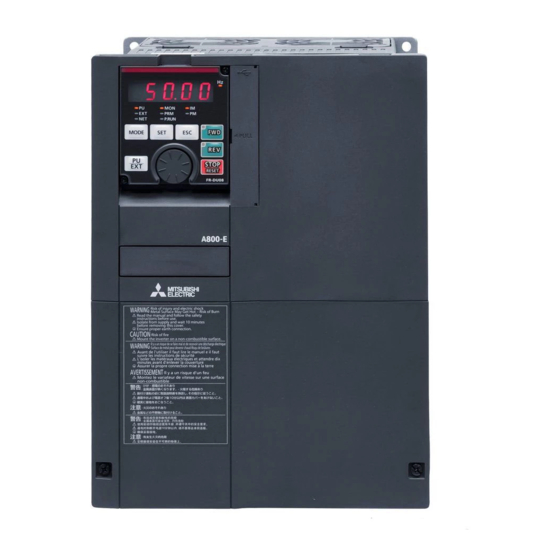
FR-A800-E
INSTALLATION GUIDELINE
FR-A870-02300-E, 02860-E
Thank you for choosing this Mitsubishi Electric Inverter.
This Installation guideline and the enclosed CD-ROM give handling information and precautions for use of this
product.
Do not use this product until you have a full knowledge of the equipment, the safety information and the
instructions.
Please forward this Installation guideline and the CD-ROM to the end user.
A
INSTALLATION AND INSTRUCTIONS ................................................................................1
1
WIRING................................................................................................................................4
2
FAILSAFE OF THE SYSTEM WHICH USES THE INVERTER...............................................18
3
4
PRECAUTIONS FOR USE OF THE INVERTER....................................................................19
5
BASIC OPERATION ...........................................................................................................21
6
TROUBLESHOOTING ........................................................................................................38
7
SPECIFICATIONS ..............................................................................................................41
Art. No.: 405010
14 01 2019
Version check
Version A
CONTENTS
800
Advertisement

Related Manuals for Mitsubishi Electric 800 Series


Summary of Contents for Mitsubishi Electric 800 Series
-
Page 1: Table Of Contents
FR-A800-E INSTALLATION GUIDELINE FR-A870-02300-E, 02860-E Thank you for choosing this Mitsubishi Electric Inverter. This Installation guideline and the enclosed CD-ROM give handling information and precautions for use of this product. Do not use this product until you have a full knowledge of the equipment, the safety information and the instructions. - Page 2 First edition For Maximum Safety Mitsubishi Electric transistorized inverters are not designed or manufactured to be used in equipment or systems in situations that can affect or endanger human life. When considering this product for operation in special applications such as machinery or systems used in passenger transportation, medical, aerospace, atomic power, electric power, or submarine repeating applications, please contact your nearest Mitsubishi Electric sales representative.
- Page 3 A person who took a proper engineering training. Please note if you can take a proper engineering training at your local Mitsubishi Electric office. Such training may be available at your local Mitsubishi Electric office. Contact your local sales office for schedules and locations.
- Page 4 For the installation at an altitude above 1,000 m, derate the rated current 3% per 500 m. If halogen-based materials (fluorine, chlorine, bromine, iodine, etc.) infiltrate into a Mitsubishi Electric product, the product will be damaged. Halogen-based materials are often included in fumigant, which is used to sterilize or disinfect wooden packages. When packaging, prevent residual fumigant components from being infiltrated into Mitsubishi Electric products, or use an alternative sterilization or disinfection method (heat disinfection, etc.) for packaging.
- Page 5 CAUTION The electronic thermal relay function does not guarantee protection of the motor from overheating. It is recommended to install both an external thermal and PTC thermistor for overheat protection. Do not use a magnetic contactor on the inverter input for frequent starting/stopping of the inverter. Otherwise, the life of the inverter decreases.
-
Page 7: Installation And Instructions
1 INSTALLATION AND INSTRUCTIONS 1.1 Inverter Type FR - A8 0 02300 - Circuit board coating Voltage Communication Plated Built-in brake Symbol Symbol Description Symbol Type Symbol (conforming Symbol class type conductor transistor IEC60721-3-3 3C2/3S2) None Without Without None Without Inverter SLD rated 02300, 690 V... - Page 8 INSTALLATION AND INSTRUCTIONS 1.2 Installation of the inverter Install the inverter on a strong surface securely with screws. Leave enough clearances and take cooling measures. Avoid places where the inverter is subjected to direct sunlight, high temperature and high humidity. Install the inverter on a nonflammable surface.
- Page 9 INSTALLATION AND INSTRUCTIONS 1.4 Accessory Earthing (grounding) cable (1): For connection with a communication option CD-ROM (1): Including the Instruction Manual (Hardware) and other documents 1.5 Installing a communication option To use a communication option, the enclosed earthing (grounding) cable needs to be installed. Install the cable according to the following procedure: Insert spacers into the mounting holes that will not be tightened with the option mounting screws.
-
Page 10: Wiring
2 WIRING 2.1 Terminal connection diagrams 2.1.1 CA type Built-in brake transistor model Source logic Main circuit terminal P/+ PR Inrush current limit circuit Control circuit terminal Reactor R/L1 S/L2 Reactor T/L3 Inrush current MCCB limit circuit Reactor R/L1 3-phase S/L2 AC power Reactor... - Page 11 WIRING When using separate power supply for the control circuit, remove the jumper between R1/L11 and S1/L21. The function of these terminals can be changed with the input terminal assignment (Pr. 178 to Pr. 189). (Refer to page 23.) Terminal JOG is also used as the pulse train input terminal. Use Pr. 291 to choose JOG or pulse. Terminal input specifications can be changed by analog input specification switchover (Pr.
- Page 12 WIRING 2.1.2 FM type Built-in brake transistor model Sink logic Main circuit terminal P/+ PR Inrush current Control circuit terminal limit circuit Reactor R/L1 S/L2 Reactor T/L3 Inrush current MCCB limit circuit Reactor R/L1 3-phase S/L2 AC power Reactor T/L3 supply Motor R1/L11...
- Page 13 WIRING When using separate power supply for the control circuit, remove the jumper between R1/L11 and S1/L21. The function of these terminals can be changed with the input terminal assignment (Pr. 178 to Pr. 189). (Refer to page 23.) Terminal JOG is also used as the pulse train input terminal. Use Pr. 291 to choose JOG or pulse. Terminal input specifications can be changed by analog input specification switchover (Pr.
- Page 14 WIRING 2.2 Main circuit terminal 2.2.1 Terminal layout and wiring FR-A870-02300, FR-A870-02860 Charge lamp R1/L11 Power supply terminal block for S1/L21 the control circuit Jumper Terminal screw (hex head hole) T/L3 R/L1 S/L2 Power supply Motor CAUTION The power supply cables must be connected to R/L1, S/L2, T/L3. Never connect the power cable to the U, V, W, of the inverter. Doing so will damage the inverter.
- Page 15 WIRING Wiring method Before the inverter is installed inside the enclosure, terminal block covers must be removed and reinstalled for wiring as required. Loosen the screw on the terminal block cover and remove the cover. Terminal block cover Tilt the upper part of the cover forward, and pull the cover upward. Loosen the terminal screw to lower the inside clamp all the way down.
- Page 16 WIRING Wire connection Select stranded wire with the sheath stripped back or flexible wire with a ferrule. (Do not use solid wire or flexible wire without a ferrule.) Refer to page 11 for details. The ferrule or wire is inserted into a socket of the terminal. Strip the wire as follows.
- Page 17 WIRING 2.3 Wiring fundamentals 2.3.1 Applicable cables and the wiring length Select the recommended cable size to ensure that a voltage drop will be 2% max. If the wiring distance is long between the inverter and motor, a main circuit cable voltage drop will cause the motor torque to decrease especially at the output of a low speed.
- Page 18 WIRING 2.3.2 Total wiring length With general-purpose motor Connect one or more general-purpose motors within the total wiring length 500 m. (The wiring length should be 100 m or less under vector control.) Total wiring length 300 m 300 m 500 m or less 300 m + 300 m = 600 m When driving a 690 V class motor by the inverter, surge voltages attributable to the wiring constants may occur at the motor ter-...
- Page 19 WIRING 2.4 Control circuit terminals 2.4.1 Terminal layout ∗1 1 F/C +24 SD So SOC S1 S2 PC Recommended cable gauge: 0.3 to 0.75 mm² 5 10E 10 SE SE SU IPF OL FU PC RL RM RH RT AU STP MRS RES SD SD STF STR JOG...
- Page 20 WIRING Insert the wires into a socket. When using a single wire or stranded wires without a blade terminal, push the open/close button all the way down with a flathead screwdriver, and insert the wire. Open/close button Flathead screwdriver Wire removal Pull the wire while pushing the open/close button all the way down firmly with a flathead screwdriver.
- Page 21 WIRING 2.4.4 Control logic (sink/source) change Change the control logic of input signals as necessary. To change the control logic, change the jumper connector position on the control circuit board. Connect the jumper connector to the connector pin of the desired control logic. The control logic of input signals is initially set to the sink logic (SINK) for the FM type.
- Page 22 WIRING 2.5 Safety stop function 2.5.1 Function description The terminals related to the safety stop function are shown below. Terminal symbol Terminal function description Between S1 and SIC, S2 and SIC For input of the safety stop channel 1. Open: In safety stop mode For input of the safety stop channel 2.
- Page 23 WIRING 2.5.3 Safety stop function operation Output Output Internal *1, *2 Operation panel indication Input terminal signal Inverter operation terminal Input power safety circuit *8, *9, *10 enable signal status So (SO) SAFE E.SAF Output shutoff — — — Not displayed Not displayed (Safe state) Drive enabled...
-
Page 24: Failsafe Of The System Which Uses The Inverter
Although Mitsubishi Electric assures best quality products, provide an interlock which uses inverter status output signals to pre- vent accidents such as damage to machine when the inverter fails for some reason. -
Page 25: Precautions For Use Of The Inverter
4 PRECAUTIONS FOR USE OF THE INVERTER The FR-A800 series is a highly reliable product, but incorrect peripheral circuit making or operation/handling method may shorten the product life or damage the product. Before starting operation, always recheck the following items: Use crimping terminals with insulation sleeve to wire the power supply and motor. - Page 26 PRECAUTIONS FOR USE OF THE INVERTER When using the electronic bypass operation, electrical and mechanical interlocks are provided between the electronic Interlock bypass contactors MC1 and MC2. R/L1 When using a switching circuit as shown on the right, Power supply S/L2 chattering due to misconfigured sequence or arc generated at T/L3...
-
Page 27: Basic Operation
STOP/RESET key Resets the inverter when the protection function is activated. The setting dial of the Mitsubishi Electric inverters. Turn the setting dial to change the setting of frequency or parameter, etc. Press the setting dial to perform the following operations: ¾... - Page 28 BASIC OPERATION 5.1.2 Basic operation (factory setting) Operation mode switchover/frequency setting External operation mode (At power-ON) PU operation mode PU JOG operation mode Alternate display Example Frequency setting has been written and Value change completed! Second screen Third screen (Output current monitoring) (Output voltage monitoring) First screen (Output frequency monitoring) Display the present...
- Page 29 BASIC OPERATION 5.2 Parameter list For simple variable-speed operation of the inverter, the initial values of the parameters may be used as they are. Set the necessary parameters to meet the load and operational specifications. Parameter setting, change and check can be performed from the operation panel.
- Page 30 BASIC OPERATION Parameter Name Setting range Initial value Parameter Name Setting range Initial value 0, 0.1 to 30 s, 0 to 400 m , Restart coasting time 9999 Motor constant (R2) 9999 9999 9999 Motor constant (L1)/d- Restart cushion time 0 to 60 s 0 to 400 mH, 9999...
- Page 31 BASIC OPERATION Parameter Name Setting range Initial value Parameter Name Setting range Initial value Terminal 4 frequency Voltage reduction setting gain frequency selection during stall 0, 1, 10, 11 0 to 590 Hz 60/50 Hz prevention operation Simple Simple Simple RT signal function PID control automatic 9999...
- Page 32 BASIC OPERATION Parameter Name Setting range Initial value Parameter Name Setting range Initial value AU terminal function Main circuit power OFF 600 s 1 to 3600 s, 9999 selection waiting time JOG terminal function Life alarm display 0 to 9, (0 to 31) selection 12 to 20,...
- Page 33 BASIC OPERATION Parameter Name Setting range Initial value Parameter Name Setting range Initial value Overspeed detection Communication frequency (Excessive EEPROM write 0, 1 9999 0 to 30 Hz, 9999 speed deviation selection detection frequency) Communication error — count Droop gain 0 to 100% Communication reset Droop filter time...
- Page 34 BASIC OPERATION Parameter Name Setting range Initial value Parameter Name Setting range Initial value Model position control Orientation selection 0 to 2, 10 to 12 25 s 0 to 150 s gain Number of machine 0, 1, 3 to 6, 13 to 0 to 32767 Second applied motor 9999...
- Page 35 BASIC OPERATION Parameter Name Setting range Initial value Parameter Name Setting range Initial value Seventh target S-pattern time at a position upper 4 digits completion of 0.1 s 0.1 to 2.5 s deceleration Eighth target position lower 4 digits Output stop frequency 9999 0 to 590 Hz, 9999 Eighth target position...
- Page 36 BASIC OPERATION Parameter Name Setting range Initial value Parameter Name Setting range Initial value Amplitude Second brake 6 Hz 0 to 30 Hz compensation amount operation frequency 0 to 50% during deceleration Second brake 0.3 s 0 to 5 s Amplitude operation time at stop compensation amount...
- Page 37 BASIC OPERATION Parameter Name Setting range Initial value Parameter Name Setting range Initial value Maintenance timer 3 Operation panel 9999 1 to 3, 5 to 14, 17 warning output set 9999 monitor selection 1 0 to 9998, 9999 to 20, 22 to 36, time Operation panel 38, 40 to 45, 50 to...
- Page 38 BASIC OPERATION Parameter Name Setting range Initial value Parameter Name Setting range Initial value Easy gain tuning Excitation ratio 100% 0 to 100% 0 to 2 selection Control terminal Speed control P gain 1 0 to 1000% option-Signal loss 0, 1 detection enable/ Speed control integral 0.333 s...
- Page 39 BASIC OPERATION Parameter Name Setting range Initial value Parameter Name Setting range Initial value Free parameter 1 9999 0 to 9999 Terminal 1 gain 150% 0 to 400% command (torque) (920) Free parameter 2 9999 0 to 9999 Cumulative power Terminal 1 gain 0 to 300% 100%...
- Page 40 BASIC OPERATION Parameter Name Setting range Initial value Parameter Name Setting range Initial value 101 to 131, Analog trigger 1036 0, 1 201 to 229, operation selection 301 to 331, 1037 Analog trigger level 1000 600 to 1400 401 to 430, 501 to 531, Digital source 601 to 630,...
- Page 41 BASIC OPERATION Parameter Name Setting range Initial value Parameter Name Setting range Initial value PID upper limit Third positioning 1134 100% 1232 0 ms 0 to 100% 0 to 20000 ms manipulated value dwell time PID lower limit 0, 1, 2, 10, 11, 12, Third positioning 1135 100%...
- Page 42 BASIC OPERATION Parameter Name Setting range Initial value Parameter Name Setting range Initial value 0, 1, 2, 10, 11, 12, Home position return Tenth positioning 1289 0 to 200% 1261 100, 101, 102, stopper torque subfunction 110, 111, 112 Home position return Eleventh positioning 0.5 s 1290...
- Page 43 BASIC OPERATION Parameter Name Setting range Initial value Parameter Name Setting range Initial value Load status detection Err.CL Fault history clear (0,) 1 signal delay time / Pr.CPY Parameter copy (0,) 1 to 3 1492 load reference 0 to 60 s Initial value change measurement waiting Pr.CHG...
-
Page 44: Troubleshooting
6 TROUBLESHOOTING When a fault occurs in the inverter, the protective function activates, and the PU display automatically changes to one of the fault or alarm indications listed on page 39. If the fault does not correspond to any of the following errors or if you have any other problem, please contact your sales repre- sentative. - Page 45 TROUBLESHOOTING 6.1 Reset method of protective function The inverter can be reset by performing any of the following operations. Note that the internal thermal integrated value of the electronic thermal relay function and the number of retries are cleared (erased) by resetting the inverter. Inverter recovers about 1s after reset is cancelled.
- Page 46 TROUBLESHOOTING Data Data Operation panel indication Name Operation panel indication Name code code Regenerative overvoltage trip Abnormal output current E.OV2 E.CDO (H21) (HC4) during constant speed detection Regenerative overvoltage trip E.OV3 E.IOH Inrush current limit circuit fault (H22) (HC5) during deceleration or stop Inverter overload trip (electronic E.AIE E.THT...
-
Page 47: Specifications
7 SPECIFICATIONS 7.1 Rating 7.1.1 690 V AC power input Model FR-A870- 02300 02860 Applicable motor capacity [kW] ND (initial setting) Rated capacity [kVA] ND (initial setting) Rated current [A] ND (initial setting) 110 % of rated motor capacity for 60 s, 120 % of rated motor capacity for 3 s (max. surrounding air temperature 40 °C) Overload current rating ND (initial setting) 150 % of rated motor capacity for 60 s, 200 % of rated motor capacity for 3 s (max. - Page 48 SPECIFICATIONS 7.1.2 600 V AC power input Model FR-A870- 02300 02860 Applicable motor capacity [kW] ND (initial setting) Rated capacity [kVA] ND (initial setting) Rated current [A] ND (initial setting) 110 % of rated motor capacity for 60 s, 120 % of rated motor capacity for 3 s (max. surrounding air temperature 40 °C) Overload current rating ND (initial setting) 150 % of rated motor capacity for 60 s, 200 % of rated motor capacity for 3 s (max.
- Page 49 SPECIFICATIONS 7.2 Outline dimensions FR-A870-02300, 02860 25.3 4-Ø24 hole (50) (Unit: mm)
-
Page 50: Aappendix
CE marking. The authorized representative in the EU The authorized representative in the EU is shown below. Name: Mitsubishi Electric Europe B.V. Address: Mitsubishi-Electric-Platz 1, 40882 Ratingen, Germany A.1.1 EMC Directive We declare that this inverter conforms with the EMC Directive and affix the CE marking on the inverter. - Page 51 APPENDIX A.1.2 Low Voltage Directive We have self-confirmed our inverters as products compliant to the Low Voltage Directive (Conforming standard EN 61800-5-1) and affix the CE marking on the inverters. Outline of instructions Do not use an earth leakage current breaker as an electric shock protector without connecting the equipment to the earth. Connect the equipment to the earth securely.
- Page 52 APPENDIX A.2 Instructions for UL and cUL The FR-A800 series (690 V class) are UL certified with the maximum voltage of 600 V. (Conforming standard UL 61800-5-1, CSA C22.2 No.274-13) A.2.1 General precautions WARNING The bus capacitor discharge time is 10 minutes. Before starting wiring or inspection, switch power off, wait for more than 10 min- utes, and check for residual voltage between terminal P/+ and N/- with a meter etc., to avoid a hazard of electrical shock.
- Page 53 APPENDIX A.2.6 Motor overload protection When using the electronic thermal relay function as motor overload protection, set the rated motor current to Pr. 9 "Electronic thermal O/L relay". Electronic thermal relay function operation characteristic This function detects the overload (overheat) of the motor, Pr.
- Page 54 APPENDIX A.3 SERIAL number check The SERIAL number can be checked on the inverter rating plate or package. (Refer to page 1.) Rating plate example „ Symbol Year Month Control number SERIAL The SERIAL consists of one symbol, two characters indicating production year and month, and six characters indicating control number.
- Page 56 Fax: +356 (0)21 / 697 817 Phone: +1 (847) 478-2100 Fax: +1 (847) 478-0328 Mitsubishi Electric Europe B.V. / FA - European Business Group / Mitsubishi-Electric-Platz 1 / D-40882 Ratingen / Germany / Tel.: +49(0)2102-4860 / Fax: +49(0)2102-4861120 / info@mitsubishi-automation.com / https://eu3a.mitsubishielectric.com...