ABB SACE Emax 2 Installation, Operation And Maintenance Instructions
Hide thumbs
Also See for SACE Emax 2:

Related Manuals for ABB SACE Emax 2


Summary of Contents for ABB SACE Emax 2
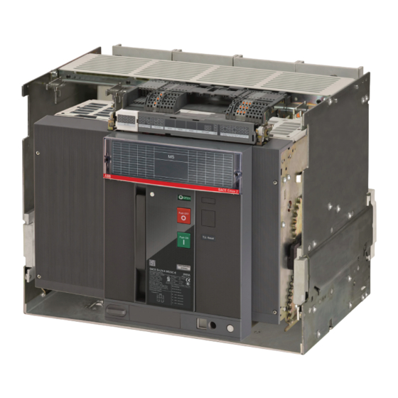
- Page 1 DOC. N° 1SDH002083A1002 - ECN000119014 - Rev. A SACE Emax 2 Emax2 E4.2 MS/DC-E low voltage air switch-disconnectors Installation, operation and maintenance instructions for the installer and the user...
- Page 2 ABB | SACE Emax 2 2 | © 2021 ABB | 1SDH002083A1002 - ECN000119014 - Rev. A...
-
Page 3: Table Of Contents
Putting into service and maintenance ........38 1 - Putting into service ............38 References ..................4 Introduction ................ 38 1 - ABB documentation mentioned in this manual ....4 General checks ..............38 Check accessories .............. 39 Emax E4.2 circuit-breakers ............5 Final check list .............. - Page 4 1SDH002083A1002 - ECN000119014 - Rev. A II | © 2021 ABB SACE Emax 2...
-
Page 5: Glossary
ABB | SACE Emax 2 Glossary Term Description SACE Emax 2 DC New series of ABB SACE air switch disconnectors Disconnector configurations: four-pole (4P) 3 | © 2021 ABB | 1SDH002083A1002 - ECN000119014 - Rev. A Glossary |... -
Page 6: References
Technical catalog 1SDC200023D0906 Anti-insertion lock 1SDH001000R0701 Wiring diagrams 1SDM000017A1001 ABB Library Download Center ownloAD enteR Emax 2 Products RoDuCtS 4 | © 2021 ABB | 1SDH002083A1002 - ECN000119014 - Rev. A References | 1 - ABB documentation mentioned in this manual... -
Page 7: Emax E4.2 Circuit-Breakers
All the remaining operations described in the handbook must be performed by skilled persons, in the electrical field. ABB declines all liability for damage to persons or property caused by failure to comply with the instructions in this document. -
Page 8: Safety
• these warnings and alarms do not include all conceivable ways to make installation, use and maintenance recommended by ABB or not, that may be made, or possible consequences and complications of each conceivable way, nor shall ABB investigate all those ways. -
Page 9: Regulations
ABB | SACE Emax 2 3 - Regulations Standards Sace Emax 2 MS/DC-E series circuit-breakers conform to international standards: • IEC 60947-3 • EN 60947-3 • UL 489F • UL 489B • GB/T 14048.3 They comply with the following EC directives: •... -
Page 10: Management Operations
ABB | SACE Emax 2 Management operations 1 - Transport and checking on receipt Introduction In view of their weight, Sace Emax 2/MS 1500 V DC series switch disconnectors require particular care during transport and handling. They are distributed with following packages: •... -
Page 11: Identification Of Packaging
Damage and Discrepancy If there is any damage to the packaging upon receipt and / or inconsistencies between order and product identification label or product please contact ABB. Damage to the packaging must be reported no later than Report seven days from receipt of the material. -
Page 12: Storage Method
WARNING! If the package with the terminals is joined to that of the circuit-breaker (UL 2500A-3200A) additional packages cannot be stacked on top. Figure 6 10 | © 2021 ABB | 1SDH002083A1002 - ECN000119014 - Rev. A Management operations | 1 - Transport and checking on receipt... -
Page 13: Unpacking And Handling
Remove the packing box by lifting it upwards. See Figure 10. Figure 10 Figure 9 Continued on the next page 11 | © 2021 ABB | 1SDH002083A1002 - ECN000119014 - Rev. A Management operations | 2 - Unpacking and handling... -
Page 14: Disposal Of Packing Materials
Standards Current Configuration 4000A 3200A 2500A 2000A 1600A IEC 60947-3 4000A 3200A 2500A 2000A 1600A Continued on the next page 12 | © 2021 ABB | 1SDH002083A1002 - ECN000119014 - Rev. A Management operations | 2 - Unpacking and handling... -
Page 15: Lift The Fixed Circuit Breaker Or The Moving Part Of A Withdrawable Circuit-Breaker
Lift the fixed part from the base of the package using the purpose-made lifting points of the fixed part. See Figure 16. IMPORTANT: keep the lifting plates and manual until the disconnector is dismantled. 13 | © 2021 ABB | 1SDH002083A1002 - ECN000119014 - Rev. A Management operations | 2 - Unpacking and handling... -
Page 16: Description
The moving and fixed parts are coupled together by special clamps installed on the movable part. Figure 18 Figure 17 Figure 19 14 | © 2021 ABB | 1SDH002083A1002 - ECN000119014 - Rev. A Management operations | 3 - Description... -
Page 17: Front Description
CB open (O) / closed (I) indicator Opening pushbutton Mechanical signalling of tripped TU Closing pushbutton Springs charged-discharged signalling device Electrical data plate 15 | © 2021 ABB | 1SDH002083A1002 - ECN000119014 - Rev. A Management operations | 3 - Description... -
Page 18: Description Of Iec+Ccc Specification Data Plate
UL file number Standards Rated service voltage Utilization category Admissible rated short-time current Impulse voltage Insulation voltage Rated voltage of accessories Circuit diagram 16 | © 2021 ABB | 1SDH002083A1002 - ECN000119014 - Rev. A Management operations | 3 - Description... -
Page 19: Description Of Ul+Iec+Ccc Specification Data Plate
UL file number Standards Rated service voltage Utilization category Admissible rated short-time current Impulse voltage Insulation voltage Rated voltage of accessories Circuit diagram 17 | © 2021 ABB | 1SDH002083A1002 - ECN000119014 - Rev. A Management operations | 3 - Description... -
Page 20: Manual Operations For Opening And Closing The Circuit-Breaker
Opening - Press the opening pushbutton “O - Push OFF” as indicated in Figure 29. Push OFF Figure 28 Figure 29 Continued on the next page 18 | © 2021 ABB | 1SDH002083A1002 - ECN000119014 - Rev. A Management operations | 3 - Description... -
Page 21: Mechanical Status Indicators
• The pushbutton for enabling the insertion/extraction crank of a withdrawable circuit-breaker is pres- sed. Figure 31 Figure 32 Figure 33 Figure 34 Figure 35 19 | © 2021 ABB | 1SDH002083A1002 - ECN000119014 - Rev. A Management operations | 3 - Description... -
Page 22: Circuit Breaker Racking-In/Racking-Out Operations
See Figure 39. Figure 39 Figure 38 Continued on the next page 20 | © 2021 ABB | 1SDH002083A1002 - ECN000119014 - Rev. A Management operations | 3 - Description... - Page 23 Grip the guide levers of the fixed part and push them until the moving part stops. See Figure 42. PUSH Figure 42 Continued on the next page 21 | © 2021 ABB | 1SDH002083A1002 - ECN000119014 - Rev. A Management operations | 3 - Description...
- Page 24 11. Press the lock button and rotate the crank clockwise until it comes out and the indicator shows that the circuit-breaker is in CONNECT position. See Figure 46. Figure 46 Continued on the next page 22 | © 2021 ABB | 1SDH002083A1002 - ECN000119014 - Rev. A Management operations | 3 - Description...
- Page 25 To extract the moving part from the fixed part, perform the same steps indicated for insertion in reverse order. Figure 49 Continued on the next page 23 | © 2021 ABB | 1SDH002083A1002 - ECN000119014 - Rev. A Management operations | 3 - Description...
-
Page 26: Mechanical Position Indicators
• circuit-breaker in test position (see Figure 52) • circuit-breaker in CONNECT position (see Figure 53) Figure 51 Figure 52 Figure 53 24 | © 2021 ABB | 1SDH002083A1002 - ECN000119014 - Rev. A Management operations | 3 - Description... -
Page 27: Environmental Conditions
Fix the circuit-breaker to a horizontal surface using 4 x M10 screws. See Figure 54. breaker Figure 54 WARNING! Emax2 E4.2 MS/DC-E circuit-breakers can only be installed in the vertical position. 25 | © 2021 ABB | 1SDH002083A1002 - ECN000119014 - Rev. A Management operations | 5 - Installation... -
Page 28: Mounting Anti-Insertion Locks
Mounting the fixed part of the Fasten the fixed part to a horizontal surface using four M8 × 25 screws. The screws are supplied by ABB. See Figure 56. Tighten the screws with tightening torque = 21 N m - 186 lb in. -
Page 29: Types Of Terminal
The following are the different types of terminal: 1600A IEC 1600A UL 3200A IEC 2500A UL 2000A IEC 2000A UL 4000A IEC 3200A UL 2500A IEC Figure 57 27 | © 2021 ABB | 1SDH002083A1002 - ECN000119014 - Rev. A Management operations | 5 - Installation... -
Page 30: Change Of Position Of The Vertical/Horizontal Terminals
The sizing of the busbars is specified by the designer of the electrical switchgear. Figure 62 Continued on the next page 28 | © 2021 ABB | 1SDH002083A1002 - ECN000119014 - Rev. A Management operations | 5 - Installation... - Page 31 70 N m - 619.5 lb in tightening torque. NOTE: the information on the performances of the circuit-breakers in switchboards is available on the website: http://new.abb.com/low-voltage/products/circuit-breakers/emax2. 29 | © 2021 ABB | 1SDH002083A1002 - ECN000119014 - Rev. A Management operations | 5 - Installation...
-
Page 32: Overall Dimensions
- E4.2-E W IV 4PS H-V 2000A UL - E4.2-E W IV 2PS V 3200A UL 1SDH001001R0313 1SDH001001R0314 - E4.2-E W IV 4PS V 3200A UL 30 | © 2021 ABB | 1SDH002083A1002 - ECN000119014 - Rev. A Management operations | 5 - Installation... -
Page 33: Positioning Anchor Plates
Positioning anchor plates E4.2-A 3200 A The anchor plates must be positioned as indicated in the figure. 30mm max. Bus Bracing Figure 64 31 | © 2021 ABB | 1SDH002083A1002 - ECN000119014 - Rev. A Management operations | 5 - Installation... -
Page 34: Grounding
After assembly of the conductor, tighten the screw with a torque of 2 N m - 17.7 lb in. Figure 65 Figure 66 32 | © 2021 ABB | 1SDH002083A1002 - ECN000119014 - Rev. A Management operations | 5 - Installation... -
Page 35: Accessories
Overview and connection Emax 2 circuit-breakers have a set of electronic, electrical and mechanical accessories, the availability of which depends on the CB model. Consult manual 1SDH001330R1002 for details, circuit diagrams 1SDM000017A1001 and assembly instructions for the connection. 33 | © 2021 ABB | 1SDH002083A1002 - ECN000119014 - Rev. A Accessories | 1 - Overview... -
Page 36: Wiring Diagrams
Switch-disconnector for networks with negative polarity connected to earth. LOAD LOAD Diagram C - Cable entrance from below Diagram D - Cable entrance from above Continued on the next page 34 | © 2021 ABB | 1SDH002083A1002 - ECN000119014 - Rev. A Accessories | 2 - Wiring diagrams... - Page 37 S33M/2 SPRINGS LOADED POSITION SIGNALING CONTACT Q/10 OPEN/CLOSE AUXILIARY CONTACTS OF CIRCUIT-BREAKER SWITCH - DISCONNECTOR (SECOND SET) Continued on the next page 35 | © 2021 ABB | 1SDH002083A1002 - ECN000119014 - Rev. A Accessories | 2 - Wiring diagrams...
- Page 38 24 V. Then Q5, Q6, Q7 are 400 V, while Q8, Q9, Q10 are 24 V. Always supplied with motor for loading the closing springs in Fig.13. Continued on the next page 36 | © 2021 ABB | 1SDH002083A1002 - ECN000119014 - Rev. A Accessories | 2 - Wiring diagrams...
-
Page 39: Mechanical Accessories
Incompatible with YU; standard for UL version. A maximum of two accessories are available for YO and YU. Not available for withdrawable circuit-breakers with lateral fastening. 37 | © 2021 ABB | 1SDH002083A1002 - ECN000119014 - Rev. A Accessories | 2 - Wiring diagrams... -
Page 40: Putting Into Service And Maintenance
WARNING! in the presence of an undervoltage coil the circuit-breaker can be closed only after the trip unit is energized NOTE: for safety reasons, ABB strongly advises you to change the password right from the first access and to keep it with care. -
Page 41: Check Accessories
Result: The circuit-breaker closes correctly; the signals are normal. if present. (**) withdrawable versions only. Continued on the next page 39 | © 2021 ABB | 1SDH002083A1002 - ECN000119014 - Rev. A Putting into service and maintenance | 1 - Putting into service... - Page 42 85% and 110% of the rated voltage for the auxiliary accessories. auxiliary voltage if present. (**) withdrawable versions only. 40 | © 2021 ABB | 1SDH002083A1002 - ECN000119014 - Rev. A Putting into service and maintenance | 1 - Putting into service...
-
Page 43: Final Check List
- springs discharged O - OPEN and white spring signalling device DISCHARGED SPRING 41 | © 2021 ABB | 1SDH002083A1002 - ECN000119014 - Rev. A Putting into service and maintenance | 1 - Putting into service... -
Page 44: Identification Of Alarms Or Failures
The operating mechanism is blocked Contact ABB opening pushbutton is pressed Continued on the next page 42 | © 2021 ABB | 1SDH002083A1002 - ECN000119014 - Rev. A Putting into service and maintenance | 2 - Identification of alarms or failures... - Page 45 The lock in open position is defective Contact ABB Continued on the next page 43 | © 2021 ABB | 1SDH002083A1002 - ECN000119014 - Rev. A Putting into service and maintenance | 2 - Identification of alarms or failures...
-
Page 46: Maintenance
ABB declines all liability for damage to persons or property caused by failure to comply with the instructions in this document. Circuit-breaker life The circuit-breakers SACE Emax 2, with or without opening or closing coils, can withstand the following operating cycles if regularly serviced. For further information see chapter 4 - Environmental conditions on page 25. -
Page 47: Maintenance Schedule
ABB | SACE Emax 2 Maintenance schedule Proper maintenance of the equipment allows good electromechanical operation to be maintained over time. The maintenance plan for SACE Emax 2 circuit-breakers specifies two periodic levels of maintenance for the different types of site conditions. -
Page 48: First Level Maintenance
46 | © 2021 ABB | 1SDH002083A1002 - ECN000119014 - Rev. A Putting into service and maintenance | 4 - First level maintenance... -
Page 49: Disassembly Operations
If there is an undervoltage coil (G), remove it, and discharge the springs of the operating mechanism for closing and opening the circuit breaker. Figure 69 - Removing the undervoltage coil 47 | © 2021 ABB | 1SDH002083A1002 - ECN000119014 - Rev. A Putting into service and maintenance | 4 - First level maintenance... -
Page 50: Cleaning And Lubrication Of The Operating Mechanism
NOTE: it is advisable to replace the gear motor if it has performed more than 10000 spring charging operations or reached 50% of the declared mechanical life of the circuit-breaker. 48 | © 2021 ABB | 1SDH002083A1002 - ECN000119014 - Rev. A Putting into service and maintenance | 4 - First level maintenance... -
Page 51: Final Checks
After a trip due to a short-circuit. Figure 71 Use Mobilgrease 28, also available in the ABB greasing kit. 49 | © 2021 ABB | 1SDH002083A1002 - ECN000119014 - Rev. A Putting into service and maintenance | 4 - First level maintenance... -
Page 52: Second Level Maintenance
Make sure that the screws that fasten the fixed part to the switchgear are well tightened (M8 - 25 N m - 221.27 lb in) 50 | © 2021 ABB | 1SDH002083A1002 - ECN000119014 - Rev. A Putting into service and maintenance | 5 - Second level maintenance... -
Page 53: Circuit-Breaker Connections And Connections Between Circuit- Breaker And Switchboard
51 | © 2021 ABB | 1SDH002083A1002 - ECN000119014 - Rev. A Putting into service and maintenance | 5 - Second level maintenance... -
Page 54: Disassembly Operations
Figure 76 - Removing the undervoltage coil Continued on the next page 52 | © 2021 ABB | 1SDH002083A1002 - ECN000119014 - Rev. A Putting into service and maintenance | 5 - Second level maintenance... - Page 55 Before cleaning and lubrication of the operating mechanism, you must remove the protection trip unit. For information about removal, see the document 1SDH001000R0523, or request the intervention of a technician ABB. 53 | © 2021 ABB | 1SDH002083A1002 - ECN000119014 - Rev. A Putting into service and maintenance | 5 - Second level maintenance...
-
Page 56: Cleaning And Lubrication Of The Operating Mechanism
Figure 80 - Lubrication of the closing hook Figure 81 - Lubrication of opening latch and shaft Continued on the next page 54 | © 2021 ABB | 1SDH002083A1002 - ECN000119014 - Rev. A Putting into service and maintenance | 5 - Second level maintenance... -
Page 57: Inspection Of Electrical And Mechanical Accessories
NOTE: it is advisable to replace the gear motor if it has performed more than 10000 spring charging operations or reached 50% of the declared mechanical life of the circuit-breaker. 55 | © 2021 ABB | 1SDH002083A1002 - ECN000119014 - Rev. A Putting into service and maintenance | 5 - Second level maintenance... -
Page 58: Check For Wear On The Contacts
-> OK Figure 84 - Checking the breaking gaps Close the circuit-breaker and check dimension A. Contact ABB Sace (*) if dimension A is incorrect. If dimension A is correct, open the circuit-breaker again and re-assemble the arc chutes. -
Page 59: Final Checks
• auxiliary contacts of the circuit-breaker, if provided. • lock for circuit-breaker in open position (key or padlock), if provided 57 | © 2021 ABB | 1SDH002083A1002 - ECN000119014 - Rev. A Putting into service and maintenance | 5 - Second level maintenance... -
Page 60: Interlock Check
After a trip due to a short-circuit. Figure 85 Use Mobilgrease 28, also available in the ABB greasing kit. 58 | © 2021 ABB | 1SDH002083A1002 - ECN000119014 - Rev. A Putting into service and maintenance | 5 - Second level maintenance... -
Page 61: Decommissioning And Treatment At End Of Life
ABB | SACE Emax 2 6 - Decommissioning and treatment at end of life Safety standards During the early stages of the process of decommissioning and end of life treatment of SACE Emax 2 circuit- breakers, observe the following safety rules: •... - Page 62 ABB | SACE Emax 2 60 | © 2021 ABB | 1SDH002083A1002 - ECN000119014 - Rev. A Putting into service and maintenance | 6 - Decommissioning and treatment at end of life...