
Related Manuals for Toro 38066


Summary of Contents for Toro 38066
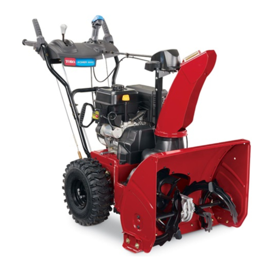
- Page 1 Form No. 3326-400 Rev A 824 XL Power Throw Snowthrower Model No. 38066—220000001 and Up Operator’s Manual International English (GB)
-
Page 2: Table Of Contents
....... . Dealer or Toro Customer Service and have the model and Installing the Discharge Chute . -
Page 3: Safety
The following instructions have been adapted from the objects being thrown into the eyes. Always wear safety ANSI/OPEI B71.3–1995 standard and the ISO 8437:1989 glasses or eye shields while operating, adjusting, or standard. Information or terminology specific to Toro repairing the snowthrower. snowthrowers is enclosed in parenthesis. -
Page 4: Toro Snowthrower Safety
Do not run the engine indoors, except when starting it The following list contains safety information specific to and for moving the snowthrower in or out of the Toro products or other safety information that you must building. Open the outside doors; exhaust fumes are know. -
Page 5: Sound Pressure Level
Do not use the snowthrower on a roof. To ensure the best performance and safety, purchase only genuine Toro replacement parts and accessories. Do not touch the engine while it is running or soon after it has stopped because the engine may be hot enough to Sound Pressure Level cause a burn. -
Page 7: Safety And Instruction Decals
Safety and Instruction Decals Safety decals and instructions are easily visible to the operator and are located near any area of potential danger. Replace any decal that is damaged or lost. 63-9920 94-2558 1. Cutting/dismemberment in impeller hazard—stay away from moving parts, and stop the engine and remove the key before performing maintenance 93-8034... -
Page 8: Assembly
Tecumseh Part No. 36501 1. Primer Tecumseh Part No. 35077 1. Key ignition 4. Fast 2. Engage to start the 5. Increasing scale engine 6. Slow Tecumseh Part No. 37119 3. Disengage to stop the 7. Stop the engine engine 1. -
Page 9: Installing The Handle Assembly
DESCRIPTION QTY. Worm gear Bracket Carriage bolt Installing the chute control gear Flat washer Locknut Skids Flange-head bolts—3/4 in. (1.9 cm) Installing the skids Flat washers and locknuts Ignition key Starting and stopping the engine Installing the Handle Assembly 1. Remove the tie straps that secure the control rods to the handle assembly. -
Page 10: Installing The Speed Selector Rod
Installing the Speed Selector 1. Pull the speed selector arm (Fig. 7) to the most outward position. m-2665 m-2672 Figure 5 Figure 7 1. Engine 3. Traction rod 1. Speed selector arm 3. Flat washer 2. Chute control rod 4. Side plate 2. -
Page 11: Installing The Traction Rod
Note: If the speed selector does not move into fifth gear or 4. Move the speed selector (Fig. 20) into fifth gear. does not meet your speed requirements, adjust the speed 5. Slowly pull the snowthrower backward while slowly selector. Refer to Adjusting the Speed Selector on page 22. pressing the traction control lever toward the handgrip. -
Page 12: Installing The Discharge Chute
Installing the Discharge Chute 1. Apply a light coat of low-temperature grease to the chute ring (Fig. 14). m-2628 Figure 13 1. Handgrip 3. Approximately four inches (10.2 centimeters) 2. Two inches (five m-168 centimeters) 4. Auger/impeller drive control lever Figure 14 1. -
Page 13: Installing The Skids
Installing the Chute Control 8. Slide the worm gear into the teeth of the chute gear and tighten the locknut. Gear 9. Operate the chute control. If the chute control binds, apply a light coat of grease to the worm gear and move 1. -
Page 14: Before Starting
7. Insert a washer and a locknut behind (on the inside of) the side plate (Fig. 18). Do not tighten the bolts. Note: The following steps describe how to adjust the skids for paved surfaces. For gravel or crushed rock surfaces, refer to Adjusting the Skids and the Scraper on page 21. -
Page 15: Checking The Tire Pressure
Important Do not add oil to the gasoline. Danger Important Do not use methanol, gasoline containing methanol, gasohol containing more than 10% ethanol, When fueling, under certain circumstances, a premium gasoline, or white gas. Using these fuels can static charge can develop, igniting the gasoline. A damage the engine’s fuel system. -
Page 16: Reviewing The Maintenance Schedule
Reviewing the Maintenance Ignition Switch (Fig. 21)—Insert the key before starting the engine. To stop the engine, remove the key. Schedule Review the Recommended Maintenance Schedule on page 20. You may need to perform one or more additional procedures before or soon after you begin operating the snowthrower. -
Page 17: Removing The Carburetor Heater Box
Figure 23 1. Recoil starter Figure 25 1. Green ground wire clip Removing the Carburetor Heater Box 7. Install the choke knob. If you operate the engine when the air temperature is above 8. Insert the ignition key. 40 F (4 C), remove the carburetor heater box (Fig. 24). 9. -
Page 18: Stopping The Engine
8. Grasp the recoil starter handle (Fig. 23) and pull it out 2. Run the engine for a few minutes to dry off any slowly until positive engagement results; then pull the accumulated moisture. handle vigorously to start the engine. 3. -
Page 19: Snowthrowing Tips
2. Slide the bracket and the headlight to the desired Discharge the snow downwind whenever possible. position and tighten the nuts on the U-bolt. Do not overload the snowthrower by clearing snow at 3. Tighten the pivot bolt on the rear of the headlight too fast a rate. -
Page 20: Maintenance
Maintenance Note: Determine the left and right sides of the machine from the normal operating position. Recommended Maintenance Schedule Maintenance Service Maintenance Procedure Interval Check the engine oil level. Refer to Checking the Engine Oil Level on page 21. Check the auger gearbox oil level and add oil if necessary. Refer to Checking the Auger Gearbox Oil Level on page 21. -
Page 21: Checking The Engine Oil Level
Caution If you leave the wire on the spark plug, someone could accidently start the engine and seriously injure you or other bystanders. Disconnect the wire from the spark plug before you do any maintenance. Set the wire aside so that it does not accidentally contact the spark plug. -
Page 22: Adjusting The Speed Selector
5. Loosen the four flange bolts that secure both skids to 2. Disconnect the wire from the spark plug and ensure that the auger side plates (Fig. 18) until the skids slide up the wire does not contact the plug (Fig. 24). and down easily. - Page 23 m-4040 Figure 30 1. Upper belt cover 2. Bolt (3) 4. Loosen the auger brake arm assembly by loosening the rearmost screw and removing the front screw (Fig. 31). m-3331 Figure 32 1. Traction idler pulley 7. Belt guide 2. Idler pulley 8.
-
Page 24: Adjusting The Auger/Impeller Drive Belt
m-2677 m-2678 Figure 33 Figure 35 1. Traction drive belt 4. Engine pulley sheave 2. Engine pulley 5. Auger/impeller drive belt 1. Tabs in holes 3. Indexing rib in indexing notch 19. Have someone squeeze the auger/impeller drive control lever (Fig. 20) against the handgrip, and install the belt 14. -
Page 25: Replacing The Auger/Impeller Drive Belt
5. Remove the idler pulley spring (Fig. 31). Let the brake arm assembly to hang free but out of the way. Danger 6. Remove the two bolts, two washers, and two lock Improperly adjusting the auger/impeller may washers that secure the belt guide (Fig. 32). cause it to turn when disengaged. -
Page 26: Lubricating The Snowthrower
Auger/Impeller Drive Belt on page 24. If the problem persists, take the snowthrower to an Authorized Service Dealer for service. Lubricating the Snowthrower Lightly lubricate all moving parts of the snowthrower after every 15 operating hours and at the end of the snowthrowing season. -
Page 27: Replacing The Spark Plug
2. Disconnect the wire from the spark plug and ensure that the wire does not contact the plug (Fig. 24). 3. Clean the area around the oil drain plug (Fig. 39). Figure 40 1. 0.030 in. (0.76 mm) 7. Install the spark plug by hand and then torque it to 15 ft-lb (20.4 N m). -
Page 28: Storage
9. Start the snowthrower and run the engine until it stops. Preparing the Snowthrower Repeat this step two more times to ensure that the fuel tank and the carburetor are empty. 1. Lubricate the snowthrower. Refer to Lubricating the Snowthrower on page 26. Storage 2. -
Page 29: Troubleshooting
Troubleshooting Toro designed and built your snowthrower for trouble-free operation. Check the following components and items carefully, and refer to Maintenance on page 20 for more information. If a problem continues, see an Authorized Service Dealer. Problem Possible Causes Corrective Action Electric starter does not turn 1. - Page 30 Problem Possible Causes Corrective Action 3. The fuel tank is nearly empty or 3. Drain and fill the fuel tank with contains stale fuel. fresh gasoline (not more than 30 days old). If the problem persists, contact an Authorized Service Dealer. 4.