Table of Contents
Advertisement
OptiX OSN 8800/6800/3800
Hardware Description
4 OptiX OSN 8800 Subrack ............................................................................................................ 1
4.1 Update Description ....................................................................................................................................................... 1
4.2 OptiX OSN 8800 T64 Subrack ..................................................................................................................................... 4
4.2.1 Structure ..................................................................................................................................................................... 4
4.2.2 Slot Description ......................................................................................................................................................... 6
4.2.3 Management Interfaces .............................................................................................................................................. 8
4.2.4 Cross-Connect Capacities ........................................................................................................................................ 20
4.2.5 Fan and Heat Dissipation ......................................................................................................................................... 22
4.2.6 Power Consumption ................................................................................................................................................. 29
4.2.7 Mechanical Specifications ....................................................................................................................................... 31
4.3 OptiX OSN 8800 T32 Subrack ................................................................................................................................... 31
4.3.1 Structure ................................................................................................................................................................... 31
4.3.2 Slot Description ....................................................................................................................................................... 33
4.3.3 Management Interfaces ............................................................................................................................................ 35
4.3.4 Cross-Connect Capacities ........................................................................................................................................ 35
4.3.5 Fan and Heat Dissipation ......................................................................................................................................... 36
4.3.6 Power Consumption ................................................................................................................................................. 42
4.3.7 Mechanical Specifications ....................................................................................................................................... 44
4.4 OptiX OSN 8800 T16 Subrack ................................................................................................................................... 45
4.4.1 Structure ................................................................................................................................................................... 45
4.4.2 Slot Description ....................................................................................................................................................... 46
4.4.3 Management Interfaces ............................................................................................................................................ 47
4.4.4 Cross-Connect Capacities ........................................................................................................................................ 58
4.4.5 Fan and Heat Dissipation ......................................................................................................................................... 59
4.4.6 Power Consumption ................................................................................................................................................. 64
4.4.7 Mechanical Specifications ....................................................................................................................................... 66
4.5 OptiX OSN 8800 Universal Platform Subrack ........................................................................................................... 66
4.5.1 Structure ................................................................................................................................................................... 67
4.5.2 Slot Description ....................................................................................................................................................... 68
4.5.3 Management Interfaces ............................................................................................................................................ 71
4.5.4 Fan and Heat Dissipation ......................................................................................................................................... 81
4.5.5 DC Power Consumption .......................................................................................................................................... 87
Issue 01 (2016-03-10)
Huawei Proprietary and Confidential
Copyright © Huawei Technologies Co., Ltd.
Contents
Contents
i
Advertisement
Table of Contents

Related Manuals for Huawei OptiX OSN 8800


Summary of Contents for Huawei OptiX OSN 8800
-
Page 1: Table Of Contents
4.4.5 Fan and Heat Dissipation ............................59 4.4.6 Power Consumption ..............................64 4.4.7 Mechanical Specifications ............................66 4.5 OptiX OSN 8800 Universal Platform Subrack ......................66 4.5.1 Structure ................................... 67 4.5.2 Slot Description ............................... 68 4.5.3 Management Interfaces ............................71 4.5.4 Fan and Heat Dissipation ............................ - Page 2 OptiX OSN 8800/6800/3800 Hardware Description Contents 4.5.6 AC Power Consumption ............................88 4.5.7 Mechanical Specifications ............................90 Issue 01 (2016-03-10) Huawei Proprietary and Confidential Copyright © Huawei Technologies Co., Ltd.
-
Page 3: Optix Osn 8800 Subrack
There are two types of OptiX OSN 8800 T32 subracks: enhanced and general. 4.4 OptiX OSN 8800 T16 Subrack 4.5 OptiX OSN 8800 Universal Platform Subrack The OptiX OSN 8800 universal platform subrack can be installed in an N63B, N66B, or 19-inch cabinet. The subrack has 16 service slots. 4.1 Update Description This section describes the hardware updates in V100R006C01 and later versions as well as the reasons for the updates. - Page 4 Hardware Update Reason for the Update Added the OptiX OSN 8800 The OptiX OSN 8800 universal platform subrack can be universal platform subrack. installed in an N63B, N66B, or 19-inch cabinet. The subrack has 16 service slots and its rated current is 60 A.
- Page 5 N4SLQ16, and N4SLQ64 boards in the OptiX OSN 8800 T16 subrack. Added the OptiX OSN 8800 The OptiX OSN 8800 T64 subrack has been enhanced to T64 enhanced subrack. support the use of large-capacity service boards. Added the OptiX OSN 8800 The OptiX OSN 8800 platform subrack can be installed platform subrack.
-
Page 6: Optix Osn 8800 T64 Subrack
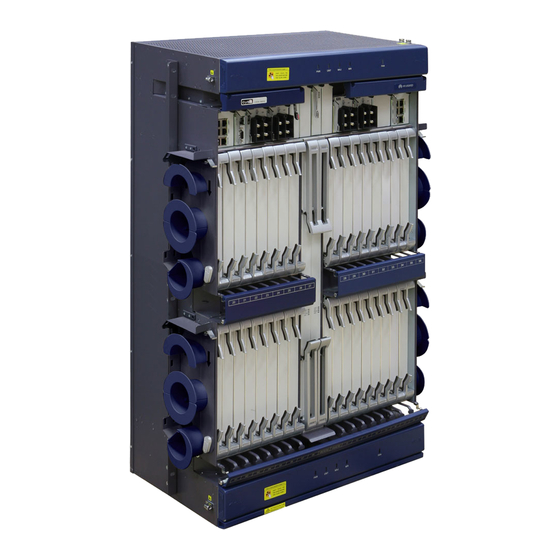
4.2 OptiX OSN 8800 T64 Subrack There are two types of OptiX OSN 8800 T64 subracks: enhanced and general. In this document, "OptiX OSN 8800 T64" refers to both enhanced OptiX OSN 8800 T64 and general OptiX OSN 8800 T64 subracks unless otherwise specified. - Page 7 OptiX OSN 8800/6800/3800 Hardware Description 4 OptiX OSN 8800 Subrack Figure 4-1 Structure of OptiX OSN 8800 T64 subrack OSN 8800 T64 OSN 8800 T64 1. Board area 2. Fiber cabling area 3. Fan tray assembly Issue 01 (2016-03-10) Huawei Proprietary and Confidential...
-
Page 8: Slot Description
A subrack identified by "Enhanced" is an enhanced OptiX OSN 8800 T64 subrack, and the one that is not identified by "Enhanced" is a universal OptiX OSN 8800 T64 subrack. These two types of subracks are displayed as OSN8800 T64 Enhanced and OSN8800 T64 Standard respectively on the U2000. - Page 9 Pair slots refer to a pair of slots whose resident boards' overhead can be processed by the buses on the backplanes. In a general OptiX OSN 8800 T64 subrack, IU73 and IU84 are reserved for future use, and IU72 and IU83 are used to house AUX boards. In an enhanced OptiX OSN 8800 T64 subrack, IU72 and IU83 are used to house the active AUX boards, and IU73 and IU84 are used to house the standby AUX boards.
-
Page 10: Management Interfaces
IU9 & IU43 TN52AUX Enhanced OptiX 8800 T64: IU72 & IU73, IU83 & IU84 4.2.3 Management Interfaces The OptiX OSN 8800 T64 subrack provides various communication and maintenance interfaces for the management and maintenance purposes, as shown in Table 4-1. - Page 11 OptiX OSN 8800/6800/3800 Hardware Description 4 OptiX OSN 8800 Subrack Boar Front Panel Interface Specification Name Conne Pino Description ctor Type NOTE When inter-subrack protection is configured, the ETH3 interface cannot be used for the communication between the master and slave subracks.
- Page 12 OptiX OSN 8800/6800/3800 Hardware Description 4 OptiX OSN 8800 Subrack Boar Front Panel Interface Specification Name Conne Pino Description ctor Type (W): 5 W Maximum power consumption : 7 W ALMO Table Alarm outputs are sent to Dimensions RJ45 ...
- Page 13 OptiX OSN 8800/6800/3800 Hardware Description 4 OptiX OSN 8800 Subrack Boar Front Panel Interface Specification Name Conne Pino Description ctor Type The OptiX OSN 8800 provides for eight alarm outputs. By default, the first three alarm outputs are defined as critical alarm, major alarm, and minor alarm.
- Page 14 OptiX OSN 8800/6800/3800 Hardware Description 4 OptiX OSN 8800 Subrack Boar Front Panel Interface Specification Name Conne Pino Description ctor Type 1STI CLK2: 4-10 same functions as the CLK1 of front panel clock and CLK2 interfaces on the (H x W x D): signal TN52STI board.
- Page 15 OptiX OSN 8800/6800/3800 Hardware Description 4 OptiX OSN 8800 Subrack When the DIP switch is ON, the value of the corresponding bit is set to 0. As shown in Figure 4-3, the value represented by the ID5-ID1 is 000001, which is 1 in ...
- Page 16 OptiX OSN 8800/6800/3800 Hardware Description 4 OptiX OSN 8800 Subrack Figure 4-4 Mapping between DIP switch binary values and subrack IDs Subrack ID:1-15 Subrack Subrack Subrack (ID5) (ID5) (ID1) (ID1) (ID5) (ID1) (ID2) (ID2) (ID6) (ID6) (ID6) (ID2) (ID3) (ID7)
- Page 17 OptiX OSN 8800/6800/3800 Hardware Description 4 OptiX OSN 8800 Subrack Pin Assignment Figure 4-5 Pin assignment of the RJ45 connector 8 7 6 5 4 3 2 Figure 4-6 Pin assignment of the DB9 connector Table 4-2 Pin assignment of the NM_ETH1/NM_ETH2 interface...
- Page 18 OptiX OSN 8800/6800/3800 Hardware Description 4 OptiX OSN 8800 Subrack Signal Function Not connected. Table 4-3 Pin assignment of the ETH1/ETH2/ETH3 interface Signal Function ETH_TXP Transmits the data positive for inter-subrack ordinary communications Transmits the data negative ETH_TXN for inter-subrack ordinary...
- Page 19 OptiX OSN 8800/6800/3800 Hardware Description 4 OptiX OSN 8800 Subrack Signal Function Reserved Reserved Not defined Table 4-5 Pin assignment of the LAMP1/LAMP2 interface Signal Function CRIT_ALMP Critical alarm signal positive CRIT_ALMN Critical alarm signal negative MAJ_ALMP Major alarm signal positive...
- Page 20 OptiX OSN 8800/6800/3800 Hardware Description 4 OptiX OSN 8800 Subrack Signal Function ALM_SWITCH_OUT1P Alarm signal output 1 positive ALM_SWITCH_OUT1N Alarm signal output 1 negative Table 4-7 Pin assignment of the ALMO3/ALMO4 interface Signal Function Alarm signal output 2 ALM_SWITCH_OUT2P positive...
- Page 21 OptiX OSN 8800/6800/3800 Hardware Description 4 OptiX OSN 8800 Subrack Table 4-9 Pin assignment of the ALMI2 Signal Function SWITCHI_IN5 Alarm input 5 Ground SWITCHI_IN6 Alarm input 6 SWITCHI_IN7 Alarm input 7 Ground Ground SWITCHI_IN8 Alarm input 8 Ground Table 4-10 Pin assignment of the CLK1/CLK2 interface...
-
Page 22: Cross-Connect Capacities
Receiving (-) Not connected Not connected 4.2.4 Cross-Connect Capacities The cross-connect capacity of a slot in an OptiX OSN 8800 T64 subrack vary according to the type of cross-connect board installed in the slot. Issue 01 (2016-03-10) Huawei Proprietary and Confidential... - Page 23 All service slots share a bandwidth of 80 Gbit/s. Two functional versions are available for SXH, SXM, and XCT boards: TNK2 and TNK4. The boards can be used in OptiX OSN 8800 T64 enhanced subrack only when they are of the TNK4 version.
-
Page 24: Fan And Heat Dissipation
4 OptiX OSN 8800 Subrack 4.2.5 Fan and Heat Dissipation Each OptiX OSN 8800 T64 subrack has four fan tray assemblies, each of which includes three independent fans. In each subrack, the lower fan tray assembly has an air filter, but the upper fan tray assembly does not. - Page 25 Air outlet Air inlet Air inlet Air filter Air filter The OptiX OSN 8800 supports two fan speed modes, as described in Table 4-16. The section-dependent speed regulating function is available in Auto Speed Mode. The Auto Speed Mode is recommended.
- Page 26 The user cannot independently set the fan speed for a specific section. Each OptiX OSN 8800 T64 subrack is divided into six partitions in terms of heat dissipation. Figure 4-8.
- Page 27 OptiX OSN 8800/6800/3800 Hardware Description 4 OptiX OSN 8800 Subrack Figure 4-8 Partitioned heat dissipation of the OptiX OSN 8800 T64 subrack IU91 Front FAN1 FAN2 FAN3 IU74 IU75 IU69 IU70 IU71 IU72 IU73 IU76 IU77 IU78 IU79 IU19 IU20 IU21 IU22 IU23 IU24...
- Page 28 OptiX OSN 8800/6800/3800 Hardware Description 4 OptiX OSN 8800 Subrack IU93 Back FAN7 FAN8 FAN9 IU86 IU83 IU84 IU85 IU80 IU81 IU82 IU87 IU88 IU89 IU53 IU54 IU55 IU56 IU57 IU58 IU59 IU60 IU61 IU62 IU63 IU64 IU65 IU66 IU67...
- Page 29 OptiX OSN 8800/6800/3800 Hardware Description 4 OptiX OSN 8800 Subrack Figure 4-9 Functional block diagram of the fan tray assembly FAN: dissipates heat generated by normal operation of the subrack. FAN is the core of the fan tray assembly.
- Page 30 An air filter is installed on the lower fan tray assembly to prevent dust from entering the subrack. Valid Slots The fan tray assembly occupies one slot. The valid slots for the fan tray assembly are IU90, IU91, IU92 and IU93 in the OptiX OSN 8800 T64 subrack. Specifications of the Fan Tray Assembly Table 4-17 lists the technical specifications of the fan tray assembly.
-
Page 31: Power Consumption
This section describes the maximum and typical subrack power consumption specifications. Table 4-18 describes the power consumption of an OptiX OSN 8800 T64 subrack. For transport equipment, the heat consumption and power consumption are similar and can be considered the same. Heat consumption is expressed in BTU/h and power consumption is expressed in W. - Page 32 OptiX OSN 8800/6800/3800 Hardware Description 4 OptiX OSN 8800 Subrack Table 4-19 Power consumption of the common units in an OptiX OSN 8800 T64 Unit Name Typical Power Maximum Remarks Consumption Power Consumption 32 x LDX, 1 x SCC, 8 x PIU, 2 x...
-
Page 33: Mechanical Specifications
4.3 OptiX OSN 8800 T32 Subrack There are two types of OptiX OSN 8800 T32 subracks: enhanced and general. In this document, "OptiX OSN 8800 T32" refers to both enhanced OptiX OSN 8800 T32 and general OptiX OSN 8800 T32 subracks unless otherwise specified. - Page 34 5. Fiber spool 6. Mounting ear A subrack identified by "Enhanced" is an enhanced OptiX OSN 8800 T32 subrack, and the one that is not identified by "Enhanced" is an universal OptiX OSN 8800 T32 subrack. These two types of subracks...
-
Page 35: Slot Description
Mounting ears: The mounting ears attach the subrack in the cabinet. 4.3.2 Slot Description The OptiX OSN 8800 T32 subrack provide 50 slots. Slots of the OptiX OSN 8800 T32 subrack are shown in Figure 4-12. Issue 01 (2016-03-10) Huawei Proprietary and Confidential Copyright ©... - Page 36 buses on the backplanes. Slot IU43 in a general OptiX OSN 8800 T32 is reserved for future use. Slot IU41 and slot IU43 in an enhanced OptiX OSN 8800 T32 subrack are used to house the active and standby AUX boards, respectively.
-
Page 37: Management Interfaces
Management Interfaces. 4.3.4 Cross-Connect Capacities The cross-connect capacity of a slot in an OptiX OSN 8800 T32 subrack vary the type of cross-connect board installed in the slot. OptiX OSN 8800 T32 subracks can cross-connect ODU0, ODU1, ODU2, ODU2e, ODU3, ODU4, ODUflex, VC-4, VC-3, VC-12 granularities and packet services at the same time. -
Page 38: Fan And Heat Dissipation
All service slots share a bandwidth of 80 Gbit/s. 4.3.5 Fan and Heat Dissipation Each OptiX OSN 8800 T32 subrack has two fan tray assemblies, each of which includes three independent fans. In each subrack, the lower fan tray assembly has an air filter, but the upper fan tray assembly does not have an air filter. - Page 39 In other words, the boards are parallel to the air duct. This design ensures reliable heat dissipation. Figure 4-13 shows the heat dissipation and ventilation system in the OptiX OSN 8800 T32. Figure 4-13 Subrack heat dissipation and ventilation system Side view Front...
- Page 40 The user cannot independently set the fan speed for a specific section. Each OptiX OSN 8800 T32 subrack is divided into three partitions in terms of heat dissipation. The subrack adopts two fan tray assemblies to implement partitioned heat dissipation. See Figure 4-14.
- Page 41 OptiX OSN 8800/6800/3800 Hardware Description 4 OptiX OSN 8800 Subrack Figure 4-14 Partitioned heat dissipation of the OptiX OSN 8800 T32 subrack FAN1 FAN2 FAN3 IU51 IU37 IU38 IU39 IU40 IU41 IU42 IU43 IU44 IU45 IU46 IU47 IU48 IU20 IU21 IU22 IU23 IU24 IU25...
- Page 42 OptiX OSN 8800/6800/3800 Hardware Description 4 OptiX OSN 8800 Subrack Figure 4-15 Functional block diagram of the fan tray assembly FAN: dissipates heat generated by normal operation of the subrack. FAN is the core of the fan tray assembly.
- Page 43 An air filter is installed on the lower fan tray assembly to prevent dust from entering the subrack. Valid Slots The fan tray assembly occupies one slot. The valid slots for the fan tray assembly are IU50 and IU51 in the OptiX OSN 8800 T32 subrack. Specifications of the Fan Tray Assembly Table 4-24 lists the technical specifications of the fan tray assembly.
-
Page 44: Power Consumption
This section describes the maximum and typical subrack power consumption specifications. Table 4-25 describes the power consumption of an OptiX OSN 8800 T32 subrack. For transport equipment, the heat consumption and power consumption are similar and can be considered the same. Heat consumption is expressed in BTU/h and power consumption is expressed in W. - Page 45 OptiX OSN 8800/6800/3800 Hardware Description 4 OptiX OSN 8800 Subrack Table 4-26 Power consumption of the subrack in typical configuration in an OptiX OSN 8800 Unit Name Typical Power Maximum Remarks Consumption Power Consumption 1633 2255 32 x LDX, 1 x SCC, 4 x PIU, 1 x...
-
Page 46: Mechanical Specifications
4.3.7 Mechanical Specifications Table 4-27 lists the mechanical specifications of the OptiX OSN 8800 T32 equipment. Table 4-27 Mechanical specifications of the OptiX OSN 8800 T32 Item Specification Dimensions 498 mm (W) ×... -
Page 47: Optix Osn 8800 T16 Subrack
4 OptiX OSN 8800 Subrack 4.4 OptiX OSN 8800 T16 Subrack 4.4.1 Structure Subracks are the basic working units of the OptiX OSN 8800 T16. Each subrack has independent power supply. Figure 4-17 Structure of OptiX OSN 8800 T16 subrack (subrack door excluded) 1. -
Page 48: Slot Description
service boards. Slots IU9 and IU10 can be used to house service boards only when the OptiX OSN 8800 T16 functions as a slave subrack. If slots IU9 and IU10 are used to house service boards, install a special filler panel in each slot first The following table provides the slots for housing active and standby boards of the ... -
Page 49: Management Interfaces
IU20 & IU23 TN16UXCM/TN1 IU9 & IU10 6XCH/TN16SCC 4.4.3 Management Interfaces The OptiX OSN 8800 T16 subrack provides various communication and maintenance interfaces for the management and maintenance purposes, as shown in Table 4-28. Table 4-28 Management interfaces Front Panel... - Page 50 OptiX OSN 8800/6800/3800 Hardware Description 4 OptiX OSN 8800 Subrack Front Panel Interface Specification Name Pinou Description nect communication between the master subrack and slave subracks. NOTE When inter-subrack protection is configured, the ETH3 interface cannot be used for the communication between the master and slave subracks.
- Page 51 OptiX OSN 8800/6800/3800 Hardware Description 4 OptiX OSN 8800 Subrack Front Panel Interface Specification Name Pinou Description nect interfaces cascading interface. in.) x 76.2 You can configure it to mm (3.0 be the other outputs to in.) x 220 implement integrated mm (8.7...
- Page 52 OptiX OSN 8800/6800/3800 Hardware Description 4 OptiX OSN 8800 Subrack Front Panel Interface Specification Name Pinou Description nect outputs can be cascaded. For information about the interface cables, see 33.2.1 Alarm Output Interface Cable. ALMI1-A Table The OptiX OSN 8800...
- Page 53 OptiX OSN 8800/6800/3800 Hardware Description 4 OptiX OSN 8800 Subrack DIP Switches on the TN16EFI Board The master and slave subracks are connected through the ETH1/ETH2/ETH3 interface on the EFI. The ID of each subrack is set by using two DIP switches on the EFI board. The value that can be set by using each of the two DIP switches on the EFI board is a binary value 0 or 1.
- Page 54 OptiX OSN 8800/6800/3800 Hardware Description 4 OptiX OSN 8800 Subrack Figure 4-20 Mapping between DIP switch binary values and subrack IDs Subrack ID:1-15 Subrack Subrack Subrack Issue 01 (2016-03-10) Huawei Proprietary and Confidential Copyright © Huawei Technologies Co., Ltd.
- Page 55 OptiX OSN 8800/6800/3800 Hardware Description 4 OptiX OSN 8800 Subrack Subrack ID:16-31 Subrack Subrack Subrack "EE" indicates that the subrack ID is incorrect or the subrack ID fails to be obtained. Pin Assignment Figure 4-21 Pin assignment of the RJ45 connector...
- Page 56 OptiX OSN 8800/6800/3800 Hardware Description 4 OptiX OSN 8800 Subrack Figure 4-22 Pin assignment of the DB9 connector Table 4-29 Pin assignment of the NM_ETH1/NM_ETH2 interface Signal Function NM_ETNTXP NM communications, transmits the data positive NM_ETNTXN NM communications, transmits the data negative...
- Page 57 OptiX OSN 8800/6800/3800 Hardware Description 4 OptiX OSN 8800 Subrack Signal Function communications ETH_CRIT_TXP Transmits the data positive for inter-subrack emergent communications ETH_CRIT_TXN Transmits the data negative for inter-subrack emergent communications ETH_RXN Receives the data negative for inter-subrack ordinary communications...
- Page 58 OptiX OSN 8800/6800/3800 Hardware Description 4 OptiX OSN 8800 Subrack Signal Function negative MAJ_ALMP Major alarm signal positive Power indicating signal RUNP positive RUNN Power indicating signal negative MAJ_ALMN Major alarm signal positive MIN_ALMP Minor alarm signal positive MIN_ALMN Minor alarm signal negative...
- Page 59 OptiX OSN 8800/6800/3800 Hardware Description 4 OptiX OSN 8800 Subrack Signal Function ALM_SWITCH_OUT3P Alarm signal output 3 positive ALM_SWITCH_OUT4P Alarm signal output 4 positive ALM_SWITCH_OUT4N Alarm signal output 4 negative ALM_SWITCH_OUT3N Alarm signal output 3 negative ALM_SWITCH_OUT5P Alarm signal output 5...
-
Page 60: Cross-Connect Capacities
TOD positive 4.4.4 Cross-Connect Capacities OptiX OSN 8800 T16 subracks can cross-connect ODU0, ODU1, ODU2, ODU2e, ODU3, ODU4, ODUflex, VC-4, VC-3, VC-12 granularities and packet services at the same time. Slots IU1-IU8 and IU11-IU18 provide the same cross-connect capacity. As shown in Table 4-39. -
Page 61: Fan And Heat Dissipation
Gbit/s to 100 Gbit/s by replacing the cross-connect boards in the subrack. 4.4.5 Fan and Heat Dissipation Each OptiX OSN 8800 T16 subrack has one fan tray assembly, which includes ten independent fans and an air filter. The air filter can be drawn out, cleaned and replaced. - Page 62 Front Air outlet Air inlet Air filter The OptiX OSN 8800 T16 supports two fan speed modes, as described in Table 4-41. The partitioned speed regulating function is available in Auto Speed Mode. It is recommended that you operate fans in Auto Speed Mode by default.
- Page 63 Fan tray assembly In the OptiX OSN 8800 T16, there are five partitions (A, B, C, D, and E) in each subrack. Two fans in each partition dissipate heat generated by the boards in the partition where the fans reside.
- Page 64 OptiX OSN 8800/6800/3800 Hardware Description 4 OptiX OSN 8800 Subrack If any one of the ten fans in the fan tray assembly fails, the system can remain operational for a short term in environments where temperatures range between 0° C to 40° C (32° F to 104° F). To ensure long-term operation of the system, replace the fan tray assembly in a timely manner.
- Page 65 An air filter is installed on the fan tray assembly to prevent dust from entering the subrack. Valid Slots The fan tray assembly occupies one slot. The valid slot for the fan tray assembly is IU25 in the OptiX OSN 8800 T16 subrack. Specifications of the Fan Tray Assembly Table 4-42 lists the technical specifications of the fan tray assembly.
-
Page 66: Power Consumption
This section describes the maximum and typical subrack power consumption specifications. Table 4-43 describes the power consumption of an OptiX OSN 8800 T16 subrack. For transport equipment, the heat consumption and power consumption are similar and can be considered the same. Heat consumption is expressed in BTU/h and power consumption is expressed in W. - Page 67 The NE Power Consumption Threshold (W) value specified on the U2000 must match the actual power distribution capability. Table 4-44 describes the power consumption of the subrack in typical configuration in an 8800 T16. Table 4-44 Power consumption of the common units in an OptiX OSN 8800 T16 Unit Name Typical Maximum Remarks...
-
Page 68: Mechanical Specifications
An empty subrack means no boards are installed in the board area, and no fan tray assembly or air filter is installed. 4.5 OptiX OSN 8800 Universal Platform Subrack The OptiX OSN 8800 universal platform subrack can be installed in an N63B, N66B, or 19-inch cabinet. The subrack has 16 service slots. Issue 01 (2016-03-10) Huawei Proprietary and Confidential Copyright ©... -
Page 69: Structure
4 OptiX OSN 8800 Subrack 4.5.1 Structure Subracks are the basic working units of the OptiX OSN 8800 universal platform subrack. The OptiX OSN 8800 universal platform subrack can operate with an independent DC or AC power supply. A universal platform subrack supports two mounting options: ETSI cabinet mounting and 19-inch rack mounting. -
Page 70: Slot Description
It is behind the subrack indicator panel. 4.5.2 Slot Description The OptiX OSN 8800 universal platform subrack provides 20 slots. Slots of the subrack are shown in Figure 4-28. - Page 71 OptiX OSN 8800/6800/3800 Hardware Description 4 OptiX OSN 8800 Subrack Figure 4-28 Slots of the subrack (DC power) IU21 EFI PWR CRI MAJ MIN STAT PROG IU17 IU18 IU6 IU7 IU8 IU9 IU10 IU11 IU12 IU13 IU14 IU15 IU16 Fiber cabling area...
- Page 72 In this case, slots IU1 and IU2 are used to hold service boards. The IEEE 1588v2 function is not supported by all services boards or ST2 boards in slots 3 and 4 in an OptiX OSN 8800 universal platform subrack. Issue 01 (2016-03-10) Huawei Proprietary and Confidential Copyright ©...
-
Page 73: Management Interfaces
4 OptiX OSN 8800 Subrack 4.5.3 Management Interfaces The OptiX OSN 8800 universal platform subrack uses the TN18EFI boards to provide various communication and maintenance interfaces for the management and maintenance purposes. There are two types of the TN18EFI boards, which have the same functions but different network interface quantities and DIP switches. - Page 74 OptiX OSN 8800/6800/3800 Hardware Description 4 OptiX OSN 8800 Subrack Boar Front Specificatio Interface/Button/LED Panel Name Conn Pino Description ector Type on: 12 W NOTE When inter-subrack protection is Maximum configured, the ETH3 interface cannot power be used for the communication between consumpti the master and slave subracks.
- Page 75 OptiX OSN 8800/6800/3800 Hardware Description 4 OptiX OSN 8800 Subrack Boar Front Specificatio Interface/Button/LED Panel Name Conn Pino Description ector Type For example, if ALMO1 is used to output alarm signals, ALMO2 can be cascaded to ALMO1 on another subrack.
- Page 76 OptiX OSN 8800/6800/3800 Hardware Description 4 OptiX OSN 8800 Subrack Boar Front Specificatio Interface/Button/LED Panel Name Conn Pino Description ector Type LAMP TEST Tests whether the indicators on the button subrack are normal. After you press the button, all the indicators should be lit.
- Page 77 DIP Switches on the TN18EFI Board The OptiX OSN 8800 universal platform subrack supports the master/slave subrack management mode. When this mode is used, the ID of each subrack must be set by using two DIP switches on the EFI board.
- Page 78 OptiX OSN 8800/6800/3800 Hardware Description 4 OptiX OSN 8800 Subrack The TN18EFI board has a set of five DIP switches whose IDs are ID1-ID5 from the lower bit to the higher bit. Each DIP switch can be used to set a binary digit, 0 or 1.
- Page 79 OptiX OSN 8800/6800/3800 Hardware Description 4 OptiX OSN 8800 Subrack Figure 4-32 Mapping between DIP switch binary values and subrack IDs Subrack Subrack Subrack Subrack "EE" indicates that the subrack ID is incorrect or the subrack ID fails to be obtained.
- Page 80 OptiX OSN 8800/6800/3800 Hardware Description 4 OptiX OSN 8800 Subrack Pin Assignment Figure 4-33 Pin assignment of the RJ45 connector 8 7 6 5 4 3 2 Table 4-47 Pin assignment of the NM_ETH/NM_ETH1/NM_ETH2 interface Signal Function NM_ETNTXP NM communications,...
- Page 81 OptiX OSN 8800/6800/3800 Hardware Description 4 OptiX OSN 8800 Subrack Signal Function ETH_CRIT_TXP Transmits the data positive for inter-subrack emergent communications ETH_CRIT_TXN Transmits the data negative for inter-subrack emergent communications Receives the data negative ETH_RXN for inter-subrack ordinary communications ETH_CRIT_RXP...
- Page 82 OptiX OSN 8800/6800/3800 Hardware Description 4 OptiX OSN 8800 Subrack Signal Function signal negative MAJ_SWITCH_OUTP Outputs the major alarm signal positive Outputs the minor alarm MIN_SWITCH_OUTP signal positive MIN_SWITCH_OUTN Outputs the minor alarm signal negative MAJ_SWITCH_OUTN Outputs the major alarm...
-
Page 83: Fan And Heat Dissipation
DCLS_OUT0_P TOD positive 4.5.4 Fan and Heat Dissipation Each OptiX OSN 8800 universal platform subrack has one fan tray assembly, which includes eight independent fans and an air filter. The air filter can be drawn out and replaced. Version Description Only one functional version of the fan tray assembly is available, that is, TN18. - Page 84 Air outlet Air inlet Air filter The OptiX OSN 8800 universal platform subrack supports two fan speed modes, as shown in Table 4-55. The partitioned speed regulating function is available in Auto Speed Mode. It is recommended that you set the speed mode to Auto Speed Mode.
- Page 85 Each OptiX OSN 8800 universal platform subrack is divided into four partitions in terms of heat dissipation. The subrack adopts one fan tray assembly to implement partitioned heat dissipation.
- Page 86 OptiX OSN 8800/6800/3800 Hardware Description 4 OptiX OSN 8800 Subrack Figure 4-35 Partitioned heat dissipation of the OptiX OSN 8800 universal platform subrack PWR CRIT MAJ PROG STAT Fan Tray IU22 Assembly There are four areas (A, B, C, and D) in each subrack. The boards in the areas overlap and the heat generated by the overlapped boards is dissipated to the two areas where they are located so that the heat of the two areas is automatically regulated.
- Page 87 OptiX OSN 8800/6800/3800 Hardware Description 4 OptiX OSN 8800 Subrack Figure 4-36 Functional block diagram of the fan tray assembly FAN: dissipates heat generated by normal operation of the subrack. FAN is the core of the fan tray assembly.
- Page 88 One slot houses one fan tray assembly. The valid slot for the fan tray assembly is IU19. Specifications of the Fan Tray Assembly Table 4-56 lists the technical specifications of the OptiX OSN 8800 universal platform subrack fan tray assembly. For transport equipment, the heat consumption and power consumption are similar and can be considered the same.
-
Page 89: Dc Power Consumption
NE Power Consumption Threshold (W) value on the U2000 to 2400 W. Table 4-58 lists the DC power consumption of the common units in an OptiX OSN 8800 universal platform subrack. Table 4-58 DC Power consumption of the subrack in typical configuration in the OptiX OSN... - Page 90 OptiX OSN 8800/6800/3800 Hardware Description 4 OptiX OSN 8800 Subrack Typical Maximu Unit Name Remarks Power m Power Consumpt Consump tion EFI, 2 x SCC, and fan tray assembly Subrack 4 x TN17TX, 2 x PIU, 1 x EFI, 2 x SCC,...
- Page 91 OptiX OSN 8800/6800/3800 Hardware Description 4 OptiX OSN 8800 Subrack Table 4-59 Maximum AC power consumption of the universal platform subrack Item Value Maximum subrack power consumption 220 V (Input voltage) : 1800 W 110 V (Input voltage) : 1400 W...
- Page 92 4.5.7 Mechanical Specifications Table 4-61 lists the mechanical specifications of the OptiX OSN 8800 universal platform subrack. Table 4-61 Mechanical specifications of the OptiX OSN 8800 universal platform subrack Dimensions Specification Dimensions 442 mm (W) × 295 mm (D) × 397mm (H) (17.4 in.