
Related Manuals for Mitsubishi Electric FR-E700EX


Summary of Contents for Mitsubishi Electric FR-E700EX
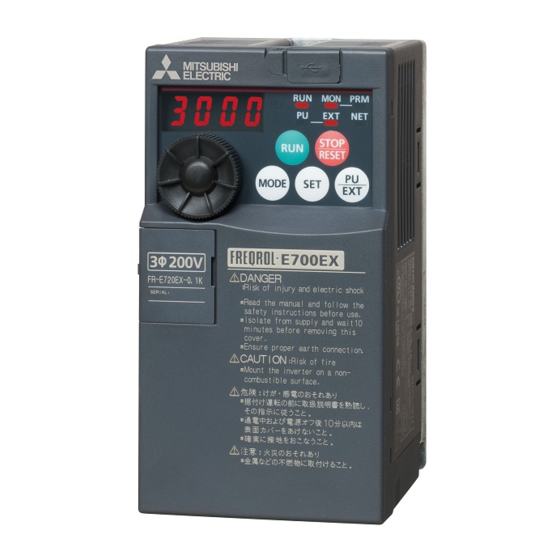
- Page 1 SENSORLESS SERVO FR-E700EX MM-GKR S e n s o r l e s s S e r v o Taking Drive Systems to New Places...
- Page 2 (PM sensorless vector control) without the use of an 95.0% encoder, facilitating the construction of highly reliable MM-GKR No encoder, (sensorless PM motor) 92.4% FR-E700 FR-A700 FR-E700EX MR-J4 90.0% drive systems capable of contributing to energy saving. ensuring even more SF-JR 89.9% compact size (induction motor) 85.0%...
- Page 3 S e n s o r l e s s S e r v o Full of easy-to-use functions Application examples Compact, high-performance drive unit Outstanding operability •Filling machines •Conveyors •Glass substrate Position Position Speed conveyance control control control •Operation is easy with the popular setting dial. (transfer conveyor) (ball screw) Speed and parameters can be set with frustration-free operability.
- Page 4 USB (Ver1. 1) cable. 200V class the capacity (kW). The breaker must be selected carefully Being RoHS compliant, the FR-E700EX series drive units Refer to page 25 Parameter setting and monitoring can be since an inrush current flows in the are friendly to people and to the environment.
- Page 5 Standard Specifications (FR-E700EX Series) Drive unit rating Three-phase 200V power supply Model FR-E720EX-K 0.75 Applicable motor capacity (kW) 0.75 Rated current (A) 150% 60s, 200% 3s Overload current rating (reference rated motor current, inverse-time characteristics) Rated input AC voltage/frequency...
-
Page 6: Operating Status
Drive unit common specifications Control method PM sensorless vector control (low-speed range: current synchronization operation) Carrier frequency 10kHz (when driving an MM-GKR series motor) Starting torque 200% (initial value) Initial magnetic pole Approx. 0.1s (performed at start, at SON/LX signal ON.) detection time Torque limit operation level Operation current level can be set (0 to 200% adjustable), whether to use the function or not can be selected. - Page 7 The following operating status can be displayed: rotation speed (output frequency), output current (steady), output voltage, speed setting value (frequency setting value), converter output voltage, regenerative brake duty, electronic thermal relay function load factor, output current peak value, Operating Operation converter output voltage peak value, output power, position pulse, cumulative energization time, panel status...
-
Page 8: Motor Rating
Standard Specifications (MM-GKR Series) Motor rating Motor model MM-GKR Compatible FR-E720EX-K 0.75 drive unit Power supply capacity (kVA) Continuous Rated output (kW) 0.75 Rated torque (N·m) 0.32 0.64 characteristic Maximum torque (N·m) 0.64 Rated speed (r/min) 3000 Maximum speed (r/min) 3000 Instantaneous permissible rotation speed 3450... -
Page 9: Specifications
MM-GKR series geared motor specifications Reduction-gear-equipped model for general industrial machines: G0 Permissible load Moment of Actual Output Reduction inertia moment Lubrication Installation inertia J Model reduction Mass(kg) ratio ratio method orientation ratio (10 kg·m (at motor shaft) 42/221 0.0720 1/12... - Page 10 Outline drawing of motors MM-GKR13 60.7 φ 4.5mounting hole. Use hexagonal 21.5 cap head bolts. Power connector 13.9 19.2 27.5 Signal Power supply 39.8 connector pin-outs name For the side opposite to the load (PE) Power connector 19.2 (Unit: mm) MM-GKR23, 43 φ...
- Page 11 Special shaft end specifications Motors with the following specifications (with dedicated shaft end) are available by request. D-cut shaft ...100W 21.5 20.5 (Unit: mm) Key shaft (with key) ...200W, 400W, 750W Section A-A (Unit: mm) Model M4 screw MM-GKR23K, 43K 14h6 Depth: 15...
- Page 12 MM-GKR series geared motor dimensions For reverse rotation command Rotation direction For forward rotation command φ Power connector Power supply Pin No. Signal name connector pin-outs (PE) (Unit: mm) Reduction ratio Model (Actual reduction ratio) (42/221) 1/12 112.7 60h7 16h6 48.5 91.7 34.5...
-
Page 13: Selection Criteria
Sensorless PM motors selection example (1) Selection criteria Configurations Feed speed of moving part = 30000 (mm/min) = ball screw diameter 20 (mm) Feed length per cycle = ball screw length 500 (mm) = 375 (mm) = gear diameter Positioning time = within 1 (s) 25 (mm) (motor shaft) -
Page 14: Connection Example
Terminal Connection Diagram (Speed Control) Connection example Sink logic ∗ 1. DC reactor (FR-HEL) Main circuit terminal When connecting a DC reactor, remove the jumper across P1 and P/+. Control circuit terminal Brake unit ∗6 A brake transistor is not built-in to the (Option) 0.1K and 0.2K. -
Page 15: Terminal Specifications
Terminal Specifications Terminal Type Terminal Name Description Symbol R/L1, S/L2, Connect to the commercial power supply. Keep these terminals open when using the high power AC power input factor converter (FR-HC2) or power regeneration common converter (FR-CV). T/L3 U, V, W Drive unit output Connect a PM motor. - Page 16 Terminal Type Terminal Name Description Symbol 1 changeover contact output indicates that the drive unit fault occurs. Relay output A, B, C Fault: discontinuity across B-C (continuity across A-C), Normal: continuity across B-C (discontinuity (fault output) across A-C) Contact capacity 230VAC 0.3A (power factor = 0.4) 30VDC 0.3A Permissible load 24VDC Switched Low when the drive unit rotation speed is equal to or (Maximum 27VDC) 0.1A (a...
- Page 17 Terminal Connection Diagram (Position Control) Connection example Sink logic ∗ 1 DC reactor (FR-HEL) 1. DC reactor (FR-HEL) Main circuit terminal When connecting a DC reactor, remove the When connecting a DC reactor, remove the jumper across P1 and P/+. jumper across P1 and P/+.
-
Page 18: Position Control
Position Control Position control specifications Item Specifications Positioning command input Point table method method Interface Input terminal selection, RS-485 communication, CC-Link communication (plug-in option) Number of points 7 points Command data -99999999 to 99999999 Command setting range method Command setting Absolute position command with sign, increment command with sign method Electronic gear... - Page 19 Point table method Set positioning parameters such as the number of pulses (position) and acceleration/deceleration time in advance to create a point table (point table method). Positioning operation is performed by selecting the point table. Operation example (absolute position command) Table selection Position data Auxiliary function...
- Page 20 Operation example (roll feed) The current position and position command are set to 0 at start, and then positioning operation is performed. Because the current position and position command are set to 0 at start, position commands are not overflowed and the repeated feed by the increment is available.
-
Page 21: Operation Panel
Operation Panel The operation panel cannot be removed from the drive unit. Operating status indication Operation mode indicator PU: ON to indicate PU operation mode. ON or flicker during drive unit EXT:ON to indicate External operation operation. mode. ON: When forward rotation (ON at power-ON at initial... - Page 22 Basic operation of the operation panel Operation mode switchover At power-ON (External operation mode) PU Jog operation mode (Example) PU operation mode Value change and speed flicker. (rotation speed monitor) Speed setting has been written and completed!! STOP Output current monitor Output voltage monitor Display the Parameter setting mode...
-
Page 23: Parameter Unit (Fr-Pu07)
Parameter Unit Parameter unit (FR-PU07) The parameter unit is a convenient tool for drive unit setting Description such as direct input with a numeric keypad, operation status Used for parameter setting. indication, and help function. Press to choose the parameter setting mode. ... - Page 24 FR Configurator is software offers an easy operating environment. It can be utilized effectively from drive unit setting up to maintenance. (Some functions of FR Configurator may not support the FR-E700EX.) Parameter setting, monitoring, etc. can be performed on a display of Windows personal computer.
-
Page 25: Parameter List
Parameter List For simple variable-speed operation of the drive unit, the initial setting of the parameters may be used as they are. Set the necessary parameters to meet the load and operational specifications. Parameter setting, change and check can be made from the operation panel. - Page 26 Minimum Initial Customer Function Parameter Name Setting Range Setting Value Setting Increments 0, 5, 8 to 12, 14, 19, 20, 23 to 31, DU/PU main display data selection 36, 37, 52 to 55, 61, 62, 100 1 to 3, 5, 8 to 12, 14, 21, 24, 36, FM terminal function selection 37, 52, 53, 61, 62 Speed monitoring reference...
-
Page 27: Function Parameter
Minimum Initial Customer Function Parameter Name Setting Range Setting Value Setting Increments 0 to 5, 7, 8, 10, 12, 14, 16, STF terminal function selection 23 to 25, 29, 30, 44, 60, 62, 65 to 67, 76, 86 to 89, 9999 0 to 5, 7, 8, 10, 12, 14, 16, STR terminal function selection 23 to 25, 29, 44, 60, 61, 65 to 67,... - Page 28 Minimum Initial Customer Function Parameter Name Setting Range Setting Value Setting Increments 0, 1, 3, 4, 7, 8, 11 to 16, 21, 24, DO0 output selection 9999 26, 33, 36, 38, 47, 55, 56, 60, 61, 63, 64, 90, 91, 93, 95, 96, 98, 99, 100, 101, 103, 104, 107, 108, DO1 output selection 9999...
- Page 29 Minimum Initial Customer Function Parameter Name Setting Range Setting Value Setting Increments Maintenance timer 0 (1 to 9998) Maintenance timer alarm output set time 0 to 9998, 9999 9999 Position detection hysteresis width 0 to 32767 Rough match output range 0 to 32767 Home position shift amount lower 4 digits 0 to 9999 Home position shift amount upper 4 digits 0 to 9999...
- Page 30 Minimum Initial Customer Function Parameter Name Setting Range Setting Value Setting Increments First positioning acceleration time 0.01 to 360s 0.01s First positioning deceleration time 0.01 to 360s 0.01s Second positioning acceleration time 0.01 to 360s 0.01s Second positioning deceleration time 0.01 to 360s 0.01s Third positioning acceleration time...
-
Page 31: Setting Range
Minimum Initial Customer Function Parameter Name Setting Range Setting Value Setting Increments FM terminal calibration — — — (900) Terminal 2 speed setting bias speed 0 to 4800r/min 1r/min 0r/min (902) Terminal 2 speed setting bias 0 to 300% 0.1% (902) ... -
Page 32: Protective Functions
Protective Functions When a fault occurs, the drive unit trips and the PU display automatically changes to one of the following fault or alarm indications. The error message shows an operational error. It does not trip the drive unit. Warnings are messages given before faults occur. It does not trip the drive unit. When a fault occurs, a protective function is activated to trip a drive unit and output a fault signal. -
Page 33: Option List
Option and Peripheral Devices Option list By fitting the following options to the drive unit, the drive unit is provided with more functions. One type of plug-in option can be mounted. Applicable Name Model Applications, Specifications, etc. drive unit This option allows the drive unit to be operated or monitored or CC-Link communication FR-A7NC E kit the parameter setting to be changed from a programmable... - Page 34 Applicable Name Model Applications, Specifications, etc. drive unit MR-PWS1CBLM- Power supply cable A1-H/A1-L/A2-H/A2-L (Servo motor connection Cable for connecting the drive unit and motor MR-PWS2CBL03M- cable) A1-L/A2-L Pilot generator QVAH-10 For tracking operation. 70V/35VAC 500Hz (at 2500r/min) For continuous speed control operation (mechanical deviation Deviation sensor YVGC-500W-NS detection).
- Page 35 Outline dimension and enclosure cut dimensions (Refer to page 7) (Note)1. The operation panel cannot be removed from the drive unit. 2. The separate parameter unit connection cable (FR-CB20) is required. Supports installation of FR-E700EX series on a DIN rail. Approximate dimension DIN rail mounting...
-
Page 36: Outline Dimension
Name (Model) Specifications, Structure, etc. When installed in the DC section of the drive unit, the DC reactor improves the power factor and suppresses the input side harmonic current. Selection method FR-HEL Select a DC reactor according to the applied motor capacity. ... -
Page 37: Specification
Name (Model) Specifications, Structure, etc. Outline dimension FR-BSF01 FR-BLF MCCB Drive unit Power R/L1 supply φ7 S/L2 2-φ5 Line noise filter T/L3 Line noise FR-BSF01 filter (Note)1. Each phase should be wound at least 3 times (4 turns) (for drive units with small in the same direction. - Page 38 Name (Model) Specifications, Structure, etc. Outline dimension Outline Dimension High-duty Brake Resistor Permissible Thermal Relay Type brake resistor Model Brake Duty (Mitsubishi Product) W1+20 FR-ABR-K FR-ABR-0.4K 140 500 TH-N20CXHZ-0.7A FR-ABR-0.75K 215 500 TH-N20CXHZ-1.3A (Note)1.The regenerative brake duty setting should be less than the permissible brake duty in the table above.
- Page 39 Name (Model) Specifications, Structure, etc. Enables 100%-torque continuous regeneration to support continuous regenerative operation for line control, etc. (Maximum torque 150% 60s) Eliminates the need to use a brake unit with each drive unit, reducing total space and total cost. ...
-
Page 40: List Of Cables And Connectors
The power supply cable MR-PWS3CBL_M-A_-L, which is a shielded cable, is also available. Please contact your sales representative. For unlisted lengths For unlisted lengths of the cables, contact Mitsubishi Electric System & Service Co., Ltd. FA PRODUCT DIVISION by email: oss-ip@melsc.jp Detailed model of option cables and connectors Model... - Page 41 Peripheral devices/cable size list Check the model name of the drive unit you purchased. Appropriate peripheral devices must be selected according to the capacity. Refer to the following list and prepare appropriate peripheral devices. Moulded Case Circuit Breaker (MCCB) Magnetic or Earth Leakage Current Breaker (ELB)...
- Page 42 Selecting the rated sensitivity current for the earth leakage current breaker When using the earth leakage current breaker with the drive unit Example circuit, select its rated sensitivity current as follows, independently of the PWM carrier frequency. Noise filter φ Drive ...
-
Page 43: Installation
Precautions for Operation/Selection Precautions for use of the drive unit Installation Avoid hostile environment where oil mist, fluff, dust particles, etc. are Safety Precautions suspended in the air, and install the drive unit in a clean place or put ... - Page 44 Precautions for the use of a sensorless Wiring PM motor Applying the commercial power supply to input terminals (U, V, W) of a sensorless PM motor will burn the sensorless PM motor. The SAFETY INSTRUCTIONS sensorless PM motor must be connected with the output terminals ...
- Page 45 Precautions for Peripheral Device Selection Installation and selection of Wire thickness and wiring distance moulded case circuit breaker When the wiring length between the drive unit and motor is long, use thick wires so that the voltage drop of the main circuit cable is 2% Install a moulded case circuit breaker (MCCB) on the power receiving or less especially at low speed output.
-
Page 46: Leakage Currents
Users who use models other than the target models are not covered Leakage currents by the guideline. However, we ask to connect an AC reactor or a DC reactor as before to the users who are not covered by the guideline. Capacitances exist between the drive unit I/O cables, other cables and For compliance to the harmonic suppression guideline for earth and in the motor, through which a leakage current flows. - Page 47 Major difference with the AC servo system AC servo Item Sensorless servo JN series J4 series Speed control Speed control Speed control Control mode Position control Position control Position control Torque control Torque control Encoder Without With With Required Not required because the Not required because the Initial magnetic pole detection (detection time: about 0.1s)
-
Page 48: Warranty
Warranty When using this product, please note the warranty described below. 1. Warranty period and coverage We will repair any failure or defect (hereinafter referred to as "failure") in our FA equipment (hereinafter referred to as the "Product") arisen during warranty period at no charge due to causes for which we are responsible through the distributor from which you purchased the Product or our service provider. - Page 49 [ Related Factory Automation Products ]...
- Page 50 Tianjin Office •German FA Center MITSUBISHI ELECTRIC EUROPE B.V. German Branch •India Pune FA Center •Guangzhou FA Center MITSUBISHI ELECTRIC INDIA PVT. LTD. Pune Branch MITSUBISHI ELECTRIC AUTOMATION (CHINA) LTD. Guangzhou Office •UK FA Center MITSUBISHI ELECTRIC EUROPE B.V. UK Branch •India Gurgaon FA Center...
-
Page 51: Safety Warning
Safety Warning To ensure proper use of the products listed in this catalog, please be sure to read the instruction manual prior to use. HEAD OFFICE: TOKYO BLDG., 2-7-3, MARUNOUCHI, CHIYODA-KU, TOKYO 100-8310, JAPAN L(NA)06080ENG-A(1310)MEE...