ABB NAL Series Installation And Operating Instructions Manual
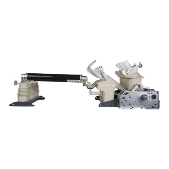
Indoor air switch-disconnector
Hide thumbs
Also See for NAL Series:
- Mounting and operation manual (32 pages) ,
- Mounting and operation manual (32 pages)

Related Manuals for ABB NAL Series


Summary of Contents for ABB NAL Series
- Page 1 — D I S T R I B U T I O N S O LU T I O N S Indoor Air Switch-disconnector, NAL/NALF/VR Installation and operating instructions 4.16 ... 38 kV / 200...1250 A...
- Page 3 — Table of contents 1.0 Your safety first – always! 1.1 General notes 1.2 Application highlights 2.0 Indoor air switch- disconnector 3.0 Introduction 3.1 Main product features 4.0 Environmental protection program 5.0 Safety instructions 6.0 Recommendations for receipt, handling and storage of equipment 6.1 Switch-disconnector type NAL/NALF/VR, alternative...
-
Page 4: Table Of Contents
M O U N T I N G A N D O P E R AT I O N M A N U A L I N D O O R A I R S W I TC H - D I S C O N N E C TO R , N A L / N A L F/ V R —... - Page 5 17.2 Motor drive settings for 21.0 Replacement of parts in A-mechanism NAL/VR 36 kV 17.3 Motor drive settings for 21.1 Replacement of contact K-mechanism knives 17.4 UEMC 41 21.2 Replacement of draw bar. Fig. 116 18.0 Service and maintenance 21.3 Replacement of the 18.1 Cleaning supporting insulator.
- Page 6 In case of any uncertainty or questions related to during installation. mounting and/or operation which are not Operations describe in this manual shall be described in the manual please contact ABB. carried out by specialists only. According to IEC 62271-1 p. 5.12 and IEC 1.1 General notes: 62271-102 p.
- Page 7 Reduction of which is a big advantage. space and installation requirements has ABB recommends to verify the position of already influenced the design of kiosks and the main knives before and after each stations however the proper maintenance is operation.
- Page 8 In combination with ABB CEF current limiting fuses, they provide reliable control over the full range of overload currents.
- Page 9 — 3.0 Introduction The NAL/NALF/VR switch-disconnector system is 3.1 Main Product Features based on a modular principle. The basic unit NALF/VR is the ideal solution for the protection consists of a frame with insulators and current of the majority of faults in modern electrical carrying elements.
- Page 10 M O U N T I N G A N D O P E R AT I O N M A N U A L I N D O O R A I R S W I TC H - D I S C O N N E C TO R , N A L / N A L F/ V R —...
- Page 11 • Always follow these instructions closely. • If you have any questions or doubts, please contact the proper ABB personnel. • Only original parts provided by PLABB should be used.
- Page 12 - NAL-H – IEC standard as line switch- validated in the order confirmation by ABB. disconnectors for harsh operating conditions. If immediate installation is not possible, please - NALF-H – IEC standard as switch-fuse store covered indoors, in a well-ventilated, dry, combination for harsh operating conditions.
- Page 13 This will prevent the stress contact grease (recommended grease: ISOFLEX forces in the switch frame When TOPAS NCA 52). ABB recommends to install this inequalities of surface are significant, use switch-disconnector in applications where it is a rigid support structure, e.g. made by possible to visually check main knives position ABB.
- Page 14 M O U N T I N G A N D O P E R AT I O N M A N U A L I N D O O R A I R S W I TC H - D I S C O N N E C TO R , N A L / N A L F/ V R For construction of the supporting structure it is recommended to use some U-iron or angle iron components.
- Page 15 — 8.0 Cable connections to NAL/F terminals WARNING Improper installation of cable connections to the switch-disconnector terminals cause an operational hazard. 8.1 How to install the medium voltage cable lug? — — 3 Proper cable lug connection 2 Proper cable lug connection Cable lugs should always be placed on the upper side of the switch terminal and face up (Fig.4).
- Page 16 M O U N T I N G A N D O P E R AT I O N M A N U A L I N D O O R A I R S W I TC H - D I S C O N N E C TO R , N A L / N A L F/ V R The connection bolt should be arranged such that one wrench can be used to hold the bolt head on the bottom and another can be used to tighten...
- Page 17 Cable lug installation on the incorrect side of the switch terminal. Cable lug cannot be fixed from the terminal lower side. Fix it as shown on Fig.3. — 11 Example of incorrect cable lug side installation Cable lug installation on the incorrect side of the switch terminal.
- Page 18 M O U N T I N G A N D O P E R AT I O N M A N U A L I N D O O R A I R S W I TC H - D I S C O N N E C TO R , N A L / N A L F/ V R —...
- Page 19 1. Take out the NAL/VR from the box. Open the contact knives to maximum position and connect the drawbars (disconnected for transport) with shaft. Install NAL/VR on support construction in open position, see Fig.13. — 13 NAL in open position 2.
- Page 20 M O U N T I N G A N D O P E R AT I O N M A N U A L I N D O O R A I R S W I TC H - D I S C O N N E C TO R , N A L / N A L F/ V R 4.
- Page 21 — — 19 Front bearing of hand operating mechanism HE 20 Take out the Seeger ring, spring and nut — — 21 Slide out the arrestor ring from the shaft 22 The shaft should loosely rotate loosely after taking out the arrestor ring —...
- Page 22 M O U N T I N G A N D O P E R AT I O N M A N U A L I N D O O R A I R S W I TC H - D I S C O N N E C TO R , N A L / N A L F/ V R —...
- Page 23 — — 27 Slide out the arrester ring to the position where it is possible 28 Check if the arrestor ring and switch- disconnector to turn the handle clockwise and close switch-disconnector are in locking position — — 29 If NOT (as in picture 22) slide out the arrestor ring 30 Correctly position the arrestor ring in closed from the shaft and turn 2-3 teeth to the right position...
-
Page 24: Adjustment Of The Hand Operating, Mechanism Type He
M O U N T I N G A N D O P E R AT I O N M A N U A L I N D O O R A I R S W I TC H - D I S C O N N E C TO R , N A L / N A L F/ V R —... -
Page 25: A-Mechanism. Fig
10.3 A-mechanism. Fig. 33 Current knives rotate with great speed and force. Always keep a safe distance from moving parts of the switch. Be careful especially with type A (dou- ble spring) mechanism. This kind of drive stores great energy and can release it by small rotation of shaft. -
Page 26: Hand Operating Mechanism Nemd
M O U N T I N G A N D O P E R AT I O N M A N U A L I N D O O R A I R S W I TC H - D I S C O N N E C TO R , N A L / N A L F/ V R —... -
Page 27: Design And Principle Of Operation
11.4 Design and principle of operation The NEMD drive consists of: operating lever, front lever, insulated rod, sliding mechanism. 11.5 Versions available • 1YMX888739M0001 - NEMD drive for NAL switch disconnector designed for mounting on the front wall of application panel. •... -
Page 28: Replacing The Mechanism On The Switch
Title Scale Location Date Name Language Drawn Subtitle Checked Format Approved ABB Switzerland Ltd Drawing No. Sheet No. 1 / 1 — — Group Technology Management 37 Shunt trip mounted on the A-mechanism 38 Mounting the mechanism on the switch... -
Page 29: Test Operation Of A-Mechanism
When the switches have to be operated from the — 39 Shaft extension for the left-hand side operation left side, an operating shaft must be connected, see Fig. 36. The mechanism clutch is brought together with the clutch of the hollow main shaft and the mechanism is fixed to the frame. -
Page 30: Mounting Of Fuse-Base
M O U N T I N G A N D O P E R AT I O N M A N U A L I N D O O R A I R S W I TC H - D I S C O N N E C TO R , N A L / N A L F/ V R —... -
Page 31: Mounting Of The Fuse Tripping. Fig
15 14 13 1 2 3 4 MEC. — — 46 A-mechanism 45 Fuse tripping completed 13.2 Mounting of the fuse tripping. Fig. 45 13.4 Fuse tripping Lower part of bearing (8) is fixed to terminal Turn the operating mechanism shaft (10) by one screw (9). -
Page 32: Mounting Of Earthing Switch Type E
M O U N T I N G A N D O P E R AT I O N M A N U A L I N D O O R A I R S W I TC H - D I S C O N N E C TO R , N A L / N A L F/ V R —... -
Page 33: Mounting The Earthing Switch To The Fuse- Switch Disconnector Type Nalf/Vr
14.3 Mounting the earthing switch to the fuse- switch disconnector type NALF/VR Proceed according to item “Mounting the earthing switch to the switch- disconnector type WARNING! NAL/VR”. The contacts A must be mounted on the By default earthing switch is configured to terminals of the fuse-base, and secured in be operated on the right hand operating position with tension. -
Page 34: Mounting The Shunt Release
M O U N T I N G A N D O P E R AT I O N M A N U A L I N D O O R A I R S W I TC H - D I S C O N N E C TO R , N A L / N A L F/ V R —... -
Page 35: Mounting The Auxiliary Switch
— 16.0 Mounting the auxiliary switch 16.1 Auxiliary switch for switch-disconnector. Electrical signalling of switch-disconnector Note: The minimum cross-section of the open/closed can be obtained with a group of wires used for the auxiliary circuits must 2NO+2NC, 4NO+4NC, 8NO+8NC auxiliary not be less than the one used for the ex- contacts. - Page 36 M O U N T I N G A N D O P E R AT I O N M A N U A L I N D O O R A I R S W I TC H - D I S C O N N E C TO R , N A L / N A L F/ V R —...
-
Page 37: Mounting The Auxiliary Switch For E-Eb Earthing Switch. Fig
— — 58 Wiring diagram auxiliary switch 59 Wiring diagram tripping coil 16.2 Mounting the auxiliary switch for E-EB earthing switch Fig. 60-71. Electrical signalling of earthing switch open/ closed can be obtained with a group of 2NO+2NC, 4NO+4NC auxiliary contacts. The auxiliary switch is mounted to the frame on the right side of the earthing switch and connected to the main shaft. - Page 38 M O U N T I N G A N D O P E R AT I O N M A N U A L I N D O O R A I R S W I TC H - D I S C O N N E C TO R , N A L / N A L F/ V R —...
-
Page 39: Mounting The Auxiliary Switch For Fuse Interruption
— — 69 Verify the correct operation of auxiliary switch 68 Tighten the holdfast screw rather firmly — — 70 Earthing switch in open position 71 Earthing switch in closed position 16.3 Mounting the auxiliary switch for fuse interruption The open fuse auxiliary switch can only be installed on the A-mechanism and a fuse base equipped with fuse tripping. - Page 40 M O U N T I N G A N D O P E R AT I O N M A N U A L I N D O O R A I R S W I TC H - D I S C O N N E C TO R , N A L / N A L F/ V R Bolt the open fuse auxiliary switch to the mounting hole on the A-mechanism and loosely install the screw hardware to allow the switch to...
- Page 41 Rotate the switch out of position and remove the white disk. Install the long bolt and two nuts into the marked hole from the previous step as in figure 76. — Re-install the white disk and switch back onto the A-mechanism.
-
Page 42: Mounting The Open Fuse Auxiliary Switch On Motor Bracket
M O U N T I N G A N D O P E R AT I O N M A N U A L I N D O O R A I R S W I TC H - D I S C O N N E C TO R , N A L / N A L F/ V R 16.4 Mounting the open fuse auxiliary switch on motor bracket Remove the two screws that secure the switch to... - Page 43 Install the provided screw and nuts into the marked hole from the previous step as shown in figure 82. — Rotate the white plastic disc, shown in figure 83, to its maximum displacement and listen for a “click”. This indicates that the switch will make contact.
-
Page 44: Motor Drive
M O U N T I N G A N D O P E R AT I O N M A N U A L I N D O O R A I R S W I TC H - D I S C O N N E C TO R , N A L / N A L F/ V R —... -
Page 45: Motor Drive Settings For A-Mechanism
17.2 Motor drive settings for A-mechanism — — 87 HE lower part for motor operation (a) and manual operation 86 Check that the motor drive is working correctly (b). There is also possibility to add blocking coil (b). 1. Check that the motor drive is working correctly —... - Page 46 M O U N T I N G A N D O P E R AT I O N M A N U A L I N D O O R A I R S W I TC H - D I S C O N N E C TO R , N A L / N A L F/ V R —...
-
Page 47: 17.3 Motor Drive Settings For K-Mechanism
17.3 Motor drive settings for K-mechanism — — 95 NAL 12 in open position 96 NAL 12 in open position NAL/NALF/VR must be in open position. Locate the spacer bracket mounting holes on the K-mechanism. Fully tighten mounting screws. See Fig. 95, 96. —... -
Page 48: Uemc
M O U N T I N G A N D O P E R AT I O N M A N U A L I N D O O R A I R S W I TC H - D I S C O N N E C TO R , N A L / N A L F/ V R 17.4 UEMC 41 The UEMC 41 - motor operating devices are intended for indoor mounting on medium voltage... -
Page 49: Service And Maintenance
If fuses were applied to the switch they must be replaced. The proper coordination with the NALF switch-fuse combination requires fuse selection from Reference list of fuses (see 24.0) according to ABB instruction. -
Page 50: Mechanical Overhaul
Mechanical overhaul of the switch-disconnector should be carried out after max. 1000 operations or 15 years in service, (preferably by ABB’s staff). CAUTION! During switch-disconnector exploitation, position of main contact may change (parts wear) but it cannot be... -
Page 51: Control Of Nal/Vr Knives After Mounting. Fig
105 Open and close position of switch- disconnector with earthing switch Material Weight Surface code Surface Type Derived from Drawing status Revision EC No. Responsible Title PLABB Location Date Name PL-PSY M. Mańkowski Drawn Subtitle Checked Approved ABB Switzerland Ltd Drawing No. Group Technology Management... - Page 52 M O U N T I N G A N D O P E R AT I O N M A N U A L I N D O O R A I R S W I TC H - D I S C O N N E C TO R , N A L / N A L F/ V R Switch with A-mechanism.
- Page 53 110 Illustrative drawing of eccentric bolt adjustment. Material Weight Surface code Surface Type Derived from Drawing status Revision EC No. Responsible Title Scale PLABB Location Date Name Language PL-PSY M. Mańkowski Drawn Subtitle Checked Format Approved ABB Switzerland Ltd Drawing No. Sheet No.
-
Page 54: Replacement Of Parts (12-24 Kv)
M O U N T I N G A N D O P E R AT I O N M A N U A L I N D O O R A I R S W I TC H - D I S C O N N E C TO R , N A L / N A L F/ V R —... -
Page 55: Replacement Of Contact Knife With Draw Bar. Fig.110
Fig. 111 WARNING! WARNING! These operations shall be carried out by These operations shall be carried out by authorised ABB service only! authorised ABB service only! Material Weight Switch-disconnector in open position with both Detach the main contact with contact knives 22.86 kg... -
Page 56: Replacement Of Fixed Contact On The Opening Side Fig
ISOFLEX TOPAS NCA WARNING! These operations shall be carried out by 19.4 Replacement of the arcing chamber. Fig. 112 authorised ABB service only! Follow instructions under item „Replacement of fixed contact on the opening side”. Switch-disconnector in open position: Unscrew the two screws 3.1 and lift up the... -
Page 57: Replacement Of Insulators
Any unauthorized use, reproduction, distribution or disclosure to third parties ABB Switzerland Ltd Drawing No. Sheet No. is strictly forbidden. ABB reserves all rights regarding Intellectual Property Rights. 1YMX000271M0136 ISO 2768 T.1 Lengths and Angle Thread Quality Tolerance 1 / 1 "6g-6H"... -
Page 58: 21.0 Replacement Of Parts In Nal/Vr 36 Kv
21.0 Replacement of parts in NAL/VR 36 kV 21.1 Replacement of contact knives WARNING! These operations shall be carried out by authorised ABB service only! Disconnect the switch-disconnector. When A-mechanism is fitted, the opening spring must NOT be charged. —... -
Page 59: Replacement Of Draw Bar
21.2 Replacement of draw bar. Fig. 117 WARNING! These operations shall be carried out by authorised ABB service only! Disconnect the switch-disconnector. Pull out the bolt b. Pull down the auxiliary knife such that the — drawbar bolt (a) can be pushed out and upper 118 Contact knife hold for the drawbar is free. -
Page 60: Replacement Of The Hollow Insulator. Fig
M O U N T I N G A N D O P E R AT I O N M A N U A L I N D O O R A I R S W I TC H - D I S C O N N E C TO R , N A L / N A L F/ V R 15 Nm WARNING! These operations shall be carried out by authorised ABB service only! 21.4 Replacement of the hollow insulator. Fig. Disconnect the switch-disconnector. The spring mechanism is removed from the frame. -
Page 61: 22.0 Adjustment Of Splined Shaft End For Earthing Switch
— 22.0 Adjustment of splined shaft end for earthing switch. Fig. 123- 127. CAUTION! In case of changing the operating side of earthing switch (and mechanical — interlocking), splined shaft end location 123 Remove the retaining ring [1] and washer [2] should be updated accordingly. -
Page 62: Liabilities
M O U N T I N G A N D O P E R AT I O N M A N U A L I N D O O R A I R S W I TC H - D I S C O N N E C TO R , N A L / N A L F/ V R — 23.0 Liabilities The liability of ABB with respect to any and all claims arising out of the performance or non-performance of obligations connected with... -
Page 63: Reference List Of Fuses
— 24.0 Reference list of fuses The reference list of fuse -links for NALF/VR switch-fuse combinations according to IEC 62271-105 ABB CEF/CEF-VT fuse-link selection for transformer protection with load 100% and 120% Transformer Fuse-link Rated Switch-fuse Relative Rated system combination... - Page 64 M O U N T I N G A N D O P E R AT I O N M A N U A L I N D O O R A I R S W I TC H - D I S C O N N E C TO R , N A L / N A L F/ V R Transformer Fuse-link Rated...
- Page 65 Transformer Fuse-link Rated Switch-fuse Relative Rated system combination Rated impedance Rated Rated Rated normal voltage dedicated power S voltage current I current I voltage current Length [kV] type [kVA] uk [%] [A] 100% [A] 120 % Type [kV] e [mm] Catalogue number 1.40 1.68...
- Page 66 M O U N T I N G A N D O P E R AT I O N M A N U A L I N D O O R A I R S W I TC H - D I S C O N N E C TO R , N A L / N A L F/ V R Reference list for ABB CEF-S fuse-link selection for transformer protection with 100% and 120 % load...
- Page 67 Reference list for fuse-link CEF-S/CEF selection for the transformer protection for Swedish market with 100% and 120 % load (§17; fuse with cut off time within 0,1 seconds “Sverigesäkring”) Transformer Fuse-link Rated Switch-fuse Relative Rated system combination Rated impedance Rated Rated Rated normal...
-
Page 68: Environmental Declaration
25.0 Environmental declaration 25.1 Environmental Certification Life 25.2 End-of-life expectancy of product ABB is committed to the protection of the The product is developed in compliance with the environment and adheres to ISO 14001 standards. requirements denoted by IEC 62271-200. The... - Page 69 Acetone Ethylamine, 33% Acrylonitrile Ethylene diamine Allyl alcohol Ethylene glycol Ammonium sulfide, 40% Fluorodichloromethane WARNING! Amyl alcohol Formic acid, concentrated The apparatus can not work or have Aniline Furfuralcohol contact with hazardous chemicals for Benzaldehyde Gasoline (5% methanol) materials mentioned in table above. Benzoic acid Glacial acetic acid Bromine, liquid...
- Page 70 With regard to purchase orders, the agreed particulars shall prevail. ABB AG does not accept any responsibility whatso- ever for potential errors or possible lack of information in this document.
- Page 72 ABB Sp. z o.o. Branch in Przasnysz 59 Leszno Str. 06-300 Przasnysz, Poland Phone: +48 22 22 38 900 Fax: +48 22 22 38 953 www.abb.pl © Copyright 2020 ABB. All rights reserved. Specifications subject to change without notice.