ABB NAL Series Mounting And Operation Manual
Indoor air switch-disconnector
Hide thumbs
Also See for NAL Series:
- Installation and operating instructions manual (72 pages) ,
- Mounting and operation manual (32 pages)
Table of Contents
Advertisement
Mounting and operation manual
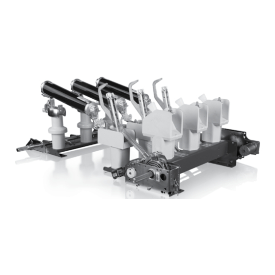
Indoor Air Switch-disconnector, NAL/NALF/VR
Rated voltage: 12, 17.5, 24 and 36 kV
Rated current: 400/630, 800 and 1250 A
The NAL/VR family of switch-disconnectors is characterized
by its compact, modular design and broad functionality. With
their unique design for extinguishing the electric arc and high
switching capacity, they represent an attractive solution, as main
switching apparatus for applications in enclosed switchgear and
compact transformer stations. In combination with CEF current
limiting fuses, they provide reliable control over the full range of
overload currents.
Main areas of application NAL/VR switch disconnectors:
– as line and transformer switches within distribution networks,
– as motor switches,
– as capacitor switches.
Introduction
The NAL/NALF/VR switch-disconnector system is based on a
modular principle. The basic unit consists of a frame with insulators
and current carrying elements. Two different types of operating
mechanisms: snap action mechanism type K or stored spring energy
mechanism type A, can be mounted on the frame. Fuse bases type F
with or without fuse tripping mechanism, and earthing switch type E/
EB, suitable for both direct monting and free standing components,
complete the basic switch-disconnector equipment. These modules
can be easily configured, according to customer requirements.
Accessories such as shunt trip, auxiliary switches, motor operation
and various systems for manual operation can easily be added.
The NAL/NALF/VR brand is recognised globally and more than
600,000 switches have been produced so far. The design is subject to
continuous development to meet changing customer needs.
Main Product Features
NALF/VR is the ideal solution for the protection of the majority of faults
in modern electrical networks. It combines NAL/VR, which interrupts
load currents (up to 1250A) and small fault currents, with the fuse base
(F) for breaking large short-circuit currents.
This switch-disconnector range meets IEC Publication 60129, 60265,
60694, GOST 1516.3-96, GOST 17717-79, and CSA Standard No.
C22.2, No. 193, and IEC 62271-105, regarding switches for general
use and for safe switching coordination between switch-disconnectors
and a current limiting fuse.
The NAL version for ANSI standard is called VersaRupter. It meets ANSI
Standard No. C37.20.4.
The specified NAL/NALF switch-disconnectors are listed as certified by
the Canadian Standard Association. Some VersaRupter styles are UL
listed, in terms of compliance with relevant safety requirements, in order
of their release for use in each region of the US and installations carried
out in accordance with the UL standard.
Advertisement
Table of Contents

Related Manuals for ABB NAL Series


Summary of Contents for ABB NAL Series
- Page 1 Mounting and operation manual Indoor Air Switch-disconnector, NAL/NALF/VR Rated voltage: 12, 17.5, 24 and 36 kV Rated current: 400/630, 800 and 1250 A The NAL/VR family of switch-disconnectors is characterized by its compact, modular design and broad functionality. With their unique design for extinguishing the electric arc and high switching capacity, they represent an attractive solution, as main switching apparatus for applications in enclosed switchgear and compact transformer stations.
- Page 2 Your safety first – always! That’s why our instruction manual begins with these recommendations: – Comply in full with the legally recognized standards (ANSI / IEC), the connection conditions of the local electrical utility and the applicable safety at work regulations. WARNING! –...
-
Page 3: Table Of Contents
Triple-pole switch-disconnector type NAL/VR and fuse switch-disconnector type NALF/VR for indoor installation Safety instructions .............4 20.2 Changing draw bar ............27 Recommendations for receipt, handling and storage of 20.3 Changing the supporting insulator ........28 equipment ................4 20.4 Changing the hollow insulator ..........28 Switch-disconnector type NAL/VR, alternative assemblies .4 20.5 Changing the piston with piston rod ........29 Installation .................4... -
Page 4: Safety Instructions
3.1 Fully assembled with mechanism and auxiliaries. See item 4.0 When inequalities of surface are significant, use a rigid support 3.2 Switch main frame, mechanism and auxiliaries as separate structure, eg made by ABB. components, see item 6.0 i 7.0 Fig. 1 Switch-disconnector type NAL/VR... -
Page 5: Preparation Of The Supporting Structure
Fig. 2 Switch-disconnector type NAL/VR with K-mechanism Fig. 3 Switch-disconnector type NAL/VR with A-mechanism 4.2. Preparation of the supporting structure During installation be careful and do not apply too big torque on The disconnectors are intended for vertical or horizontal operations. the insulators. -
Page 6: Mounting The Mechanism On The Switch
Opening The mechanisms are mounted on the right hand side of the switch Pull out arrester ring S and turn the operating handle main frame and the switch is normally operated from the same anti-clockwise. The switch opens after approx. 20° rotation. side (mechanism-side). -
Page 7: Test Operation Of A-Mechanism
6.1. Test operation of A-mechanism 7.1 Instruction of installation and adjustment of switch di- After having mounted the mechanism to the switch frame, check sconnector type NAL/NALF/VR with hand operation mecha- that the latch H is in correct position by pulling it back to the nism HE. - Page 8 4. Install the hand operation type HE. Between cardanic joint and 6. Slide out the arrestor ring from the shaft, see Fig. 15. bevel gear. Put the connection rod (pipe =26.9 mm) between 7. The shaft should loosely rotate loosely after taking out the the cardanic joint and the bevel gear.
- Page 9 9. A mechanism opening spring is charged, see Fig. 18. 11. Put the arrestor ring on the shaft, see Fig. 20. 10. Turn the handle to the left and right for test, see Fig. 19. 12. Slide out the arrester ring to the position where it is possible to turn the handle clockwise and close disconnector, see Fig.
- Page 10 13. Check if the arrestor ring and switch disconnector are in 16. Check the opening spring is charged. After adjustment the locking position, see Fig. 22. Seeger ring, spring and nut should be put back on the HE 14. If NOT (as in picture 22) slide out the arrestor ring from the shaft, see Fig.
-
Page 11: Mounting Of Fuse Base
8.0 Mounting of fuse base 2. The lever (13) together with the fuse trip flap (15) are placed in the lower bearing (8) and locked by means of upper part of WARNING bearing (14). These operations can be carried out by 3. -
Page 12: Adjustment Of The Fuse Tripping
(DIN 43625) the tapped connection is free from disc (3). link then will have the same dimensions as ABB-CEF fuse-links, 3–6 mm 2. The release rod (1) with the drive ring (2) is turned and ajusted 3. -
Page 13: Mounting Of Eartch Switch Type E And Eartch Switch
9.0 Mounting of earth switch type E (Fig. 32) and earth switch 9.2 Mounting the earth switch to the fuse-switch type LCES (Fig. 33) disconnector type NALF/VR The switch will normally be delivered for connection of the hand Proceed as under item 7.1. The contacts A must be mounted operating mechanism on the right hand side and any mechanical on the terminals of the fuse base, and secured in position with interlook on the left side. -
Page 14: Mounting The Shunt Release
Testing the interlock Return the shaft to its neutral position. Connect the bar to the per- It shall not be possible to close the switch-disconnector when the forated disc (see Fig 38) in such a way that it does not block the earth switch is closed. mechanism and work properly. -
Page 15: Mounting The Auxiliary Switch For E-Eb Earthing Switch, Excluding Lces
13.0 Mounting the auxiliary switch for E-EB earthing switch, 3. Holdfast screw must be tightened from the flat side of auxiliary switch shaft, see Fig. 42. excluding LCES, Fig. 40-50. 1. The installation starts with the earthing switch in open position, see Fig. - Page 16 4. The shackle (connecting part with a hole) is mounted on the 5-7. Tighten the screws (M5) that mount the shackle on extension shaft of earthing switch so that the rod connecting extension shaft of earthing switch, see Fig. 44-46. the arm of auxiliary switch with shackle is slightly strained, see Fig.
- Page 17 8-9. Tighten the holdfast screw rather firmly, see Fig. 47-48. Verify the correct operation of auxiliary switch. 10. Earthing switch in open position, see Fig. 49. 11. Earthing switch in closed position, see Fig. 50. Fig. 47-50 Mounting the auxiliary switch for E-EB earthing switch Fig.
-
Page 18: Mounting Of Nm Motor Drive
14.0 Mounting of NM/MU motor drive Motor drive settings for A-mechanism 1. Check that the motor drive is working correctly according to 2. NAL/VR/F must be in open position and discharge both Fig. 51 and 52. springs. Locate the spacer bracket mounting holes on the A- -mechanism, see Fig. - Page 19 3. To reduce side shake, turn the operating shaft anticlockwise, see Fig. 55-56. 4. Before mounting on the A-mechanism shaft, set up distance to ~4-8 mm, see Fig. 57. Fig. 55-57 Mounting of NM/MU motor drive on A-mechanism Fig. 55 Fig.
- Page 20 5. Mount the standard motor drive for NAL/VR/F on the shaft and fully tight mounting screws, see Fig. 58-59. Fig. 58-59 Mounting of standard motor drive for NAL/VR/F on A-mechanism Fig. 58 Fig. 59 20 NAL/NALF/VR – Mounting and operation manual...
- Page 21 Motor drive settings for K-mechanism. 8. Before mounting the motor device, adjust distance ~3-5 mm 6. NAL/VR/F must be in open position. Locate the spacer brac- in K-mechanism, see Fig. 63. ket mounting holes on the K-mechanism, see Fig. 60-61. 9.
-
Page 22: Service And Maintenance
Complete overhaul of the switch disconnector should be car- tions, ried out after 1000 operations or 5 (15 for new version switch- es) years in service, preferably by ABB’s staff. Note! Arcing knives, piston and cylinder must not be greased. Electrical overhaul The frequency of overhaul depends also on the number of operations and the magnitude of the breaking current. - Page 23 Control of NAL/VR knives after mounting Fig. 66-68 Due to possible differences in the straightness of the wall and support frame, it is necessary to check the position of the main knives on the fixed contact. 1. Switch with A-mechanism. On delivery the draw bars (1.1) are detached, a) test by hand that each arcing knife (1.2) moves freely in the arc chamber (1.3),...
-
Page 24: Replacement Of Parts (12-24 Kv)
16.0 Replacement of parts (12-24 kV) 16.1 Replacement of contact knife with draw bar Fig. 69. Switch-disconnector in open position with both the operating WARNING springs uncharged: These operations can be carried out by 1. Remove the circlips 2.1 attaching the draw bar to the main specialists only! shaft (eccentric bolt not to be loosened). -
Page 25: Replacement Of Fixed Contact On The Opening Side
16.2 Replacement of fixed contact on the opening side Fig. Switch-disconnector in open position: 1. Unscrew the two screws 3.1 and lift up the arcing chamber and the thermal disc 3.4 (for 630 A) while pressing the main contact 3.5 firmly against the hollow insulator 3.8. 2. -
Page 26: Insulator For Fusebase And Quick Make Earthing Switch
19.0 Insulator for fusebase and quick make earthing switch Fig. 72 1. Unscrew 4.2 and detach the fuse clips and contact block respectively. 2. Unscrew 4.3 at the base of the insulator and detach the insulator. 3. Attach the new insulator to the frame by the two self-tapping screws 4.3. -
Page 27: Changing Draw Bar
2. The contact screw is detached and the contact knives are removed, see Fig. 74. 3. Replacement contact knifes are lubricated with ISOFLEX TO- PAS NCA 52 and fited to the contact block with the contact screw. 4. Check that the contact knives can move easily and operate correctly over the opposite contacts. -
Page 28: Changing The Supporting Insulator
20.3 Changing the supporting insulator. Fig. 76 6. Undo the fixing screws on insulator. 1. Disconnect the switch-disconnector. 7. The hollow insulator is attached to the frame by 4 screws 2. Contact block with contact knives is dismounted (use span- M10 (spannergap 17). -
Page 29: Changing The Piston With Piston Rod
20.5 Changing the piston with piston rod. Fig. 78 21.0 Liabilities NB! Remove spring mechanism before starting. If a mechanism The liability of ABB with respect to any and all claims arising out of is installed. the performance or non-performance of obligations connected 1. -
Page 30: Reference List Of Fuses
22.0 Reference list of fuses Discon- Type of Rated Rated Length Diameter These fuse links has been tested, according to IEC nector fuse links voltage current [A] [mm] [mm] Un [kV] 62271-105 with air switch-disconnector Type NALF/VR 3.6/7.2 192/292 3.6/7.2 192/292 WARNING 3.6/7.2... -
Page 31: Environmental Declaration
25 years (IEC NAL/VR36-6A360 – 72 kg 62271-200). End-of-life ABB is committed to the protection of the environment and adheres to ISO 14001 standards. It is our obligation to facilitate end-of life-recycling for our products. Raw Material % of total weight... - Page 32 We reserve the right to make technical changes or modify the For more information please contact: contents of this document without prior notice. With regard to purchase orders, the agreed particulars shall prevail. ABB ABB Contact Center does not accept any responsibility whatsoever for potential errors tel.: +48 22 22 37 777...