ABB NAL Series Mounting And Operation Manual
Indoor air switch-disconnector
Hide thumbs
Also See for NAL Series:
- Mounting and operation manual (32 pages) ,
- Installation and operating instructions manual (72 pages)
Table of Contents
Advertisement
Quick Links
- 1 Switch-Disconnector Type Nal, Alternative Assemblies
- 2 Preparation of the Switch for Installation
- 3 K-Mechanism
- 4 Adjustment of the Hand Operating, Mechanism Type He
- 5 Service and Maintenance
- 6 Technical Specification for Nal/Nalf Switch Disconnectors Nal 12 - 17.5 - 24 - 36/6 - 12.5 a - K
- Download this manual
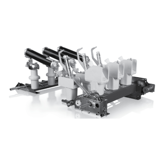
Mounting and operation manual
Indoor Air Switch-disconnector, NAL/NALF
Rated voltage: 12, 17.5, 24 and 36 kV
Rated current: 400/630, 800 and 1250 A
The NAL family of switch-disconnectors is characterized
by its compact, modular design and broad functionality. With
their unique design for extinguishing the electric arc and high
switching capacity, they represent an attractive solution, as main
switching apparatus for applications in enclosed switchgear and
compact transformer stations. In combination with CEF current
limiting fuses, they provide reliable control over the full range of
overload currents.
Main areas of application NAL switch disconnectors:
– as line and transformer switches within distribution networks,
– as motor switches,
– as capacitor switches.
Introduction
The NAL/NALF switch-disconnector system is based on a modular
principle. The basic unit consists of a frame with insulators
and current carrying elements. Two different types of operating
mechanisms: snap action mechanism type K or stored spring energy
mechanism type A, can be mounted on the frame. Fuse bases type F
with or without fuse tripping mechanism, and earthing switch type E/
EB, suitable for both direct monting and free standing components,
complete the basic switch-disconnector equipment. These modules
can be easily configured, according to customer requirements.
Accessories such as shunt trip, under-voltage release, auxiliary
switches, motor operation and various systems for manual operation
can easily be added.
The NAL/NALF brand is recognised globally and more than 600,000
switches have been produced so far. The design is subject to
continuous development to meet changing customer needs.
Main Product Features
NALF is the ideal solution for the protection of the majority of faults in
modern electrical networks. It combines NAL, which interrupts load
currents (up to 1250A) and small fault currents, with the fuse base (F)
for breaking large short-circuit currents.
This switch-disconnector range meets IEC Publication 60129, 60265,
60694, GOST 1516.3-96, GOST 17717-79, and CSA Standard No.
C22.2, No. 193, and IEC 62271-105, regarding switches for general
use and for safe switching coordination between switch-disconnectors
and a current limiting fuse.
The NAL version for ANSI standard is called VersaRupter. It meets
ANSI Standard No. C37.20.4.
The specified NAL/NALF switch-disconnectors are listed as certified by
the Canadian Standard Association. Some VersaRupter styles are UL
listed, in terms of compliance with relevant safety requirements, in order
of their release for use in each region of the US and installations carried
out in accordance with the UL standard.
Advertisement
Table of Contents

Related Manuals for ABB NAL Series


Summary of Contents for ABB NAL Series
- Page 1 Mounting and operation manual Indoor Air Switch-disconnector, NAL/NALF Rated voltage: 12, 17.5, 24 and 36 kV Rated current: 400/630, 800 and 1250 A The NAL family of switch-disconnectors is characterized by its compact, modular design and broad functionality. With their unique design for extinguishing the electric arc and high switching capacity, they represent an attractive solution, as main switching apparatus for applications in enclosed switchgear and compact transformer stations.
-
Page 2: Table Of Contents
Triple-pole switch-disconnector type NAL and fuse switch-disconnector type NALF for indoor installation Switch-disconnector type NAL, alternative assemblies ..3 Installation ................3 Preparation of the switch for installation....... 3 Preparation of the supporting structure ........ 3 Installation of the disconnector ..........3 Adjustment of the hand operating, mechanism type HE .. -
Page 3: Switch-Disconnector Type Nal, Alternative Assemblies
Triple-pole switch-disconnector type NAL and fuse switch-disconnector type NALF 1.0 Switch-disconnector type NAL, alternative assemblies 2.3. Installation of the disconnector The Switch-disconnector NAL is supplied by the factory as follows: In the course of installation of the disconnector particular attention 1.1 Fully assembled with mechanism and auxiliaries. -
Page 4: Adjustment Of The Hand Operating, Mechanism Type He
Fig. 2 Switch-disconnector type NAL with K-mechanism Fig. 3 Switch-disconnector type NAL with A-mechanism 3.0 Adjustment of the hand operating, mechanism type HE Opening 3.1 K-mechanism. Fig.2 After having pulled out the arrester ring, turn the operating handle (Switch in the open position) anti-clockwise. -
Page 5: Mounting The Mechanism On The Switch
4.0 Mounting the mechanism on the switch. Fig. 4 4.1. Test operation of A-mechanism The mechanisms are mounted on the right hand side of the After having mounted the mechanism to the switch frame, check switch main frame and the switch is normally operated from the that the latch H is in correct position by pulling it back to the same side (mechanism-side). -
Page 6: Mounting The Hand Operating Mechanism Type He
5.0 Mounting the hand operating mechanism type HE transport) with shaft. Install NAL on support construction in The bevel gears are mounted with the switch in open posi- open position, see Fig. 10. stion as shown in Fig. 7. 2. Opening spring is not charged (apply to NAL/NALF with The inclination of the operating tube must not exeed 40°, see A mechanism), see Fig. - Page 7 5. Take out the Seeger ring, spring and nut, see Fig. 14. 6. Slide out the arrestor ring from the shaft, see Fig. 15. 7. The shaft should loosely rotate loosely after taking out the arrestor ring, see Fig. 16. 8.
- Page 8 9. A mechanism opening spring is charged, see Fig. 18. 10. Turn the handle to the left and right for test, see Fig. 19. 11. Put the arrestor ring on the shaft, see Fig. 20. 12. Slide out the arrester ring to the position where it is possible to turn the handle clockwise and close disconnector, see Fig.
- Page 9 13. Check if the arrestor ring and switch disconnector are in 16. Check the opening spring is charged. Upper picture shows locking position, see Fig. 22. the charged position of that spring. After adjustment the See- 14. If NOT (as in picture 22) slide out the arrestor ring from the ger ring, spring and nut should be put back on the HE shaft, shaft and turn 2-3 teeth to the right, see Fig.
-
Page 10: Mounting Of Fuse Base
6.0 Mounting of fuse base 6.3 Adjustment of the fuse tripping. Fig. 30. 6.1 The switch must be open and the main springs not – the adjustment applies to switch disconnectors with fuse links charged and fuse tripping, When mounting a fuse base with three post insulators, one set –... -
Page 11: Fuse Tripping. Control
2. Mount a new fuse-link, or a test fuse which is in accordance with DIN 43625, in one of the phases. Dimensionally the fuse link then will have the same dimensions as ABB-CEF fuse-links, 3. If the distance between the fuse clips is longer than described –... -
Page 12: Mounting Of Eartch Switch Type E And Eartch Switch Type Lces
7.0 Mounting of earth switch type E (Fig. 32) and earth 7.2 Mounting the earth switch to the fuse-switch switch type LCES (Fig. 33) disconnector type NALF The switch will normally be delivered for connection of the hand Proceed as under item 7.1. The contacts A must be mounted operating mechanism on the right hand side and any mechanical on the terminals of the fuse base, and secured in position with interlook on the left side. -
Page 13: Mounting The Shunt Release
Testing the interlock latched. Return the shaft to its neutral position. Connect the bar B It shall not be possible to close the switch-disconnector when the to the perforated disc A, see Fig. 31. earth switch is closed. It shall not be possible to close the earth switch-disconnector 10.0 Mounting the auxiliary switch. -
Page 14: Mounting The Auxiliary Switch For E-Eb Earthing Switch, Excluding Lces
11.0 Mounting the auxiliary switch for E-EB earthing switch, 3. Holdfast screw must be tightened from the flat side of auxiliary excluding LCES, Fig. 40-50. switch shaft, see Fig. 42. 1. The installation starts with the earthing switch in open position, see Fig. - Page 15 4. The shackle (connecting part with a hole) is mounted on the extension shaft of earthing switch so that the rod connecting the arm of auxiliary switch with shackle is slightly strained, see Fig. 43. 5-7. Tighten the screws (M5) that mount the shackle on extension shaft of earthing switch, see Fig.
- Page 16 8-9. Tighten the holdfast screw rather firmly, see Fig. 47-48. Verify the correct operation of auxiliary switch. 10. Earthing switch in open position, see Fig. 49. 11. Earthing switch in closed position, see Fig. 50. Fig. 47-50 Mounting the auxiliary switch for E-EB earthing switch Fig.
-
Page 17: Mounting Of Nm Motor Drive
12.0 Mounting of NM motor drive Motor drive settings for A-mechanism 1. Check that the motor drive is working correctly according to 2. NAL/F must be in open position and discharge both springs. Fig. 51 and 52. Locate the spacer bracket mounting holes on the A-mecha- nism, see Fig. - Page 18 3. To reduce side shake, turn the operating shaft anticlockwise, see Fig. 55-56. 4. Before mounting on the A-mechanism shaft, set up distance to ~4-8 mm, see Fig. 57. Fig. 55-57 Mounting of NM motor drive on A-mechanism Fig. 55 Fig.
- Page 19 5. Mount the standard motor drive for NAL/F on the shaft and fully tight mounting screws, see Fig. 58-59. Fig. 58-59 Mounting of standard motor drive for NAL/F on A-mechanism Fig. 58 Fig. 59 NAL/NALF – Mounting and operation manual 19...
- Page 20 Motor drive settings for K-mechanism. 8. Before mounting the motor device, adjust distance ~3-5 mm 6. NAL/F must be in open position. Locate the spacer bracket in K-mechanism, see Fig. 63. mounting holes on the K-mechanism, see Fig. 60-61. 9. Mount the standard motor drive for NAL/F on the shaft and Fully tighten mounting screws.
-
Page 21: Service And Maintenance
1000 operations or 5 years in After maintenance the switch disconnector must be cleaned service, preferably by ABB’s staff. before being put into service. Strong solvents and alcoholic fluids must not be used. After cleaning, the contact area of the... - Page 22 Control of NAL knives after mounting Fig. 66-68 Due to possible differences in the straightness of the wall and support frame, it is necessary to check the position of the main knives on the fixed contact. 1. Switch with A-mechanism. On delivery the draw bars (1.1) are detached, a) test by hand that each arcing knife (1.2) moves freely in the arc chamber (1.3),...
-
Page 23: Replacement Of Parts (12-24 Kv)
14.0 Replacement of parts (12-24 kV) 4. Grease the new contact knife with ISOFLEX NCA 52 and The switch disconnector type NAL is equipped with DMC insu- check carefully that it enters the fixed main contact correctly, lators (glassfibre-reinforced polyester) with self-tapping screws and also that the arcing knife moves freely in the arcing for fixing of insulators and contacts. -
Page 24: Replacement Of Fixed Contact On The Opening Side
14.2 Replacement of fixed contact on the opening side Fig. 70 Switch-disconnector in open position: 1. Unscrew the two screws 3.1 and lift up the arcing chamber and the thermal disc 3.4 (for 630 A) while pressing the main contact 3.5 firmly against the hollow insulator 3.8. 2. -
Page 25: Insulator For Fusebase And Quick Make Earthing Switch
17.0 Insulator for fusebase and quick make earthing switch Fig. 71 1. Unscrew 4.2 and detach the fuse clips and contact block respectively. 2. Unscrew 4.3 at the base of the insulator and detach the insulator. 3. Attach the new insulator to the frame by the two self-tapping screws 4.3. -
Page 26: Changing Draw Bar
2. The contact screw is detached and the contact knives are removed, see Fig. 73. 3. Replacement contact knifes are lubricated with ISOFLEX TOPAS NCA 52 and fited to the contact block with the con- tact screw. 4. Check that the contact knives can move easily and operate correctly over the opposite contacts. -
Page 27: Changing The Supporting Insulator
18.3 Changing the supporting insulator. Fig. 75 6. Undo the fixing screws on insulator. 1. Disconnect the switch-disconnector. 7. The hollow insulator is attached to the frame by 4 screws 2. Contact block with contact knives is dismounted (use span- M10 (spannergap 17). -
Page 28: Changing The Piston With Piston Rod
18.5 Changing the piston with piston rod. Fig. 77 NB! Remove spring mechanism before starting. If a mechanism is installed. 1. Close the switch-disconnector. 2. Disconnect the lower part of draw bar from the main shaft. 3. Disconnect the piston rod from the operating shaft and piston can be taken out. -
Page 29: Technical Specification For Nal/Nalf Switch Disconnectors Nal 12 - 17.5 - 24 - 36/6 - 12.5 A - K
19.0 Technical specification for NAL/NALF switch disconnectors NAL 12 – 17.5 – 24 – 36/6 – 12.5 A – K Main functions Function limits Reference control Item Function Mechanism type 12 kV 17.5/24 kV 36 kV Closing speed of contact knifes m/sec 5.5 –... -
Page 30: Liabilities
Fig. 79 NAL 12 – 17.5 – 24 kV. Switch-disconnector. Tightening torque for self tapping screws. 20.0 Liabilities The liability of ABB with respect to any and all claims arising out of the performance or non-performance of obligations connected with NAL New Design 2008 or NAL shall not exceed in the aggre-... -
Page 31: Reference List Of Fuses
21.0 Reference list of fuses Discon- Type of Rated Rated Length Diameter These fuse links has been tested, according to IEC nector fuse links voltage current [mm] [mm] Un [kV] 62271-105 with air switch-disconnector Type NALF 3.6/7.2 192/292 3.6/7.2 192/292 3.6/7.2 192/292 3.6/7.2... -
Page 32: Environmental Declaration
*Packing depends on particular customer requirements, law and the kind of transportation. Example for NAL 24 End-of-life ABB is committed to the protection of the environment and adheres to ISO 14001 standards. It is our obligation to facilitate end-of life-recycling for our products.