
Related Manuals for ABB TruONE ATS


Summary of Contents for ABB TruONE ATS
- Page 1 I N S TA L L AT I O N A N D O P E R AT I N G I N S T R U C T I O N Automatic transfer switches TruONE® ATS, OX_ 30. . .1600_...
- Page 3 Warning with the transportation company, and no- tify your local ABB sales office. Do not remove the shipping package until HAZARD OF EQUIPMENT ready to install the switch.
- Page 4 Tr u O N E ® AT S , I N S TA L L AT I O N A N D O P E R AT I N G I N S T R U C T I O N —...
-
Page 5: Installation And
3 4 O X _ 3 0 - 1 6 0 0 r e v. B / 1 S C C 3 0 3 0 1 1 M 0 2 0 1 — Installation and operating instruction Automatic transfer OPER ATING INSTRUCTIONS, TRUONE®... - Page 6 Tr u O N E ® AT S , I N S TA L L AT I O N A N D O P E R AT I N G I N S T R U C T I O N...
-
Page 7: Table Of Contents
3 4 O X _ 3 0 - 1 6 0 0 r e v. B / 1 S C C 3 0 3 0 1 1 M 0 2 0 1 — Operating instruction Automatic transfer switches, TruONE® ATS Introduction 1.1 Use of symbols in manual 1.2 Explanations of abbreviations and terms... - Page 8 Tr u O N E ® AT S , I N S TA L L AT I O N A N D O P E R AT I N G I N S T R U C T I O N Operating 3.1 Position indication 3.2 Operating and locking...
- Page 9 3 4 O X _ 3 0 - 1 6 0 0 r e v. B / 1 S C C 3 0 3 0 1 1 M 0 2 0 1 Electronic accessories 5.1 Using Ekip Connect -software 5.2 Using Ekip Bluetooth-module 5.2.1 Signallings 5.3 Using Ekip Programming -module 5.3.1 Signallings...
- Page 10 Tr u O N E ® AT S , I N S TA L L AT I O N A N D O P E R AT I N G I N S T R U C T I O N Troubleshooting 6.1 Alarms 6.2 Warnings...
-
Page 11: Introduction
This manual describes the installation and the basic operation of the automatic 1.1 Use of symbols in transfer switches TruONE® ATS manual (OX_30…1600_), manufactured by ABB. Mounting instructions for the switch and for the available accessories see Part 2, chapters 8 and 9. Hazardous voltage... -
Page 12: 1.2 Explanations Of Abbreviations And Terms
Tr u O N E ® AT S , I N S TA L L AT I O N A N D O P E R AT I N G I N S T R U C T I O N —... -
Page 13: Product Overview
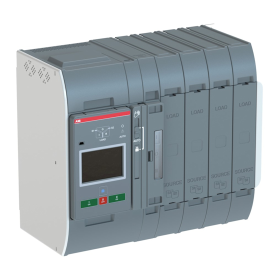
3 4 O X _ 3 0 - 1 6 0 0 r e v. B / 1 S C C 3 0 3 0 1 1 M 0 2 0 1 — 2. Product overview — Automatic transfer switches TruONE® ATS (type OX_), from 30 A up to 1600 A, are designed for use in emergency or standby systems to transfer a load automatically from one source to another. -
Page 14: General Overview
Tr u O N E ® AT S , I N S TA L L AT I O N A N D O P E R AT I N G I N S T R U C T I O N —... -
Page 15: Operation Types And Suitability Of Ekip-Modules
3 4 O X _ 3 0 - 1 6 0 0 r e v. B / 1 S C C 3 0 3 0 1 1 M 0 2 0 1 2.1.1 Differences of level types / operation types and suitability of Ekip-modules In this table you can find the differences of the controller level types 2, 3 and 4 in the... - Page 16 Tr u O N E ® AT S , I N S TA L L AT I O N A N D O P E R AT I N G I N S T R U C T I O N Ekip-modules suitable Operation types, TruONE®...
-
Page 17: Automatic Operation
3 4 O X _ 3 0 - 1 6 0 0 r e v. B / 1 S C C 3 0 3 0 1 1 M 0 2 0 1 — 2.2 HMI HMI is the control interface (Human the HMI with LCD-screen and level 4 Machine Interface), available in three contains the HMI with touch screen. -
Page 18: Truone® Ats Feature Comparison
Tr u O N E ® AT S , I N S TA L L AT I O N A N D O P E R AT I N G I N S T R U C T I O N —... - Page 19 3 4 O X _ 3 0 - 1 6 0 0 r e v. B / 1 S C C 3 0 3 0 1 1 M 0 2 0 1 Feature comparison Level 2 controls (DIP) Level 3 controls (LCD) Level 4 controls (TOUCH) LOAD AUTO LOAD...
- Page 20 ABB Ability : EDCS) For applications Mains - Mains Mains - Generator Contact ABB for applications with smaller than 20 kVA gensets — Table 2.2 ATS feature comparison, main features - but not limited to - in the table above...
-
Page 21: Typical Applications
3 4 O X _ 3 0 - 1 6 0 0 r e v. B / 1 S C C 3 0 3 0 1 1 M 0 2 0 1 — 2.4 Typical applications TruONE® automatic transfer switches are Source 1 Source 2 used for transferring a load automatically... - Page 22 Tr u O N E ® AT S , I N S TA L L AT I O N A N D O P E R AT I N G I N S T R U C T I O N Phase A Phase A Neutral...
-
Page 23: Description Of Basic Functionality
3 4 O X _ 3 0 - 1 6 0 0 r e v. B / 1 S C C 3 0 3 0 1 1 M 0 2 0 1 — 2.5 Description of basic functionality 2.5.1 Switching sequence / Automatic 2.5.1.1 Source 1 Priority (Source 2 = Generator) Switching sequence summary:... - Page 24 Tr u O N E ® AT S , I N S TA L L AT I O N A N D O P E R AT I N G I N S T R U C T I O N Source 1 priority (Source 2 = generator) Switch position I Switch position O...
- Page 25 3 4 O X _ 3 0 - 1 6 0 0 r e v. B / 1 S C C 3 0 3 0 1 1 M 0 2 0 1 2.5.1.2 Source 2 Priority (No generator) Switching sequence summary: Retransfer sequence summary: •...
- Page 26 Tr u O N E ® AT S , I N S TA L L AT I O N A N D O P E R AT I N G I N S T R U C T I O N Source 2 priority (no generator) Switch position I Switch position O...
- Page 27 3 4 O X _ 3 0 - 1 6 0 0 r e v. B / 1 S C C 3 0 3 0 1 1 M 0 2 0 1 2.5.1.3 No source Priority (Generator and load shed usage disabled) Retransfer steps following anomaly in the Switching to available source: source functioning:...
- Page 28 Tr u O N E ® AT S , I N S TA L L AT I O N A N D O P E R AT I N G I N S T R U C T I O N No Source priority (generator and load shed usage disabled) Switch position I Switch position O...
-
Page 29: Automatic Configuration
3 4 O X _ 3 0 - 1 6 0 0 r e v. B / 1 S C C 3 0 3 0 1 1 M 0 2 0 1 2.5.2 Automatic configuration 2.5.4 Powering supply scenarios Automatic configuration sequence can be Device can be powered: initiated by an HMI command. -
Page 30: Operating
Tr u O N E ® AT S , I N S TA L L AT I O N A N D O P E R AT I N G I N S T R U C T I O N —... -
Page 31: Operating And Locking
3 4 O X _ 3 0 - 1 6 0 0 r e v. B / 1 S C C 3 0 3 0 1 1 M 0 2 0 1 — 3.2 Operating and locking The operation mode is selected by using the slide switch (Hand - Locking - AUTO) located on the front of the automatic transfer switch (ATS). -
Page 32: Manual Mode, Operating By The Handle
Tr u O N E ® AT S , I N S TA L L AT I O N A N D O P E R AT I N G I N S T R U C T I O N —... - Page 33 3 4 O X _ 3 0 - 1 6 0 0 r e v. B / 1 S C C 3 0 3 0 1 1 M 0 2 0 1 I-position OXB_B: I - O - II O-position OXB_T: II - O - I O-position II-position...
-
Page 34: Automatic Mode, Operating By Hmi
Tr u O N E ® AT S , I N S TA L L AT I O N A N D O P E R AT I N G I N S T R U C T I O N I-position II-position OXA_B: I - II... -
Page 35: Led Functionality In Hmi
3 4 O X _ 3 0 - 1 6 0 0 r e v. B / 1 S C C 3 0 3 0 1 1 M 0 2 0 1 — 3.5 LED functionality in HMI ΔU 20% / Δf 10% Generator O Position stop delay... - Page 36 Tr u O N E ® AT S , I N S TA L L AT I O N A N D O P E R AT I N G I N S T R U C T I O N Bypass Lamp Auto...
-
Page 37: Using Level 2 (Dip) Control Interface Hmi
3 4 O X _ 3 0 - 1 6 0 0 r e v. B / 1 S C C 3 0 3 0 1 1 M 0 2 0 1 — 3.6 Using Level 2 (DIP) control interface HMI 3.6.1 Keypad S1 Failure S1 Return... -
Page 38: Configuration By Dip-Switches
Tr u O N E ® AT S , I N S TA L L AT I O N A N D O P E R AT I N G I N S T R U C T I O N 3.6.2 Configuration by DIP-switches LOAD AUTO... - Page 39 3 4 O X _ 3 0 - 1 6 0 0 r e v. B / 1 S C C 3 0 3 0 1 1 M 0 2 0 1 Manual retransfer: On: Manual retransfer to priority source enabled (automatic retransfer disabled) Off: Manual retransfer to priority source disabled (automatic retransfer...
-
Page 40: Using Level 3 (Lcd) Control Interface Hmi
Tr u O N E ® AT S , I N S TA L L AT I O N A N D O P E R AT I N G I N S T R U C T I O N —... -
Page 41: Using Level 4 (Touch) Control Interface Hmi
3 4 O X _ 3 0 - 1 6 0 0 r e v. B / 1 S C C 3 0 3 0 1 1 M 0 2 0 1 — 3.8 Using Level 4 (touch) control interface HMI 3.8.1 Keypad Home Button: Opens up the root menu or brings user to the homepage... -
Page 42: Navigating Menu
Tr u O N E ® AT S , I N S TA L L AT I O N A N D O P E R AT I N G I N S T R U C T I O N —... - Page 43 3 4 O X _ 3 0 - 1 6 0 0 r e v. B / 1 S C C 3 0 3 0 1 1 M 0 2 0 1 Description of the icons Alarm List 11:06 Alarm List System Overview Invalid Date S1 Ok...
-
Page 44: Start Screens
Tr u O N E ® AT S , I N S TA L L AT I O N A N D O P E R AT I N G I N S T R U C T I O N 4.1.1 Start screens 11:06 11:06... -
Page 45: Enter Key, Main Menu
3 4 O X _ 3 0 - 1 6 0 0 r e v. B / 1 S C C 3 0 3 0 1 1 M 0 2 0 1 4.1.2 Enter key, main menu Main menu Information When you have changed the parameter, always go back in the menu by pressing Esc- key and when prompted confirm changes with... - Page 46 Tr u O N E ® AT S , I N S TA L L AT I O N A N D O P E R AT I N G I N S T R U C T I O N Parameters *Default System parameters...
- Page 47 3 4 O X _ 3 0 - 1 6 0 0 r e v. B / 1 S C C 3 0 3 0 1 1 M 0 2 0 1 Parameters (continued) *Default Device Parameters In-phase Monitor Enable Off* Synchronization 0*...60 s...
- Page 48 Tr u O N E ® AT S , I N S TA L L AT I O N A N D O P E R AT I N G I N S T R U C T I O N Parameters (continued) *Default Device Parameters (continued)
- Page 49 3 4 O X _ 3 0 - 1 6 0 0 r e v. B / 1 S C C 3 0 3 0 1 1 M 0 2 0 1 Parameters (continued) *Default Device Parameters (continued) Voltage & Frequency Setpoints Defines the voltage and frequency limits for source being acceptable.
- Page 50 Tr u O N E ® AT S , I N S TA L L AT I O N A N D O P E R AT I N G I N S T R U C T I O N Parameters (continued) *Default Device Parameters (continued)
- Page 51 3 4 O X _ 3 0 - 1 6 0 0 r e v. B / 1 S C C 3 0 3 0 1 1 M 0 2 0 1 Measurements Switch Diagnostics Total operations I-O-II switches: Total number of transfers I-O, O-II, II-O and O-I.
- Page 52 Tr u O N E ® AT S , I N S TA L L AT I O N A N D O P E R AT I N G I N S T R U C T I O N Settings *Default Standard I/O Settings...
- Page 53 3 4 O X _ 3 0 - 1 6 0 0 r e v. B / 1 S C C 3 0 3 0 1 1 M 0 2 0 1 Settings (continued) *Default Standard I/O Settings (continued) O 01 (continued) Function (continued) Pre-transfer Signal Signal is activated and transfer is delayed according...
- Page 54 Tr u O N E ® AT S , I N S TA L L AT I O N A N D O P E R AT I N G I N S T R U C T I O N Test *Default On-Load Test Settings...
-
Page 55: Esc Key
3 4 O X _ 3 0 - 1 6 0 0 r e v. B / 1 S C C 3 0 3 0 1 1 M 0 2 0 1 4.1.3 Esc key Alarm List Invalid Date Ethernet disconnected —... -
Page 56: Level 4 (Touch) Control Interface, Menu Tree
System Overview Not Ok S1 Connected to Load Load Current 393 A Confirm Override S1 Fail TruONE ATS — — Fig. 4.8 Fig. 4.10 The default password is 00001, enter the The small icons in System Overview password when prompted (see Fig. 4.1). -
Page 57: System Overview
S1 Connected to Load S1 Connected to Load Load Current Load Current 393 A 393 A TruONE ATS — — Fig. 4.11 Fig. 4.12 On the lower edge of the screen you can While viewing a specific page, it can be see the Alarms. -
Page 58: Start Menu
— Fig. 4.14 By touching on Start Menu upper left corner -image you can move to the Overviews -pages, where you will find Switch status and TruONE ATS Supply info views, see the table below — Fig. 4.13 4.2.1.1 Overviews... - Page 59 Measurements Main Menu Measures Settings Test About TruONE ATS TruONE ATS — Fig. 4.15 By touching on Start Menu lower left corner -image you can move to the Main Menu page of Operation, Parameters, Measurements, Settings, Test and About, see the table below for the selections...
- Page 60 Tr u O N E ® AT S , I N S TA L L AT I O N A N D O P E R AT I N G I N S T R U C T I O N Parameters *Default System parameters...
- Page 61 3 4 O X _ 3 0 - 1 6 0 0 r e v. B / 1 S C C 3 0 3 0 1 1 M 0 2 0 1 Parameters (continued) *Default Device Parameters In-phase Monitor Enable Off* Synchronization 0*...60 s...
- Page 62 Tr u O N E ® AT S , I N S TA L L AT I O N A N D O P E R AT I N G I N S T R U C T I O N Parameters (continued) *Default Device Parameters (continued)
- Page 63 3 4 O X _ 3 0 - 1 6 0 0 r e v. B / 1 S C C 3 0 3 0 1 1 M 0 2 0 1 Parameters (continued) *Default Device Parameters (continued) Voltage & Frequency Setpoints Defines the voltage and frequency limits for source being acceptable.
- Page 64 Tr u O N E ® AT S , I N S TA L L AT I O N A N D O P E R AT I N G I N S T R U C T I O N Parameters (continued) *Default Device Parameters (continued)
- Page 65 3 4 O X _ 3 0 - 1 6 0 0 r e v. B / 1 S C C 3 0 3 0 1 1 M 0 2 0 1 Parameters (continued) *Default Device Parameters (continued) Manual Retransfer Off* Automatic retransfer sequence enabled.
- Page 66 Tr u O N E ® AT S , I N S TA L L AT I O N A N D O P E R AT I N G I N S T R U C T I O N Measurements Switch Diagnostic Total operations...
- Page 67 3 4 O X _ 3 0 - 1 6 0 0 r e v. B / 1 S C C 3 0 3 0 1 1 M 0 2 0 1 Settings *Default Standard I/O settings I 01 / I 02 / I 03 Function No function Input disabled Emergency Stop*...
- Page 68 Tr u O N E ® AT S , I N S TA L L AT I O N A N D O P E R AT I N G I N S T R U C T I O N Settings (continued) *Default Standard I/O settings (continued)
- Page 69 3 4 O X _ 3 0 - 1 6 0 0 r e v. B / 1 S C C 3 0 3 0 1 1 M 0 2 0 1 Settings (continued) *Default View Ammeter Phase I Max* S1 Voltmeter Phase V Max* S2 Voltmeter Phase...
- Page 70 Tr u O N E ® AT S , I N S TA L L AT I O N A N D O P E R AT I N G I N S T R U C T I O N Test *Default On-Load Test Settings...
- Page 71 4.2.1.3 Analog meters Overviews Analog Meters 0.0V Main Menu Measures TruONE ATS TruONE ATS — Fig. 4.16 By touching on Start Menu upper right corner -image you can find the analog meters information, see the table below S1 Voltage meter...
- Page 72 11:06 Overviews Analog Meters Voltages (S1) Main Menu Measures U0 0.0 TruONE ATS TruONE ATS — Fig. 4.17 By touching on Start Menu lower right corner -image you can find the measured data, see the table below Voltages (S1) Voltages (S2)
-
Page 73: Electronic Accessories
3 4 O X _ 3 0 - 1 6 0 0 r e v. B / 1 S C C 3 0 3 0 1 1 M 0 2 0 1 — 5. Electronic accessories Ekip Connect Sofware and Bluetooth and Ekip-modules mounted with auxiliary Programming -modules are suitable for all power supply module are (see chapters... -
Page 74: Using Ekip Connect -Software
Download it • Configure automatic transfer switches from the site, see the address below: with customized parameters. http://www.abb.com/abblibrary/ • Configure electronic accessories, con- DownloadCenter/ nected to automatic transfer switch via Local Bus. • Download information from automatic transfer switches. -
Page 75: Using Ekip Bluetooth-Module
3 4 O X _ 3 0 - 1 6 0 0 r e v. B / 1 S C C 3 0 3 0 1 1 M 0 2 0 1 — 5.2 Using Ekip Bluetooth-module The Ekip Bluetooth allows connection via It draws its power from a rechargeable Bluetooth between the automatic trans- lithium-polymer battery supplied with the... -
Page 76: Using Ekip Programming -Module
Tr u O N E ® AT S , I N S TA L L AT I O N A N D O P E R AT I N G I N S T R U C T I O N —... -
Page 77: Auxiliary Power Supply Module
3 4 O X _ 3 0 - 1 6 0 0 r e v. B / 1 S C C 3 0 3 0 1 1 M 0 2 0 1 — 5.4 Auxiliary power supply module The auxiliary power supply module, type control unit, for example: Operation of OXEA1, supplies non-insulated power to Sensor module isn't possible. -
Page 78: Using Ekip Signalling 2K
Tr u O N E ® AT S , I N S TA L L AT I O N A N D O P E R AT I N G I N S T R U C T I O N —... - Page 79 3 4 O X _ 3 0 - 1 6 0 0 r e v. B / 1 S C C 3 0 3 0 1 1 M 0 2 0 1 Settings (*Default) Description Modules (Optional modules) Ekip Signalling 2K-1 / -2 / -3 I 11/12, I 21/22, I 31/32 Function No Function*...
- Page 80 Tr u O N E ® AT S , I N S TA L L AT I O N A N D O P E R AT I N G I N S T R U C T I O N Settings (*Default) (continued) Description Modules (Optional modules) (continued)
- Page 81 3 4 O X _ 3 0 - 1 6 0 0 r e v. B / 1 S C C 3 0 3 0 1 1 M 0 2 0 1 5.5.3 Signals and inputs/outputs of Green LED for signalling the physical Ekip Signalling 2K-_ -module state of the input H x2 .
-
Page 82: Ekip Com Modbus Rtu -Module
Tr u O N E ® AT S , I N S TA L L AT I O N A N D O P E R AT I N G I N S T R U C T I O N —... - Page 83 3 4 O X _ 3 0 - 1 6 0 0 r e v. B / 1 S C C 3 0 3 0 1 1 M 0 2 0 1 5.6.1.1 Signallings 5.6.1.2 Termination resistor The following table illustrates the possi- On the Ekip Com Modbus RTU module it is ble signals, and their meaning: possible to activate the terminating resis-...
- Page 84 Tr u O N E ® AT S , I N S TA L L AT I O N A N D O P E R AT I N G I N S T R U C T I O N 5.6.1.3 Access from the display / Ekip Com Modbus RTU –module With modules energized the presence of...
-
Page 85: Ekip Com Profibus Dp -Module
3 4 O X _ 3 0 - 1 6 0 0 r e v. B / 1 S C C 3 0 3 0 1 1 M 0 2 0 1 5.6.2 Ekip Com Profibus DP -module It can be connected to a network RS-485 The Ekip Com Profibus DP is a communi- with protocol of Profibus communication, cation accessory module, that integrates... - Page 86 Tr u O N E ® AT S , I N S TA L L AT I O N A N D O P E R AT I N G I N S T R U C T I O N 5.6.2.1 Signallings The following table illustrates the possi- ble signals, and their meaning:...
- Page 87 3 4 O X _ 3 0 - 1 6 0 0 r e v. B / 1 S C C 3 0 3 0 1 1 M 0 2 0 1 5.6.2.2 Termination resistor The Ekip Com Profibus DP modules pro- vide the possibility to insert a 220 Ω...
- Page 88 Tr u O N E ® AT S , I N S TA L L AT I O N A N D O P E R AT I N G I N S T R U C T I O N 5.6.2.3 Access from the display / Ekip Com Profibus DP -module With modules energized the presence of...
-
Page 89: Ekip Com Devicenet -Module
3 4 O X _ 3 0 - 1 6 0 0 r e v. B / 1 S C C 3 0 3 0 1 1 M 0 2 0 1 5.6.3 Ekip Com DeviceNet -module It can be connected to a CAN network The Ekip Com DeviceNet –module is a with a DeviceNetTM communication pro- communication accessory module, that... - Page 90 Tr u O N E ® AT S , I N S TA L L AT I O N A N D O P E R AT I N G I N S T R U C T I O N 5.6.3.1 Signallings The following table illustrates the possi- ble signals, and their meaning:...
- Page 91 3 4 O X _ 3 0 - 1 6 0 0 r e v. B / 1 S C C 3 0 3 0 1 1 M 0 2 0 1 5.6.3.2 Termination resistor The modules provide the possibility to in- Information The termination resistors must never be in- sert a 120 Ω...
- Page 92 Tr u O N E ® AT S , I N S TA L L AT I O N A N D O P E R AT I N G I N S T R U C T I O N 5.6.3.3 Access from the display / Ekip Com DeviceNet –module With modules energized the presence of...
-
Page 93: Ekip Com Modbus Tcp -Module
3 4 O X _ 3 0 - 1 6 0 0 r e v. B / 1 S C C 3 0 3 0 1 1 M 0 2 0 1 5.6.4 Ekip Com Modbus TCP -module As an HTTP Server, connected to an Ether- Ekip Com Modbus TCP is an accessory net network it allows read-only access to module that can function as a communi-... - Page 94 Tr u O N E ® AT S , I N S TA L L AT I O N A N D O P E R AT I N G I N S T R U C T I O N The following table illustrates the ports used by the module: Port...
- Page 95 3 4 O X _ 3 0 - 1 6 0 0 r e v. B / 1 S C C 3 0 3 0 1 1 M 0 2 0 1 5.6.4.2 Access from the display / Ekip Com Modbus TCP –module With modules energized the presence of the modules on the module slot activates additional menus on the display:...
- Page 96 There are three IP Addresses of the client devices connected to the modules. MAC Address It is the address assigned by ABB, having a OUI equal to ac:d3:64 Organizationally Unique Identifier, formed from the first three bytes of a MAC address, and which uniquely identifies the manufacturer of an Ethernet device.
-
Page 97: Ekip Com Profinet -Module
3 4 O X _ 3 0 - 1 6 0 0 r e v. B / 1 S C C 3 0 3 0 1 1 M 0 2 0 1 5.6.5 Ekip Com Profinet -module The Ekip Com Profinet is a communica- Information The module can only be connected to net- tion accessory module, that integrates... - Page 98 Tr u O N E ® AT S , I N S TA L L AT I O N A N D O P E R AT I N G I N S T R U C T I O N The following table illustrates the ports used by the module: Ethertype...
- Page 99 Version Software version MAC Address It is the address assigned by ABB and with an OUI (Organizationally Unique Identifier, formed of the first three bytes of a MAC address, and which uniquely identifies the manufacturer of an Ethernet device) equal to ac:d3:64.
-
Page 100: Ekip Com Ethernet/Ip -Module
Tr u O N E ® AT S , I N S TA L L AT I O N A N D O P E R AT I N G I N S T R U C T I O N 5.6.6 Ekip Com EtherNet/IP -module The Ekip Com EtherNet/IP is an accessory Information... - Page 101 3 4 O X _ 3 0 - 1 6 0 0 r e v. B / 1 S C C 3 0 3 0 1 1 M 0 2 0 1 5.6.6.1 Signallings The following table illustrates the possi- ble signals, and their meaning: Indication Description...
- Page 102 Tr u O N E ® AT S , I N S TA L L AT I O N A N D O P E R AT I N G I N S T R U C T I O N 5.6.6.2 Access from the display / Ekip Com EtherNet/IP With modules energized the presence of...
- Page 103 There are three IP Addresses of the client devices connected to the modules. MAC Address It is the address assigned by ABB, having a OUI equal to ac:d3:64 Organizationally Unique Identifier, formed from the first three bytes of a MAC address, and which uniquely identifies the manufacturer of an Ethernet device.
-
Page 104: Ekip Com Iec 61850 -Module
Tr u O N E ® AT S , I N S TA L L AT I O N A N D O P E R AT I N G I N S T R U C T I O N 5.6.7 Ekip Com IEC 61850 -module The Ekip Com IEC 61850 is an accessory Information... - Page 105 3 4 O X _ 3 0 - 1 6 0 0 r e v. B / 1 S C C 3 0 3 0 1 1 M 0 2 0 1 The following table illustrates the ports used by the module: Ethertype Port Protocol...
- Page 106 Tr u O N E ® AT S , I N S TA L L AT I O N A N D O P E R AT I N G I N S T R U C T I O N 5.6.7.2 Access from the display / Ekip Com IEC 61850 With modules energized the presence of...
- Page 107 There are three IP Addresses of the client devices connected to the modules. MAC Address It is the address assigned by ABB, having a OUI equal to ac:d3:64 Organizationally Unique Identifier, formed from the first three bytes of a MAC address, and which uniquely identifies the manufacturer of an Ethernet device.
-
Page 108: Ekip Com Hub -Module
This dedicated cartridge-type thorized access, interference, intrusion, loss and/ or theft of data or information. ABB and communication module just needs to be its affiliates are not liable for damages and/... - Page 109 3 4 O X _ 3 0 - 1 6 0 0 r e v. B / 1 S C C 3 0 3 0 1 1 M 0 2 0 1 The following table illustrates the ports used by the module: Port Service Notes...
- Page 110 Tr u O N E ® AT S , I N S TA L L AT I O N A N D O P E R AT I N G I N S T R U C T I O N 5.6.8.2 Access from the display / Ekip Com Hub With modules energized the presence of...
- Page 111 IP address of the node to which the module is connected, in the presence of several subnets. MAC Address Address assigned by ABB, with OUI (Organizationally Unique Identifier) equal to ac:d3:64, which uniquely identifies the manufacturer of an Ethernet device.
-
Page 112: Troubleshooting
Tr u O N E ® AT S , I N S TA L L AT I O N A N D O P E R AT I N G I N S T R U C T I O N —... - Page 113 3 4 O X _ 3 0 - 1 6 0 0 r e v. B / 1 S C C 3 0 3 0 1 1 M 0 2 0 1 Message Fault Action S2 invalid frequency Frequency of source 2 is out of range Check the correlation between power set in parameters “Drop-out frequency, source and device configuration...
-
Page 114: Warnings
Tr u O N E ® AT S , I N S TA L L AT I O N A N D O P E R AT I N G I N S T R U C T I O N —... -
Page 115: Information
3 4 O X _ 3 0 - 1 6 0 0 r e v. B / 1 S C C 3 0 3 0 1 1 M 0 2 0 1 — 6.3 Information Touch Message Description Invalid Date Date not set Test on Load Test on load sequence active... -
Page 116: Technical Data
Tr u O N E ® AT S , I N S TA L L AT I O N A N D O P E R AT I N G I N S T R U C T I O N —... - Page 117 3 4 O X _ 3 0 - 1 6 0 0 r e v. B / 1 S C C 3 0 3 0 1 1 M 0 2 0 1 Automatic transfer switch, I/O contacts Cabling Rating / Remark Generator start/stop Cable size: 0.5…2.5 mm Stripping length;...
- Page 118 500 V [kA] OX_30...250_ Iq 100 kA rms. OFA_400 A gG 35.2 OFA_400 A aM 1030 Iq 50 kA rms. ABB T5L630_ 29.8 2084 OX_260...OX_400E_ Iq 100 kA rms. OFA_630 A gG 56.2 2790 OFA_630 A aM 56.8 3670 Iq 50 kA rms.
-
Page 119: Circuit Diagrams
RAW MATERIAL CREATED 2019-05-10 Jonna ECN NUMBER Fig. 7.2 Circuit diagram, OXA_B ORGANIZATION ABB Oy, Smart Po We reserve all rights in this document and in the information contained therein. Pidätämme itsellemme kaikki oikeudet tähän asiakirjaan ja siihen liittyvään informaatioon. - Page 120 Pidätämme itsellemme kaikki oikeudet tähän asiakirjaan ja siihen liittyvään informaatioon. Reproduction, use or disclosure to third parties without express authority is Asiakirjan toisintaminen, käyttö tai sen sisällön paljastaminen kolmannelle osapuolelle strictly forbidden. © Copyright 2019 ABB. ilman nimenomaista suostumustamme on ehdottomasti kielletty. © Copyright 2019 ABB.
- Page 121 ECN NUMBER Fig. 7.4 Circuit diagram, OXB_B ORGANIZATION ABB Oy, Smart Pow We reserve all rights in this document and in the information contained therein. Pidätämme itsellemme kaikki oikeudet tähän asiakirjaan ja siihen liittyvään informaatioon. Reproduction, use or disclosure to third parties without express authority is...
- Page 122 Tr u O N E ® AT S , I N S TA L L AT I O N A N D O P E R AT I N G I N S T R U C T I O N Ekip 2K-3 Ekip 2K-2 Ekip 2K-1...
- Page 123 3 4 O X _ 3 0 - 1 6 0 0 r e v. B / 1 S C C 3 0 3 0 1 1 M 0 2 0 1 — Installation instruction Automatic transfer switches Installation 8.1 Mounting the OX30...1600 automatic transfer switch 8.1.1 Drilling hole distances and labeling 8.1.2 Protection against direct contact...
- Page 124 Tr u O N E ® AT S , I N S TA L L AT I O N A N D O P E R AT I N G I N S T R U C T I O N Mounting of accessories 9.1 Terminal shrouds 9.2 Phase barriers...
- Page 125 3 4 O X _ 3 0 - 1 6 0 0 r e v. B / 1 S C C 3 0 3 0 1 1 M 0 2 0 1 — 8. Installation Before mounting the product, please, check the product identification from the product identification label, which is located on the front panel under the control interface unit (HMI).
- Page 126 Tr u O N E ® AT S , I N S TA L L AT I O N A N D O P E R AT I N G I N S T R U C T I O N —...
- Page 127 3 4 O X _ 3 0 - 1 6 0 0 r e v. B / 1 S C C 3 0 3 0 1 1 M 0 2 0 1 8.1.2 Protection against direct contact For protection against direct contact you can use the terminal shrouds when possi- ble or a plexiglass mounted over the product.
- Page 128 Tr u O N E ® AT S , I N S TA L L AT I O N A N D O P E R AT I N G I N S T R U C T I O N —...
- Page 129 3 4 O X _ 3 0 - 1 6 0 0 r e v. B / 1 S C C 3 0 3 0 1 1 M 0 2 0 1 8.2.2 Wiring of OX_800U…1600 / busbar connections and cable lugs Automatic Max.
- Page 130 Tr u O N E ® AT S , I N S TA L L AT I O N A N D O P E R AT I N G I N S T R U C T I O N OXEW1600_ —...
- Page 131 3 4 O X _ 3 0 - 1 6 0 0 r e v. B / 1 S C C 3 0 3 0 1 1 M 0 2 0 1 8.2.3 Lug assembly OZXA-100 OZXA-24 OZXA-800E OZXA-800L OZXA-200 OZXA-25 OZXA-30 OZXA-800S...
- Page 132 Tr u O N E ® AT S , I N S TA L L AT I O N A N D O P E R AT I N G I N S T R U C T I O N OZXA-24...26, OZXA-800L OZXA-100...400, OZXA-800E, OZXA-800S LOAD...
- Page 133 3 4 O X _ 3 0 - 1 6 0 0 r e v. B / 1 S C C 3 0 3 0 1 1 M 0 2 0 1 8.2.4 Phase barriers Phase barriers must be used between the LOAD side terminals of TruONE automatic transfers switches with switch types OX_400U/500E…1200U/1600E.
- Page 134 Tr u O N E ® AT S , I N S TA L L AT I O N A N D O P E R AT I N G I N S T R U C T I O N —...
- Page 135 3 4 O X _ 3 0 - 1 6 0 0 r e v. B / 1 S C C 3 0 3 0 1 1 M 0 2 0 1 8.4.2 Automatic mode; mounting of the 8.4.3 Mounting of the HMI handle to standby slot Automatic mode...
- Page 136 Tr u O N E ® AT S , I N S TA L L AT I O N A N D O P E R AT I N G I N S T R U C T I O N Max.
- Page 137 3 4 O X _ 3 0 - 1 6 0 0 r e v. B / 1 S C C 3 0 3 0 1 1 M 0 2 0 1 — 9. Mounting of accessories More information, see animation: Installation of accessories - TruONE®...
- Page 138 Tr u O N E ® AT S , I N S TA L L AT I O N A N D O P E R AT I N G I N S T R U C T I O N —...
- Page 139 3 4 O X _ 3 0 - 1 6 0 0 r e v. B / 1 S C C 3 0 3 0 1 1 M 0 2 0 1 — 9.3 Auxiliary contact blocks Position OA1G10 OA3G01 SOURCE 1 (S1), max 2+2 SOURCE 2 (S2), max 2+2 OA1G10...
- Page 140 Tr u O N E ® AT S , I N S TA L L AT I O N A N D O P E R AT I N G I N S T R U C T I O N —...
- Page 141 3 4 O X _ 3 0 - 1 6 0 0 r e v. B / 1 S C C 3 0 3 0 1 1 M 0 2 0 1 — 9.5 Auxiliary power supply and Ekip -modules Automatic transfer switches OX_ can be Max.
- Page 142 Tr u O N E ® AT S , I N S TA L L AT I O N A N D O P E R AT I N G I N S T R U C T I O N OXEA1 Ekip —...
- Page 143 3 4 O X _ 3 0 - 1 6 0 0 r e v. B / 1 S C C 3 0 3 0 1 1 M 0 2 0 1 — 9.6 HMI protective cover — HMI protective cover is available as acces- Fig.
- Page 144 Tr u O N E ® AT S , I N S TA L L AT I O N A N D O P E R AT I N G I N S T R U C T I O N 55.7 / 2.19 55.7 / 2.19 mm / in...
- Page 145 3 4 O X _ 3 0 - 1 6 0 0 r e v. B / 1 S C C 3 0 3 0 1 1 M 0 2 0 1 — 9.7 Terminal busbar Terminal busbar, type OXEW1600_, is needed for automatic transfer switches OX_800U...3200A on LOAD side terminals, when wiring is done with cable lugs.
-
Page 146: Dimension Drawings
Tr u O N E ® AT S , I N S TA L L AT I O N A N D O P E R AT I N G I N S T R U C T I O N —... - Page 147 3 4 O X _ 3 0 - 1 6 0 0 r e v. B / 1 S C C 3 0 3 0 1 1 M 0 2 0 1 5.16 6.65 7.20 0.16 3.19 0.98 228,5 11.81 242,5 12.01 18.94...
- Page 148 Tr u O N E ® AT S , I N S TA L L AT I O N A N D O P E R AT I N G I N S T R U C T I O N 6.65 7.20 0.16...
- Page 149 3 4 O X _ 3 0 - 1 6 0 0 r e v. B / 1 S C C 3 0 3 0 1 1 M 0 2 0 1 6.65 8.35 0.31 4.25 0.98 228,5 11.81 12.32 242,5 18.94 9.55...
- Page 150 Tr u O N E ® AT S , I N S TA L L AT I O N A N D O P E R AT I N G I N S T R U C T I O N 8.35 2.28 0.32...
- Page 151 — Notes...
- Page 152 — Notes...
- Page 153 — Notes...
- Page 154 — Notes...
- Page 155 — Notes...
- Page 156 — Notes...
- Page 157 — Notes...
- Page 158 With regard to purchase orders, the agreed particulars shall prevail. ABB does not accept any responsibility whatsoever for potential errors or possible lack of infor- mation in this document.
- Page 160 — Contact us ABB Oy P.O. Box 622 FI-65101 Vaasa Finland abb.com/lowvoltage www.abb.com/truone © Copyright 2019 ABB. All rights reserved. Specifications subject to change without notice.