
Related Manuals for ABB ZX1.5-R


Summary of Contents for ABB ZX1.5-R
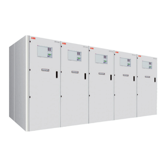
- Page 1 — I N S T R U C T I O N M A N U E L ZX1.5-R Gas-insulated medium voltage for railway application • Safety and reliability • 20% footprint saving • Easy operation • Complete solution...
-
Page 3: Table Of Contents
— Contents 1. Summary 2. Technical data 3. Design and function of the switchgear system and its equipment 4. Despatch and storage 5. Erection of the switchgear at site 6. Commissioning/operation 7. Maintenance/disposal 8. Table of equipment designations used... - Page 4 IEC 6227-200 when • the covers on the cable termination For any requests, please contact the ABB Assistance Service. compartment are not properly fitted, or Fundamental notes on this manual: Read the relevant sections of this manual through •...
-
Page 5: Summary
1.2.1 Switchgear production standards and • Climate specifications In areas with high humidity or major rapid The ZX1.5-R product comply with the following temperature changes, condensation inside standards: the low voltage compartment needs to be • Add GB/T 28428 prevented (e.g. - Page 6 Z X 1 . 5 - R I N S T R U C T I O N M A N U E L — 2 Technical data 2.1 Panel type ZX1.5-R Electrical Data Rated voltage 27.5/2x27.5 Rated power frequency withstand voltage...
-
Page 7: Technical Data
T E C H N I C A L D A T A 2.2 Busbar compartment with disconnector/earthing switch (three-position switch) type UX2TE-R Electrical data Rated voltage 27.5/2x27.5 Rated power frequency withstand line to earth voltage line to line Across the isolating distance Rated lightning impulse withstand line to earth voltage... - Page 8 2.3 Dimensions and weights — Figure 2/1: Dimensions View X View Y ZX1.5-R ZX1.5-R a) Feeder panel: up to 2 cable per line, rated current ≤ 1250 A A Circuit breaker compartment b) Feed panel with Busbar metring PT or SA: B Busbar compartment I cable per line, rated current ≤...
- Page 9 T E C H N I C A L D A T A Panel weights • When plasma diverters are used (standard), 800-1250 A versions : from approx. 550 kg up to thearc gases are conducted to the rear approx. 1000 kg Panel by panel for the circuit-breaker ...2500 A versions : up to 1650 kg compartment, and...
-
Page 10: Design And Function Of The Switchgear System And Its Equipment
Optionally, in systems with pressure relief The core modules of the metal-clad panels of type to the rear, discharge is effected centrally ZX1.5-R with separately gas-filled circuit breaker via the pressure relief duct (3.6) into a and busbar compartments are manufactured in a sectionalizer panel/busbar riser panel or laser cutting and auto robot welding process. - Page 11 • Details on the gas system and gas servicing 3.4 Disconnector/earthing switch, type UX2TE-R of the ZX1.5-R switchgear can be found in (Three-position switch) (Figures 3/7, 6/2, instruction manual HB605/10 Use of SF 6/4) insulating gas in ZX Switchgear Insulating The ZX1.5-R panels are fitted with specially...
- Page 12 If the circuit breaker is open, this flap can be opened and a hand crank (6.1) inserted for The following sensors are used in ZX1.5-R panels: operation of the disconnector or earthing switch. • Sensors for insulating gas pressure monitoring •...
- Page 13 D E S I G N A N D F U N C T I O N O F T H E S W I T C H G E A R S Y S T E M A N D I T S E Q U I P M E N T 3.8 Protection against maloperation / interlock Note dependencies (Figures 6/2, 6/5 and 7/1)
- Page 14 Z X 1 . 5 - R I N S T R U C T I O N M A N U E L 3.9.2 Manual earthing 3.10.1 Electrical earthing of a busbar section Follow the same sequence as for electrical using the sectionalizer/riser operation, but using the manual push buttons Operating sequence:...
- Page 15 (optional), with pressure relief duct at top (optional) — Figure 3/2 Panel type ZX1.5-R, rear view. Connection of two cables per line — — Figure 3/1 Figure 3/2...
- Page 16 Z X 1 . 5 - R I N S T R U C T I O N M A N U E L — Figure 3/3 Panel front view. Shown without low voltage compartment door — Figure 3/4 Panel top, pressure relief disk on the circuit breaker compartment Shown...
- Page 17 D E S I G N A N D F U N C T I O N O F T H E S W I T C H G E A R S Y S T E M A N D I T S E Q U I P M E N T —...
- Page 18 Insulating gas Circuit breaker Tee-off disconnector Tee-off earthing switch Current transformer Capacitive voltage divider Capacitive voltage divider, optional — Figure 3/7 2.34 ZX1.5-R 1.12 Insulating gas Circuit breaker 2.10 Tee-off disconnector Tee-off earthing switch Current transformer 3.15 2.11 Capacitive voltage divider...
- Page 19 D E S I G N A N D F U N C T I O N O F T H E S W I T C H G E A R S Y S T E M A N D I T S E Q U I P M E N T — Figure 3/9: Outgoing feeder panel (double pole) 2000 A, with 4 cables per pole and voltage transformer. ZX1.5-R Isolating system 2.9 is only to be operated when the feeder is off-circuit. Alwaysperform switching operations up to the limit positions and lock the isolating system.
- Page 20 I N S T R U C T I O N M A N U E L — Figure 3/11: Outgoing feeder panel (double pole) 2500 A, with 4 ZX1.5-R cables per pole and busbar voltage transformer, shown with pressure relief duct .
- Page 21 D E S I G N A N D F U N C T I O N O F T H E S W I T C H G E A R S Y S T E M A N D I T S E Q U I P M E N T —...
-
Page 22: Despatch And Storage
Z X 1 . 5 - R I N S T R U C T I O N M A N U E L — 4 Despatch and storage 4.1 Condition on delivery Always handle the panel in the upright The factory-assembled panels are checked for position. - Page 23 No other injurious environmental influences longer ensured • Store the panels upright Take action for further intermediate storage — Figure 4/1: Preparation for handling by crane. 1.19 Handling bracket (1.18) to be > 60∗ removed after handling ZX1.5-R 1.23 1.18 — Figure 4/1...
-
Page 24: Erection Of The Switchgear At Site
Z X 1 . 5 - R I N S T R U C T I O N M A N U E L — 5 Erection of the switchgear at site In the interests of the best possible erection •... - Page 25 (see also section 5.2.2) The relevant data for the order in hand can be Note Only prepare insulating parts and found in the ABB documentation. contact tubes for the panel currently The single or multiple panel foundation frame being erected. Protect them from can be supplied with the switchgear.
- Page 26 Z X 1 . 5 - R I N S T R U C T I O N M A N U E L — • Then join the two panels together by tightening • Check the bolted connection between main Figure 5/1a: Switchgear bolts (2.16) crosswise step by step...
- Page 27 E R E C T I O N O F T H E S W I T C H G E A R A T S I T E — Figure 5/1: Switchgear assembly — Figure 5/2a: Switchgear assembly, see figures 5/1 to 5/4 for details.
- Page 28 Z X 1 . 5 - R I N S T R U C T I O N M A N U E L — 2.18 Figure 5/3: Switchgear assembly 2.19 Earthing bar connection. — Figure 5/4: Switchgear assembly Panel/panel 2.20 connection.
- Page 29 E R E C T I O N O F T H E S W I T C H G E A R A T S I T E — Figure 5/7: Contact pin, silicone part and flange of the voltage transformer —...
- Page 30 Z X 1 . 5 - R I N S T R U C T I O N M A N U E L — Figure 5/11: Voltage transformer set for outgoing feeder panel and metering panel, panel width 800 mm —...
- Page 31 E R E C T I O N O F T H E S W I T C H G E A R A T S I T E Rear Channel Steel Front Layout of foundation frame — Figure5/16a Tolerance conditions for laying of the frame as follows: - Evenness tolerance: ±1 mm per meter - Straightness tolerance:max.
- Page 32 Z X 1 . 5 - R I N S T R U C T I O N M A N U E L 5.5 Installation of the pressure relief ducts Connect the wiring for the secondary The pressure relief ducts and the end covers connections and the earthing of the are to be installed in accordance with the voltage transformer in accordance with...
- Page 33 E R E C T I O N O F T H E S W I T C H G E A R A T S I T E 5.8 Final erection work • Clean the external surfaces of the enclosure and control cabinets in the switchgear where necessary and check for any damage to the paintwork, touching up with a suitable paint if...
-
Page 34: Commissioning/Operation
SF also apply accordingly to nitrogen (N2) performed with the control cabinet door closed • Display the ABB instruction manual on the handling of insulating gas and behaviour Opening the control cabinet door during faults in the switchroom constitutes intervention in the interlock system. - Page 35 C O M M I S S I O N I N G / O P E R A T I O N Key to the charging condition displays: • Switch the three-position switch on or off manually This requires the following actions: - Open the control cabinet door Discharged Charged...
- Page 36 With conventional panel control, the voltage indication system. details in the order documents are to be observed. Test procedure: Details on the gas system of the ZX1.5-R switchgear • Only use line comparators which comply with can be found in instruction manual.
- Page 37 C O M M I S S I O N I N G / O P E R A T I O N design of the display system in the relevant • Short-circuit the measuring sockets (1.6) switchgear or (4.5) in the panels concerned for the duration of the testing process at test •...
- Page 38 Z X 1 . 5 - R I N S T R U C T I O N M A N U E L 6.4.5 Maintenance earthing The wiring and in particular the earthing of the • Earthing of the busbar with the bus tie/riser, secondary terminals is to be implemented in as described in section 3.10 accordance with the circuit diagrams!
- Page 39 C O M M I S S I O N I N G / O P E R A T I O N — Figure 6/1: Handling of the door-lock — Figure6/2a: Operating mechanism of three position switch UX2TE-R with sensor control —...
- Page 40 Z X 1 . 5 - R I N S T R U C T I O N M A N U E L — Figure 6/4: Emergency manual operation, three position switch UX2TE-R — Figure 6/5: Cancellation of the interlock on the mechanical ON pushbutton for the circuit breaker...
-
Page 41: Maintenance/Disposal
Standards and specifications in the country immediately where the switch gear is erected Cleaning of external surfaces It is recommended that ABB after sales service • Remove dry, poorly adhering dust deposits with personnel be called in to perform servicing and a soft, dry cloth repair work. - Page 42 Z X 1 . 5 - R I N S T R U C T I O N M A N U E L • Sealed pressure system according to IEC 62271-1 • If correction is necessary,tie wire (2.35) is to be adjusted: gas contained in this system shall be recycled Release clamping screw (1.30) on clamping...
- Page 43 ) Delivery form: GCE0990253P0103 liquid gas in steel cylinders Observe the quality requirements to IEC 60376/VDE 0373 Observe the relevant ABB instruction manual BA GCEA901004P0102 1004/E, pp. 1 to 3, on safety at work! Note If extreme temperatures ≥50℃ Ccannot be...
-
Page 44: Table Of Equipment Designations Used
Z X 1 . 5 - R I N S T R U C T I O N M A N U E L — 8 Table of equipment designations used (Comparison of VDE and IEC designations) The equipment designations listed may deviate if so requested by the customer. Designation to VDE Designation to IEC Circuit breaker... - Page 45 T A B L E O F E Q U I P M E N T D E S I G N A T I O N S U S E D ZX1.5-R Gas-insulated medium voltage switchgear Instruction manual BA468/04E...
- Page 46 Z X 1 . 5 - R I N S T R U C T I O N M A N U E L 3.15 Pressure relief flap, optional Foundation frame 3.16 Socket for fully insulated bar Longitudinal bracket, (this one for panel 3.17 Fully insulated bar width 600 mm)
- Page 47 • Saving documents locally, updating automatically • Receive your expected messages • Online customer service You can use ABB Connect on iOS, Android and Windows 10 device via accessing ABB Connect webpage https://new.abb.com/low-voltage/zh/service/abb-connect or scanning the QR code ABB Connect...
- Page 48 — ABB Xiamen Switchgear Co., Ltd. No.885, FangShanXiEr Road, Xiang'an District, Xiamen, Fujian, 361101 Tel: 0592 602 6033 Fax: 0592 603 0505 ABB China Customer Service Hot Line TEL: 800-820-9696 / 400-820-9696 mail: cn-ep-hotline@abb.com www.abb.com All rights reserved. Specifications subject to change without notice.