Mitsubishi Electric MELSEC iQ-R Series User Manual
For melsec iq-r series programmable controllers
Hide thumbs
Also See for MELSEC iQ-R Series:
- Programming manual (2110 pages) ,
- User manual (760 pages) ,
- Reference manual (498 pages)
Table of Contents
Advertisement
MELSEC iQ-R I/O Module User's Manual
-RX10
-RX10-TS
-RX28
-RX40C7
-RX40C7-TS
-RX41C4
-RX41C4-TS
-RX42C4
-RX40PC6H
-RX40NC6H
-RX41C6HS
-RX61C6HS
-RX70C4
-RX71C4
-RX72C4
-RY10R2
-RY10R2-TS
-RY18R2A
-RY20S6
-RY40NT5P
-RY40NT5P-TS
-RY41NT2P
-RY41NT2P-TS
-RY41NT2H
-RY42NT2P
-RY40PT5P
-RY40PT5P-TS
-RY41PT1P
-RY41PT1P-TS
-RY41PT2H
-RY42PT1P
-RH42C4NT2P
-RG60
Advertisement
Table of Contents

Related Manuals for Mitsubishi Electric MELSEC iQ-R Series


Summary of Contents for Mitsubishi Electric MELSEC iQ-R Series
- Page 1 MELSEC iQ-R I/O Module User's Manual -RX10 -RY10R2 -RX10-TS -RY10R2-TS -RX28 -RY18R2A -RX40C7 -RY20S6 -RX40C7-TS -RY40NT5P -RX41C4 -RY40NT5P-TS -RX41C4-TS -RY41NT2P -RX42C4 -RY41NT2P-TS -RX40PC6H -RY41NT2H -RX40NC6H -RY42NT2P -RX41C6HS -RY40PT5P -RX61C6HS -RY40PT5P-TS -RX70C4 -RY41PT1P -RX71C4 -RY41PT1P-TS -RX72C4 -RY41PT2H -RY42PT1P -RH42C4NT2P -RG60...
-
Page 3: Safety Precautions
SAFETY PRECAUTIONS (Read these precautions before using this product.) Before using this product, please read this manual and the relevant manuals carefully and pay full attention to safety to handle the product correctly. The precautions given in this manual are concerned with this product only. For the safety precautions of the programmable controller system, refer to the MELSEC iQ-R Module Configuration Manual. - Page 4 [Design Precautions] WARNING ● Configure safety circuits external to the programmable controller to ensure that the entire system operates safely even when a fault occurs in the external power supply or the programmable controller. Incorrect output or malfunction due to a communication failure may result in an accident. (1) Emergency stop circuits, protection circuits, and protective interlock circuits for conflicting operations (such as forward/reverse rotations or upper/lower limit positioning) must be configured external to the programmable controller.
- Page 5 [Design Precautions] WARNING ● Especially, when a remote programmable controller is controlled by an external device, immediate action cannot be taken if a problem occurs in the programmable controller due to a communication failure. To prevent this, configure an interlock circuit in the program, and determine corrective actions to be taken between the external device and CPU module in case of a communication failure.
- Page 6 [Installation Precautions] WARNING ● Shut off the external power supply (all phases) used in the system before mounting or removing the module. Failure to do so may result in electric shock or cause the module to fail or malfunction. [Installation Precautions] CAUTION ●...
- Page 7 [Wiring Precautions] CAUTION ● Individually ground the FG and LG terminals of the programmable controller with a ground resistance of 100 ohm or less. Failure to do so may result in electric shock or malfunction. ● Use applicable solderless terminals and tighten them within the specified torque range. If any spade solderless terminal is used, it may be disconnected when the terminal screw comes loose, resulting in failure.
- Page 8 [Startup and Maintenance Precautions] WARNING ● Do not touch any terminal while power is on. Doing so will cause electric shock or malfunction. ● Correctly connect the battery connector. Do not charge, disassemble, heat, short-circuit, solder, or throw the battery into the fire. Also, do not expose it to liquid or strong shock. Doing so will cause the battery to produce heat, explode, ignite, or leak, resulting in injury and fire.
- Page 9 [Startup and Maintenance Precautions] CAUTION ● When connecting an external device with a CPU module or intelligent function module to modify data of a running programmable controller, configure an interlock circuit in the program to ensure that the entire system will always operate safely. For other forms of control (such as program modification, parameter change, forced output, or operating status change) of a running programmable controller, read the relevant manuals carefully and ensure that the operation is safe before proceeding.
- Page 10 [Startup and Maintenance Precautions] CAUTION ● Before handling the module, touch a conducting object such as a grounded metal to discharge the static electricity from the human body. Failure to do so may cause the module to fail or malfunction. [Operating Precautions] CAUTION ●...
-
Page 11: Conditions Of Use For The Product
CONDITIONS OF USE FOR THE PRODUCT (1) Mitsubishi programmable controller ("the PRODUCT") shall be used in conditions; i) where any problem, fault or failure occurring in the PRODUCT, if any, shall not lead to any major or serious accident; ii) where the backup and fail-safe function are systematically or automatically provided outside of the PRODUCT for the case of any problem, fault or failure occurring in the PRODUCT. -
Page 12: Introduction
Before using this product, please read this manual and the relevant manuals carefully and develop familiarity with the functions and performance of the MELSEC iQ-R series programmable controller to handle the product correctly. Please make sure that the end users read this manual. -
Page 13: Table Of Contents
CONTENTS SAFETY PRECAUTIONS ..............1 CONDITIONS OF USE FOR THE PRODUCT . - Page 14 Converter module and interface module (FA goods) ..........135 Appendix 2 Compatibility of MELSEC iQ-R series I/O Modules with MELSEC Q/L Series I/O Modules ..136 Appendix 3 External Dimensions .
-
Page 15: Relevant Manuals
This manual does not include information on the module FB. For details on the module FB, refer to the Function Block Reference for the module used. e-Manual refers to the Mitsubishi Electric FA electronic book manuals that can be browsed using a dedicated tool. -
Page 16: Chapter 1 Product Lists
PRODUCT LISTS Product Lists Input modules Module name Input specifications Number Current Weight Model Reference consumption occupied I/O points AC input module Terminal block 16 points 110mA 0.18kg RX10 Page 21 RX10 AC 100 to 120VAC, 16 points input module Spring clamp terminal block 0.14kg RX10-TS... - Page 17 Output modules Module name Output specifications Number Current Weight Model Reference consumption occupied I/O points Contact output module Terminal block 16 points 450mA 0.22kg RY10R2 Page 52 RY10R2 240VAC/24VDC, 2A/point, 16 points contact output module Spring clamp terminal block 0.19kg RY10R2- Page 54 RY10R2-TS 240VAC/24VDC, 2A/point, 16 points...
- Page 18 I/O combined module Module name Input Output Number Current Weight Model Reference specifications specifications consumption occupied I/O points DC input/ • Input part: 40-pin connector 40-pin connector 32 points 220mA 0.13kg RH42C4NT2P Page 85 transistor Positive/ 24VDC, 32 points 12 to 24VDC, RH42C4NT2P output negative...
-
Page 19: Reading A Model Name
Reading a Model Name • For the input module R X 4 0 P C 6 H - T S • For the output module R Y 4 0 N T 5 P - T S • For the I/O combined module R H 4 2 C 4 N T 2 P Item Symbol... - Page 20 Item Symbol Specifications Input module Output module AC input DC input Contact output Transistor output Triac output Current 0.1A specifications 0.2A 0.5A 0.6A ...
-
Page 21: Chapter 2 Part Names
PART NAMES This section describes the part names of the I/O module. 18-point screw terminal block type 40-pin connector type Spring clamp terminal block type (10) (10) Name Description RUN LED Indicates the operating status. On: In operation Flashing (400ms cycles): Selected as a module for the online module change Off: 5V power supply interrupted or module replacement allowed in the process of the online module change I/O status indicator LED Indicates the I/O status. - Page 22 MEMO 2 PART NAMES...
-
Page 23: Chapter 3 Specifications
SPECIFICATIONS This chapter describes the performance specifications. Performance Specifications This section describes the performance specifications of the I/O modules. Input modules RX10 AC input module Item Specifications Appearance Number of input points 16 points Rated input voltage, frequency 100 to 120VAC (+10%/-15%), 50/60Hz (3Hz) Input voltage distortion ratio Within 5% Rated input current... - Page 24 ■Circuit configuration Internal circuit TB16 TB17 100 to 120VAC ■Terminal connection Connection diagram viewed from the front of the module 100 to 120VAC X00 to X0F are signal names. The number of 1 to 18 indicates a terminal number. The terminal number 18 is empty. 3 SPECIFICATIONS 3.1 Performance Specifications...
- Page 25 RX10-TS AC input module Item Specifications Appearance Number of input points 16 points Rated input voltage, frequency 100 to 120VAC (+10%/-15%), 50/60Hz (3Hz) Input voltage distortion ratio Within 5% Rated input current 8.2mA (100VAC, 60Hz), 6.8mA (100VAC, 50Hz) Inrush current 200mA maximum within 1ms ON voltage/ON current 80VAC or higher/5mA or higher (50Hz, 60Hz)
- Page 26 ■Circuit configuration Internal circuit 100 to 120VAC ■Terminal connection Connection diagram viewed from the front of the module 1 10 2 11 3 12 4 13 5 14 6 15 7 16 8 17 9 18 100 to 120VAC X00 to X0F are signal names. The number of 1 to 18 indicates a terminal number.
- Page 27 RX28 AC input module Item Specifications Appearance Number of input points 8 points Rated input voltage, frequency 100 to 240VAC (+10%/-15%), 50/60Hz (3Hz) Input voltage distortion ratio Within 5% Rated input current 16.4mA (200VAC, 60Hz) 13.7mA (200VAC, 50Hz) 8.2mA (100VAC, 60Hz) 6.8mA (100VAC, 50Hz) Inrush current 950mA maximum within 1ms...
- Page 28 ■Terminal connection Connection diagram viewed from the front of the module 100 to 240VAC X00 to X07 are signal names. The number of 1 to 18 indicates a terminal number. The terminal number 2, 4, 6, 8, 10, 12, 14, 16, and 18 are empty. 3 SPECIFICATIONS 3.1 Performance Specifications...
- Page 29 RX40C7 DC input module Item Specifications Appearance Number of input points 16 points Rated input voltage 24VDC (ripple ratio: within 5%) (allowable voltage range: 20.4 to 28.8VDC) Rated input current 7.0mA TYP. (at 24VDC) ON voltage/ON current 15V or higher/4mA or higher OFF voltage/OFF current 8V or lower/2mA or lower Input resistance...
- Page 30 ■Input response time Timing Setting value 0.1ms 0.2ms 0.4ms 0.6ms 10ms 20ms 70ms OFFON (MAX) 0.1ms 0.2ms 0.4ms 0.6ms 10ms 20ms 70ms ONOFF (MAX) 0.35ms 0.4ms 0.5ms 0.7ms 10ms 20ms 70ms *1 The default value of input response time is 10ms. 3 SPECIFICATIONS 3.1 Performance Specifications...
- Page 31 RX40C7-TS DC input module Item Specifications Appearance Number of input points 16 points Rated input voltage 24VDC (ripple ratio: within 5%) (allowable voltage range: 20.4 to 28.8VDC) Rated input current 7.0mA TYP. (at 24VDC) ON voltage/ON current 15V or higher/4mA or higher OFF voltage/OFF current 8V or lower/2mA or lower Input resistance...
- Page 32 ■Input response time Timing Setting value 0.1ms 0.2ms 0.4ms 0.6ms 10ms 20ms 70ms OFFON (MAX) 0.1ms 0.2ms 0.4ms 0.6ms 10ms 20ms 70ms ONOFF (MAX) 0.35ms 0.4ms 0.5ms 0.7ms 10ms 20ms 70ms *1 The default value of input response time is 10ms. 3 SPECIFICATIONS 3.1 Performance Specifications...
- Page 33 RX41C4 DC input module Item Specifications Appearance Number of input points 32 points Rated input voltage 24VDC (ripple ratio: within 5%) (allowable voltage range: 20.4 to 28.8VDC) Rated input current 4.0mA TYP. (at 24VDC) ON voltage/ON current 19V or higher/3mA or higher OFF voltage/OFF current 6V or lower/1.0mA or lower Input resistance...
- Page 34 ■Terminal connection Connection diagram viewed from the front of the module 24VDC 24VDC X00 to X1F are signal names. A01 to A20 and B01 to B20 indicate pin numbers. A01 to A04, B03, and B04 are empty. ■Input response time Timing Setting value 0.1ms...
- Page 35 RX41C4-TS DC input module Item Specifications Appearance Number of input points 32 points Rated input voltage 24VDC (ripple ratio: within 5%) (allowable voltage range: 20.4 to 28.8VDC) Rated input current 4.0mA TYP. (at 24VDC) ON voltage/ON current 19V or higher/3mA or higher OFF voltage/OFF current 6V or lower/1.0mA or lower Input resistance...
- Page 36 ■Terminal connection Connection diagram viewed from the front of the module 24VDC 24VDC X00 to X1F are signal names. The number of 1 to 34 indicates a terminal number. The terminal number 34 is empty. ■Input response time Timing Setting value 0.1ms 0.2ms 0.4ms...
- Page 37 RX42C4 DC input module Item Specifications Appearance Number of input points 64 points Rated input voltage 24VDC (ripple ratio: within 5%) (allowable voltage range: 20.4 to 28.8VDC) Rated input current 4.0mA TYP. (at 24VDC) ON voltage/ON current 19V or higher/3mA or higher OFF voltage/OFF current 6V or lower/1.0mA or lower Input resistance...
- Page 38 ■Terminal connection Connection diagram viewed from the front of the module 1B20 1A20 2B20 2A20 1B19 1A19 2B19 2A19 1B18 1A18 2B18 2A18 1B17 1A17 2B17 2A17 1B16 1A16 2B16 2A16 1B15 1A15 2B15 2A15 1B14 1A14 2B14 2A14 1B13 1A13 2B13 2A13...
- Page 39 RX70C4 DC input module Item Specifications Appearance Number of input points 16 points Rated input voltage 5VDC (ripple ratio: within 5%) 12VDC (ripple ratio: within 5%) (allowable voltage range: 4.25 to (allowable voltage range: 10.2 to 6VDC) 14.4VDC) Rated input current 1.7mA TYP.
- Page 40 ■Terminal connection Connection diagram viewed from the front of the module 5/12VDC 5/12VDC X00 to X0F are signal names. The number of 1 to 18 indicates a terminal number. The terminal number 18 is empty. ■Input response time Timing Setting value 0.1ms 0.2ms 0.4ms...
- Page 41 RX71C4 DC input module Item Specifications Appearance Number of input points 32 points Rated input voltage 5VDC (ripple ratio: within 5%) 12VDC (ripple ratio: within 5%) (allowable voltage range: 4.25 to (allowable voltage range: 10.2 to 6VDC) 14.4VDC) Rated input current 1.7mA TYP.
- Page 42 ■Terminal connection Connection diagram viewed from the front of the module 5/12VDC 5/12VDC X00 to X1F are signal names. A01 to A20 and B01 to B20 indicate pin numbers. A01 to A04, B03, and B04 are empty. ■Input response time Timing Setting value 0.1ms...
- Page 43 RX72C4 DC input module Item Specifications Appearance Number of input points 64 points Rated input voltage 5VDC (ripple ratio: within 5%) 12VDC (ripple ratio: within 5%) (allowable voltage range: 4.25 to (allowable voltage range: 10.2 to 6VDC) 14.4VDC) Rated input current 1.7mA TYP.
- Page 44 ■Terminal connection Connection diagram viewed from the front of the module 1B20 1A20 2B20 2A20 1B19 1A19 2B19 2A19 1B18 1A18 2B18 2A18 1B17 1A17 2B17 2A17 1B16 1A16 2B16 2A16 1B15 1A15 2B15 2A15 1B14 1A14 2B14 2A14 1B13 1A13 2B13 2A13...
- Page 45 RX40PC6H DC high-speed input module Item Specifications Appearance Number of input points 16 points Rated input voltage 24VDC (ripple ratio: within 5%) (allowable voltage range: 20.4 to 28.8VDC) Rated input current 6.0mA TYP. (at 24VDC) ON voltage/ON current 15V or higher/4mA or higher OFF voltage/OFF current 8V or lower/1.7mA or lower Input resistance...
- Page 46 ■Terminal connection Connection diagram viewed from the front of the module COM1+ 24VDC 24VDC COM2+ X00 to X0F are signal names. The number of 1 to 18 indicates a terminal number. ■Input response time Timing Setting value 20s 50s 0.1ms 0.2ms 0.4ms 0.6ms...
- Page 47 RX40NC6H DC high-speed input module Item Specifications Appearance Number of input points 16 points Rated input voltage 24VDC (ripple ratio: within 5%) (allowable voltage range: 20.4 to 28.8VDC) Rated input current 6.0mA TYP. (at 24VDC) ON voltage/ON current 15V or higher/4mA or higher OFF voltage/OFF current 8V or lower/1.7mA or lower Input resistance...
- Page 48 ■Terminal connection Connection diagram viewed from the front of the module COM1- 24VDC 24VDC COM2- X00 to X0F are signal names. The number of 1 to 18 indicates a terminal number. ■Input response time Timing Setting value 20s 50s 0.1ms 0.2ms 0.4ms 0.6ms...
- Page 49 RX41C6HS DC high-speed input module Item Specifications Appearance Number of input points 32 points Rated input voltage 24VDC (ripple ratio: within 5%) (allowable voltage range: 20.4 to 28.8VDC) Rated input current 6.0mA TYP. (at 24VDC) ON voltage/ON current 19V or higher/4mA or higher OFF voltage/OFF current 6V or lower/1.7mA or lower Input resistance...
- Page 50 ■Terminal connection Connection diagram viewed from the front of the module 24VDC 24VDC X00 to X1F are signal names. A01 to A20 and B01 to B20 indicate pin numbers. A01 to A04, B03, and B04 are empty. ■Input response time Timing Setting value 10s...
- Page 51 RX61C6HS DC high-speed input module Item Specifications Appearance Number of input points 32 points Rated input voltage 5VDC (ripple ratio: within 5%) (allowable voltage range: 4.25 to 6VDC) Rated input current 6.0mA TYP. (at 5VDC) ON voltage/ON current 3.5V or higher/3mA or higher OFF voltage/OFF current 1V or lower/1mA or lower Input resistance...
- Page 52 ■Terminal connection Connection diagram viewed from the front of the module 5VDC 5VDC X00 to X1F are signal names. A01 to A20 and B01 to B20 indicate pin numbers. A01 to A04, B03, and B04 are empty. ■Input response time Timing Setting value 10s...
-
Page 53: Output Modules
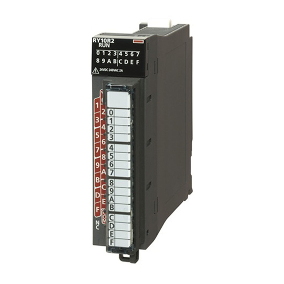
Output modules The following output modules are equipped with the overload protection function and overheat protection function. Applicable module modelsRY40NT5P, RY40NT5P-TS, RY41NT2P, RY41NT2P-TS, RY42NT2P, RY40PT5P, RY40PT5P- TS, RY41PT1P, RY41PT1P-TS, RY42PT1P Function Description Overload protection • If an output module detects an overcurrent, current limiter operation is activated to limit the output current. - Page 54 RY10R2 contact output module Item Specifications Appearance Number of output points 16 points Rated switching voltage/current 24VDC 2A (resistive load)/point, 8A/common 240VAC 2A (COS = 1)/point, 8A/common Minimum switching load 5VDC, 1mA Maximum switching load 264VAC 125VDC Response time OFFON 10ms or less ONOFF 12ms or less...
- Page 55 ■Terminal connection Connection diagram viewed from the front of the module Load Load Load Load Load Load Load Load Load Load Load Load Load Load Load Load External load power supply Y00 to Y0F are signal names. The number of 1 to 18 indicates a terminal number. The terminal number 18 is empty.
- Page 56 RY10R2-TS contact output module Item Specifications Appearance Number of output points 16 points Rated switching voltage/current 24VDC 2A (resistive load)/point, 8A/common 240VAC 2A (COS = 1)/point, 8A/common Minimum switching load 5VDC, 1mA Maximum switching load 264VAC 125VDC Response time OFFON 10ms or less ONOFF 12ms or less...
- Page 57 ■Terminal connection Connection diagram viewed from the front of the module Load Load 1 10 Load Load 2 11 Load Load 3 12 Load Load 4 13 Load Load 5 14 Load Load 6 15 Load Load 7 16 Load Load 8 17 External load...
- Page 58 RY18R2A contact output module (all points independent contact) Item Specifications Appearance Number of output points 8 points Rated switching voltage/current 24VDC 2A (resistive load)/point, 8A/module 240VAC 2A (COS = 1)/point, 8A/module Minimum switching load 5VDC, 1mA Maximum switching load 264VAC 125VDC Response time OFFON 10ms or less...
- Page 59 ■Terminal connection Connection diagram viewed from the front of the module Load External load power supply Load External load power supply Load External load power supply Load External load power supply Load External load power supply Load External load power supply Load External load power supply Load...
- Page 60 RY20S6 triac output module Item Specifications Appearance Number of output points 16 points Rated load voltage, frequency 100 to 240VAC (+10%/-15%), 50/60Hz (3Hz) Maximum load current 0.6A/point, 4.8A/common Load voltage distortion ratio Within 5% Maximum load voltage 264VAC Minimum load voltage/current 24VAC/100mA, 100VAC/25mA, 240VAC/25mA Maximum inrush current 20A/cycle or lower...
- Page 61 ■Terminal connection Connection diagram viewed from the front of the module Load Load Load Load Load Load Load Load Load Load Load Load Load Load Load Load 100 to 240VAC Y00 to Y0F are signal names. The number of 1 to 18 indicates a terminal number. The terminal number 18 is empty.
- Page 62 RY40NT5P transistor output module Item Specifications Appearance Number of output points 16 points Rated load voltage 12/24VDC (allowable voltage range: 10.2 to 28.8VDC) Maximum load current 0.5A/point, Pilot Duty, 5A/common Maximum inrush current Current is to be limited by the overload protection function. Leakage current at OFF 0.1mA or lower Maximum voltage drop at ON...
- Page 63 ■Terminal connection Connection diagram viewed from the front of the module Load Load Load Load Load Load Load Load Load Load Load Load Load Load Load Load +V (12/24VDC) 12/24VDC Y00 to Y0F are signal names. The number of 1 to 18 indicates a terminal number. 3 SPECIFICATIONS 3.1 Performance Specifications...
- Page 64 RY40NT5P-TS transistor output module Item Specifications Appearance Number of output points 16 points Rated load voltage 12/24VDC (allowable voltage range: 10.2 to 28.8VDC) Maximum load current 0.5A/point, Pilot Duty, 5A/common Maximum inrush current Current is to be limited by the overload protection function. Leakage current at OFF 0.1mA or lower Maximum voltage drop at ON...
- Page 65 ■Terminal connection Connection diagram viewed from the front of the module Load Load Load Load Load Load Load Load Load Load Load Load Load Load Load Load +V (12/24VDC) 12/24VDC Y00 to Y0F are signal names. The number of 1 to 18 indicates a terminal number. 3 SPECIFICATIONS 3.1 Performance Specifications...
- Page 66 RY41NT2P transistor output module Item Specifications Appearance Number of output points 32 points Rated load voltage 12/24VDC (allowable voltage range: 10.2 to 28.8VDC) Maximum load current 0.2A/point, Pilot Duty, 2A/common Maximum inrush current Current is to be limited by the overload protection function. Leakage current at OFF 0.1mA or lower Maximum voltage drop at ON...
- Page 67 ■Terminal connection Connection diagram viewed from the front of the module Load Load Load Load Load Load Load Load Load Load Load Load Load Load Load Load Load Load Load Load Load Load Load Load Load Load Load Load Load Load Load Load...
- Page 68 RY41NT2P-TS transistor output module Item Specifications Appearance Number of output points 32 points Rated load voltage 12/24VDC (allowable voltage range: 10.2 to 28.8VDC) Maximum load current 0.2A/point, Pilot Duty, 2A/common Maximum inrush current Current is to be limited by the overload protection function. Leakage current at OFF 0.1mA or lower Maximum voltage drop at ON...
- Page 69 ■Terminal connection Connection diagram viewed from the front of the module Load Load Load Load Load Load Load Load Load Load Load Load Load Load Load Load Load Load Load Load Load Load Load Load Load Load Load Load Load Load Load Load...
- Page 70 RY41NT2H transistor high-speed output module Item Specifications Appearance Number of output points 32 points Rated load voltage 5/12/24VDC (allowable voltage range: 4.25 to 28.8VDC) Maximum load current 0.2A/point, 2A/common Maximum inrush current 0.7A, 10ms or less Leakage current at OFF 0.1mA or lower Maximum voltage drop at ON 0.1VDC (TYP.) 0.2A, 0.2VDC (MAX.) 0.2A...
- Page 71 ■Terminal connection Connection diagram viewed from the front of the module Load Load Load Load Load Load Load Load Load Load Load Load Load Load Load Load Load Load Load Load Load Load Load Load Load Load Load Load Load Load Load Load...
- Page 72 RY42NT2P transistor output module Item Specifications Appearance Number of output points 64 points Rated load voltage 12/24VDC (allowable voltage range: 10.2 to 28.8VDC) Maximum load current 0.2A/point, Pilot Duty, 2A/common Maximum inrush current Current is to be limited by the overload protection function. Leakage current at OFF 0.1mA or lower Maximum voltage drop at ON...
- Page 73 ■Terminal connection Connection diagram viewed from the front of the module Load Load Load Load 1B20 1A20 2B20 2A20 Load Load Load Load 1B19 1A19 2B19 2A19 Load Load Load Load 1B18 1A18 2B18 2A18 Load Load Load Load 1B17 1A17 2B17 2A17...
- Page 74 RY40PT5P transistor output module Item Specifications Appearance Number of output points 16 points Rated load voltage 12/24VDC (allowable voltage range: 10.2 to 28.8VDC) Maximum load current 0.5A/point, Pilot Duty, 5A/common Maximum inrush current Current is to be limited by the overload protection function. Leakage current at OFF 0.1mA or lower Maximum voltage drop at ON...
- Page 75 ■Terminal connection Connection diagram viewed from the front of the module Load Load Load Load Load Load Load Load Load Load Load Load Load Load Load Load 12/24VDC Y00 to Y0F are signal names. The number of 1 to 18 indicates a terminal number. 3 SPECIFICATIONS 3.1 Performance Specifications...
- Page 76 RY40PT5P-TS transistor output module Item Specifications Appearance Number of output points 16 points Rated load voltage 12/24VDC (allowable voltage range: 10.2 to 28.8VDC) Maximum load current 0.5A/point, Pilot Duty, 5A/common Maximum inrush current Current is to be limited by the overload protection function. Leakage current at OFF 0.1mA or lower Maximum voltage drop at ON...
- Page 77 ■Terminal connection Connection diagram viewed from the front of the module Load Load Load Load Load Load Load Load Load Load Load Load Load Load Load Load 12/24VDC Y00 to Y0F are signal names. The number of 1 to 18 indicates a terminal number. 3 SPECIFICATIONS 3.1 Performance Specifications...
- Page 78 RY41PT1P transistor output module Item Specifications Appearance Number of output points 32 points Rated load voltage 12/24VDC (allowable voltage range: 10.2 to 28.8VDC) Maximum load current 0.1A/point, Pilot Duty, 2A/common Maximum inrush current Current is to be limited by the overload protection function. Leakage current at OFF 0.1mA or lower Maximum voltage drop at ON...
- Page 79 ■Terminal connection Connection diagram viewed from the front of the module Load Load Load Load Load Load Load Load Load Load Load Load Load Load Load Load Load Load Load Load Load Load Load Load Load Load Load Load Load Load Load Load...
- Page 80 RY41PT1P-TS transistor output module Item Specifications Appearance Number of output points 32 points Rated load voltage 12/24VDC (allowable voltage range: 10.2 to 28.8VDC) Maximum load current 0.1A/point, Pilot Duty, 2A/common Maximum inrush current Current is to be limited by the overload protection function. Leakage current at OFF 0.1mA or lower Maximum voltage drop at ON...
- Page 81 ■Terminal connection Connection diagram viewed from the front of the module Load Load Load Load Load Load Load Load Load Load Load Load Load Load Load Load Load Load Load Load Load Load Load Load Load Load Load Load Load Load Load Load...
- Page 82 RY41PT2H transistor high-speed output module Item Specifications Appearance Number of output points 32 points Rated load voltage 5/12/24VDC (allowable voltage range: 4.25 to 28.8VDC) Maximum load current 0.2A/point, 2A/common Maximum inrush current 0.7A, 10ms or less Leakage current at OFF 0.1mA or lower Maximum voltage drop at ON 0.1VDC (TYP.) 0.2A, 0.2VDC (MAX.) 0.2A...
- Page 83 ■Terminal connection Connection diagram viewed from the front of the module Load Load Load Load Load Load Load Load Load Load Load Load Load Load Load Load Load Load Load Load Load Load Load Load Load Load Load Load Load Load Load Load...
- Page 84 RY42PT1P transistor output module Item Specifications Appearance Number of output points 64 points Rated load voltage 12/24VDC (allowable voltage range: 10.2 to 28.8VDC) Maximum load current 0.1A/point, Pilot Duty, 2A/common Maximum inrush current Current is to be limited by the overload protection function. Leakage current at OFF 0.1mA or lower Maximum voltage drop at ON...
- Page 85 ■Terminal connection Connection diagram viewed from the front of the module Load Load Load Load 1A20 1B20 2B20 2A20 Load Load Load Load 1B19 1A19 2B19 2A19 Load Load Load Load 1B18 1A18 2B18 2A18 Load Load Load Load 1B17 1A17 2B17 2A17...
-
Page 86: I/O Combined Module
I/O combined module The I/O combined module is equipped with the overload protection function and overheat protection function. Function Description Overload protection • If the output side detects an overcurrent, current limiter operation is activated to limit the output current. •... - Page 87 RH42C4NT2P DC input/transistor output combined module Item Specifications Appearance Input specifications Number of input points 32 points Rated input voltage 24VDC (ripple ratio: within 5%) (allowable voltage range: 20.4 to 28.8VDC) Rated input current 4.0mA TYP. (at 24VDC) ON voltage/ON current 19V or higher/3mA or higher OFF voltage/OFF current 6V or lower/1.0mA or lower...
- Page 88 ■Circuit configuration 1B20 Internal circuit 1A05 Left side connectors (Input) Indication selector Right side connectors circuit 1B01,1B02 (Output) 24VDC Load 2B20 24VDC Internal circuit Load 2A05 Constant 2B01,2B02 voltage circuit 2A01,2A02 12/24VDC *1 The LED indicates the input (X00 to X1F) by turning the switch to the left (F), while the LED indicates the output (Y00 to Y1F) by turning the switch to the right (L).
-
Page 89: Blank Cover Module
Blank cover module RG60 blank cover module Item Specifications Appearance Number of occupied I/O points Default: 16 points (can be changed to 0, 16, 32, 48, 64, 128, 256, 512, or 1024 points in the I/O assignment setting of the system parameters) Application Used for dust prevention in the space where an I/O module is not mounted (especially the empty slot between modules). -
Page 90: Function List
Function List This section lists the functions of the I/O module. Item Description Reference Input response time setting Allows changing the input response times of input modules by each input point. The Page 115 Input Response Time input modules take in external input for the set input response time. Setting Interrupt input function Generates an interrupt from an input module. -
Page 91: Chapter 4 Procedures Before Operation
PROCEDURES BEFORE OPERATION This chapter describes the procedures before operation. Mounting a module Mount the I/O module in any desired configuration. Page 91 SYSTEM CONFIGURATION Wiring Perform wiring of external devices to the I/O module. Page 104 Wiring Adding a module Add the I/O module to a module configuration by using the engineering tool. - Page 92 MEMO 4 PROCEDURES BEFORE OPERATION...
-
Page 93: Chapter 5 System Configuration
SYSTEM CONFIGURATION This chapter describes the system configuration of the I/O module. System Configuration System configuration example when I/O modules are used The following figure shows an example of the system configuration when I/O modules are used. (1): Spring clamp terminal block (2): Dedicated cable with connector (relay terminal module) (optional) (3): Dedicated cable with connector (connector/terminal block converter module) (optional) (4) Connector... - Page 94 Recommended optional items To perform the module wiring easier, the following products are prepared as optional items. ■Connector/terminal block converter module and dedicated cable with connector Used for the easy wiring from a connector type I/O module to an external wiring terminal block. Page 129 Connector/terminal block converter modules ■Relay terminal module and dedicated cable with connector Used as a substitute for the relay terminal blocks and relays in a control panel, which reduces the man-hours for wiring among...
-
Page 95: Applicable Systems
Applicable Systems Compatible software version To ensure compatibility of the software version, always update GX Works3 to the latest version. 5 SYSTEM CONFIGURATION 5.2 Applicable Systems... -
Page 96: Chapter 6 Installation And Wiring
INSTALLATION AND WIRING This chapter describes the installation and wiring of the I/O modules. Before Using the I/O Modules Input modules Precautions common to all input modules ■Number of simultaneous ON points The number of input points that can be turned on at the same time varies depending on the input voltage and ambient temperature. -
Page 97: Output Modules
Output modules Precautions common to all output modules ■Maximum switching frequency when L load is driven The maximum switching frequency imposes a limit on the use; an ON state or an OFF state must not be changed without an interval of at least one second. ■Load to be connected When connecting a counter or timer utilizing a DC-DC converter as a load of the output module, select an output module whose maximum load current is higher than the inrush current of a load to be connected. - Page 98 ■Measures against back EMF When connecting an inductive load, connect a diode in parallel with the load. Use the diode that satisfies the following conditions: • A reverse breakdown voltage is more than ten times as high as the circuit voltage. •...
- Page 99 Precautions when using the contact output module When using the contact output module, carefully consider the following points: • Relay life (contact switching life) • Influence on the relay life by a connected load • Measures against back EMF ■Relay life (contact switching life) Applicable moduleRY10R2, RY10R2-TS, RY18R2A The relay life varies depending on the environment where a module is used.
- Page 100 ■Influence on the relay life by a connected load An actual relay life can be substantially shorter than the relay life curve depending on the type of a connected load and the characteristics of its inrush current. Page 97 Relay life (contact switching life) The inrush current generated by a connected load can lead to contact welding of the module.
- Page 101 Load type Waveform Inrush current Waveform Inrush current i/rated current i/rated current Capacitive load Capacitive load Approx. 20 to 40 times i: Inrush current io: Rated current t: 0.008 to 0.33 seconds (0.5 to 2 cycle) *1 A typical discharge lamp circuit is configured with a combination of discharge tubes, transformers, choke coils, capacitors and others. Because of this, be especially careful of the case of a high power factor and a low power supply impedance, where the inrush current flowing into the output module can be 20 to 40 times as high as the rated current.
- Page 102 ■Measures against back EMF Provide a contact protection circuit for an extended contact life, noise prevention at contact close, and reduction of the carbides and nitric acids formed by an arc discharge. An incorrect circuit involves a high risk of contact welding. With the contact protection circuit, the recovery time may be delayed.
- Page 103 Precautions when using the triac output module Because of characteristics of a triac, a sudden change of voltage or current may cause unstable operations of a triac used for the triac output module. Whether the voltage or current change causes a problem differs depending on an individual part (each triac), thus check the following when using the triac output module.
- Page 104 ■Measures for connecting an inductive load To connect an inductive load, take measures to reduce noise to the side where the load is connected as shown below. Circuit example Element selection criteria Remarks Varistor method Select a varistor whose cut-off voltage (Vc) The recovery time is a little delayed.
-
Page 105: I/O Combined Module
I/O combined module This section describes the precautions specific to the I/O combined module. The precautions other than the following are the same as the input module and output module. ( Page 94 Input modules, Page 95 Output modules) I/O numbers of the I/O combined module The I/O combined module assigns the same I/O number to each input and output. -
Page 106: Wiring
1.5 (22 to 16 AWG) can be used when a spring clamp terminal block (Q6TE-18SN) is used instead. To use a wire of larger size than the one described in the above table, take a measure by using FA goods of Mitsubishi Electric Engineering Co., Ltd. (such as FA- TB161AC+ FA-CBL20D). -
Page 107: 40-Pin Connector Type Module
40-pin connector type module Precautions • Use copper wire with a temperature rating of 75 or higher for the connector. • Tighten the connector screws within the following specified torque range. Screw Tightening torque range Connector screw (M2.6) 0.20 to 0.29Nm Applicable connectors 40-pin connectors to be used for an input module, output module, and I/O combined module are sold separately. -
Page 108: Spring Clamp Terminal Block (Lever Type)
Spring clamp terminal block (lever type) Precautions • Use bar solderless terminals for wiring to the terminal block. If a stripped wire is inserted into a wire insertion opening, the wire cannot be securely clamped. • For how long the wire should be stripped, follow the specifications of the bar solderless terminal used. To attach a bar solderless terminal to a wire, use a crimping tool. - Page 109 Processing method of the cable terminal Strip the cable from the tip to connect a bar solderless terminal at the stripped area. For how long the cable should be stripped, follow the specifications of the bar solderless terminal used. Stripping the cable too long may cause electric shock or short circuit between adjacent terminals because the conductive part sticks out of the terminal block.
-
Page 110: Input Wiring Examples
Input Wiring Examples The following figures show examples of wiring between the DC input module and connectable DC input devices (DC output type). Wiring example for contact output type The wiring example for the DC input module (1) and the contact output type (2) is shown below. Wiring example for DC 2-wire type The wiring example for the DC input module (1) and the DC 2-wire type (2) is shown below. - Page 111 Wiring example for voltage output type The wiring example for the DC input module (1) and the voltage output type (2) is shown below. Output Power supply for sensor When connecting to the voltage output type (1) sensor, avoid the wiring as shown below. In the wiring below, a current flows into the DC input module through the pull-up resistor (2) in the sensor.
-
Page 112: Chapter 7 Parameter Settings
PARAMETER SETTINGS This chapter describes the parameter settings of the I/O modules. Setting parameters here eliminates the need to program them. Parameter Setting Procedure Add the I/O module to the setting in the engineering tool. [Navigation window] [Parameter] [Module Information] Right-click [Add New Module] The parameter setting consists of four items: the input response time setting, interrupt setting, setting of error-time output mode, and refresh setting. -
Page 113: Input Response Time Setting
Input response time setting Set the input response time setting (cannot be set for the AC input module). Item Setting range Reference input response time setting X00 to X3F • No Setting Page 115 Input Response Time • 10micro-s Setting •... -
Page 114: Interrupt Setting
Interrupt setting Set the interrupt function for the input module. Item Setting range Reference input/interrupt setting • input Page 116 Interrupt Input Function • interrupt interrupt condition setting • leading edge • trailing edge • leading edge/trailing edge interrupt pointer I0 to I15, I50 to I1023 *1 For details on the available interrupt pointers, refer to the following. -
Page 115: Setting Of Error-Time Output Mode
Setting of error-time output mode Set the in-error output setting. Item Setting range Reference Setting of error-time output mode Y0 to Y3F • Clear Page 117 In-Error Output Mode • Hold Setting 7 PARAMETER SETTINGS 7.1 Parameter Setting Procedure... -
Page 116: Refresh Setting
Refresh setting Set the refresh timing of the refresh destination specified. Setting value Description At the Execution Time of END Instruction Refresh takes place at the time of the END processing of the CPU module. At the execution time of specified program Refresh takes place at the time of the execution of the program specified in "Refresh Group[n](n: 1-64)". -
Page 117: Chapter 8 Functions
FUNCTIONS Input Response Time Setting This function allows changing the input response times of input modules by each input point. The input modules take in external input for the set input response time. External input Input module Input response time Setting method Set the input response time from "input response time setting". -
Page 118: Interrupt Input Function
Interrupt Input Function This function generates an interrupt from an input module. Operation An interrupt operation depends on the condition set in module parameters. In addition, an interrupt condition can be set for each point. When "interrupt condition setting" is set to "leading edge/trailing edge", an interrupt factor occurred during execution of an interrupt program is held only once, and the second and subsequent factors are ignored. -
Page 119: In-Error Output Mode Setting
In-Error Output Mode Setting This setting allows selection of whether the CPU module clears or holds output to the output module and intelligent function module when a stop error occurs. Setting method Set the output method from "Setting of error-time output mode". [Navigation window] ... -
Page 120: Output On Number Count Function
Output ON Number Count Function This function counts the number of ON times for each output point of the contact output module within the range of 0 to 4294967295. The count value is held even if the contact output module is powered off. Checking the number of ON times The following two methods are used to read the number of ON times. -
Page 121: Chapter 9 Troubleshooting
TROUBLESHOOTING Troubleshooting The RUN LED is not on. Check item Action Check whether power is supplied to the power supply module. Check that the supply voltage to the power supply module is within the rated range. Check whether the capacity of the power supply module is enough. Calculate the current consumption of mounted modules, such as the CPU module, I/O modules, and intelligent function modules to check that the power capacity is enough. -
Page 122: Input Circuit Troubles And Corrective Actions
Input Circuit Troubles and Corrective Actions An input signal does not turn off. ■Case 1 Cause There is a leakage current from the input switch (driven by a contactless switch and others). AC input Leakage Input module current Power supply Action Connect an appropriate resistor so that the voltage between terminals of the input module would fall below the OFF voltage. - Page 123 ■Case 4 Cause Even if the switch with LED indicator is turned off, there is a leakage current rising above the OFF current of the input module. Action Connect an appropriate resistor so that the current flowing into the input module would fall below the OFF current. RX40C7 2.82mA Iz=2.0mA...
- Page 124 An input signal does not turn on (AC input module). Cause Around the zero cross voltage (1) of the input signal (AC), there are step-like deformations as shown below: Action Improve the input signal waveform by using an on-line type UPS and others. An unintended signal is inputted.
-
Page 125: Output Circuit Troubles And Corrective Actions
Output Circuit Troubles and Corrective Actions Excessive voltage is applied to the load when the output is off (triac output). Cause The load is half-wave rectified internally. (In some cases this is true of solenoids.) Triac output module Load When the polarity of the power supply is as shown in (1), C is charged. When the polarity is as shown in [2], the voltage charged in C plus the line voltage are applied across D1. - Page 126 ■Case 2 Cause When the load current is low (lower than 25mA), the triac does not operate and the load current flows to a phototriac as indicated by the arrows in the figure below. If an inductive load is connected as a load in this situation, the load may not turn off because the surge at the time of off is applied to the phototriac.
- Page 127 A load momentarily turns on when the external power supply is powered on. Cause An incorrect output occurs due to the stray capacitance (C) between collector and emitter of a photocoupler. When a high sensitivity load (such as solid state relay) is used, this incorrect output may occur. Output module Load 12/24VDC...
- Page 128 The load in the off state momentarily turns on at power off (transistor output). Cause When an inductive load is connected, the load in the off state (2) may turn on due to a sneak current from the back EMF at the shutoff (1). •...
- Page 129 Action Take either one of the following two actions: Action 1: To suppress the back EMF, connect a diode in parallel with the load under the back EMF influence (3). • Sink output Back EMF Load • Source output Back EMF Load Action 2: Connect a diode into the path between the positive and negative terminals of the external power supply to provide a circulation path.
- Page 130 A load inputs data incorrectly due to a chattering. Cause A device with a high input response speed is connected to the contact output module. Action Use a transistor output module. At output On, even loads in connection to other output simultaneously turn on. The following fault example and its corrective action are for the transistor output (source type).
-
Page 131: Appendices
APPENDICES Appendix 1 Optional Items Connector/terminal block converter modules Model Description Weight Applicable wire Applicable solderless terminal size A6TBXY36 For positive common type input module 0.4kg 0.75 to 2 1.25-3.5 (JIS) For sink/source type output module 1.25-YS3A (standard type) V1.25-M3 V1.25-YS3A A6TBXY54 For positive common type input module... - Page 132 Part names A6TBXY36 A6TBXY54 A6TBX70 Name Description Panel mounting hole A hole for mounting the module onto a panel with the screw (M4 screw, included product) Terminal block A terminal block for connecting a power supply and I/O signal wire 40-pin connector A connector for connecting the ACTB Page 135 Connector-equipped dedicated cables...
- Page 133 Connection diagram ■A6TBXY36 • When connecting an input module 24VDC Input module • When connecting an output module (sink type) 24VDC Load Output module • When connecting an output module (source type) 24VDC Load Output module APPX Appendix 1 Optional Items...
- Page 134 ■A6TBXY54 • When connecting an input module 24VDC 2-wire sensor Input module • When connecting an output module (sink type) 24VDC Load Output module • When connecting an output module (source type) 24VDC Load Output module APPX Appendix 1 Optional Items...
- Page 135 ■A6TBX70 3-wire sensor 24VDC 2-wire sensor Input module APPX Appendix 1 Optional Items...
-
Page 136: Relay Terminal Module (A6Te2-16Srn)
Relay terminal module (A6TE2-16SRN) The A6TE2-16SRN serves as a substitute for the relay terminal blocks and relays in a control panel, which reduces the man- hours for wiring among the programmable controllers, relay terminal blocks, and relays. This module can be used only with the sink type output module (40-pin connector). -
Page 137: Connector-Equipped Dedicated Cables
For details on the Q6TE-18SN, refer to the following. Before Using the Product (BCN-P5999-0209) Converter module and interface module (FA goods) Converter modules and interface modules (manufactured by Mitsubishi Electric Engineering Co., Ltd.) are available. For details, please consult your local Mitsubishi representative. APPX... -
Page 138: Appendix 2 Compatibility Of Melsec Iq-R Series I/O Modules With Melsec Q/L Series I/O Modules
Compatibility of MELSEC iQ-R series I/O Modules with MELSEC Q/L Series I/O Modules This section describes the compatibility of MELSEC iQ-R series I/O modules with MELSEC Q/L series I/O modules. 18-point screw terminal block type module Item Compatibility with the Q series... -
Page 139: Appendix 3 External Dimensions
Appendix 3 External Dimensions I/O module, blank cover module 18-point screw terminal block type module 27.8 (Unit: mm) APPX Appendix 3 External Dimensions... - Page 140 40-pin connector type module ■32 points module 27.8 (Unit: mm) ■64 points module 27.8 (Unit: mm) APPX Appendix 3 External Dimensions...
- Page 141 Spring clamp terminal block type module ■16 points module 27.8 (Unit: mm) ■32 points module 27.8 (Unit: mm) APPX Appendix 3 External Dimensions...
- Page 142 Blank cover module 27.8 (Unit: mm) APPX Appendix 3 External Dimensions...
-
Page 143: Connectors
Connectors • A6CON1 (soldering type 40-pin connector), A6CON2 (crimping type 40-pin connector) A arrow A arrow view 72.72 (Unit: mm) • A6CON3 (IDC type 40-pin connector) 69.48 (Unit: mm) • A6CON4 (soldering type 40-pin connector) A arrow A arrow view A arrow (Unit: mm) A smaller cable diameter than the clamp part may cause the cable to come off the clamp part. -
Page 144: Connector/Terminal Block Converter Modules
Connector/terminal block converter modules • A6TBXY36 Screws (M3.5) 2-Φ4.5 Mounting holes (M4×25) 89.6 (Unit: mm) • A6TBX54 Screws (M3.5) 2-Φ4.5 Mounting holes (M4×25) 124.6 (Unit: mm) • A6TBX70 Screws (M3.5) 2-Φ4.5 Mounting holes (M4×25) 159.6 (Unit: mm) APPX Appendix 3 External Dimensions... -
Page 145: Cable For Connector/Terminal Block Converter Module
Cable for connector/terminal block converter module 69.48 69.48 (Unit: mm) APPX Appendix 3 External Dimensions... -
Page 146: Index
INDEX ....19 I/O status indicator LED ....19 Indication selector switch . - Page 147 MEMO...
-
Page 148: Revisions
Japanese manual number: SH-081246-H This manual confers no industrial property rights of any other kind, nor does it confer any patent licenses. Mitsubishi Electric Corporation cannot be held responsible for any problems involving industrial property rights which may occur as a result of using the contents noted in this manual. -
Page 149: Warranty
WARRANTY Please confirm the following product warranty details before using this product. 1. Gratis Warranty Term and Gratis Warranty Range If any faults or defects (hereinafter "Failure") found to be the responsibility of Mitsubishi occurs during use of the product within the gratis warranty term, the product shall be repaired at no cost via the sales representative or Mitsubishi Service Company. -
Page 150: Trademarks
TRADEMARKS The company names, system names and product names mentioned in this manual are either registered trademarks or trademarks of their respective companies. In some cases, trademark symbols such as ' ' or ' ' are not specified in this manual. - Page 152 SH(NA)-081247ENG-H(1911)MEE MODEL: R-IO-U-E MODEL CODE: 13JX07 HEAD OFFICE : TOKYO BUILDING, 2-7-3 MARUNOUCHI, CHIYODA-KU, TOKYO 100-8310, JAPAN NAGOYA WORKS : 1-14 , YADA-MINAMI 5-CHOME , HIGASHI-KU, NAGOYA , JAPAN When exported from Japan, this manual does not require application to the Ministry of Economy, Trade and Industry for service transaction permission.