ABB LWT300 Series User Manual
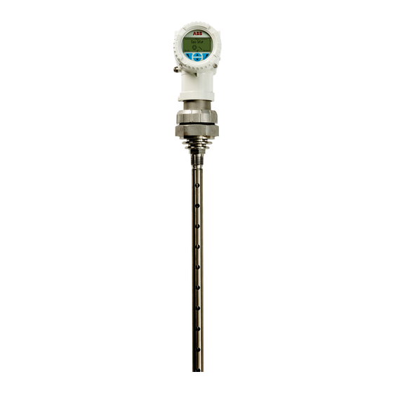
Guided wave radar level transmitter
Hide thumbs
Also See for LWT300 Series:
- User manual (92 pages) ,
- Quick start manual (10 pages) ,
- Quick start manual (4 pages)
Table of Contents
Advertisement
Quick Links
Advertisement
Table of Contents

Related Manuals for ABB LWT300 Series


Summary of Contents for ABB LWT300 Series
- Page 1 — U S E R G U I D E LWT300 series Guided wave radar level transmitter (Modbus)
- Page 2 ABB shall not be liable for errors or omissions contained in its software or guides, any interruptions of service, loss of business...
-
Page 3: Table Of Contents
— Table of Contents 1 Safety Connecting the instrument ....... 28 Upon startup ............31 Definitions ..............1 Personnel ..............3 4 Introducing the user interface Electrical ..............3 Introducing LWT user interfaces ...... 33 Grounding ............4 Accessing menus ..........34 Environmental (WEEE) ...........5 Navigating the instrument display .... - Page 4 Setting data filtering parameters.....51 Configuring HART communication ....71 Selecting maximum level rate ......51 Setting the HART network address ....71 Setting up a median filter ......51 Locating an instrument with tags ....71 Setting up a damping period ...... 52 Browsing communication info .....71 Setting amplitude threshold .......
-
Page 5: Safety
Only by observing all safety information can you minimize the risks of hazards to personnel and/or the environment. Additional safety information is provided in the LWT300 series Hazardous Location Safety Guide (part nº 3KXL001271U0141). Definitions This document uses the following safety notices to bring attention to key technical and safety-related information. - Page 6 WARNING — HIGH VOLTAGE Indicates the presence of electrical energy at voltages high enough to inflict harm on living organisms. WARNING —SHARP EDGES Indicates the presence of sharp edges that could cause personal injury if touched. WARNING — HOT SURFACES Indicates the presence of heat sufficient enough to cause burns.
-
Page 7: Personnel
Personnel WARNING Only qualified and authorized personnel should be put in charge of the installation, electrical connection, commissioning, operation, and maintenance of the instrument. This personnel must hold the necessary qualifications and authorizations, such as training or instruction, to operate and maintain devices or systems in accordance with safety engineering standards regarding electrical circuits, high pressures, aggressive media, and adequate safety systems, based on local and national safety standards, e.g., building codes, electrical codes, etc. -
Page 8: Grounding
• In an industrial environment where EMIs (electromagnetic interferences) are extremely present (e.g., rock quarries, mines, large chemical plants, etc.), ABB recommends the use of noise filters on the DC power supply to the instrument. -
Page 9: Environmental (Weee)
ABB Measurement and Analytics and its affiliates are not liable for damages and/or losses related to such security breaches, any unauthorized access, interference, intrusion, leakage and/or theft of data or information. -
Page 10: Modbus Protocol Disclaimer
To prevent any unauthorized accesses. always ensure that physical access to the instrument and network is properly secured. For cybersecurity reasons, ABB decided not to password protect the Modbus communication protocol in LWT series instruments. General deployment guidelines •... -
Page 11: Introduction
— C h a p t E R 2 Introduction The LWT series of instruments are microprocessor-based level transmitters that use very low power microwave energy to determine the level of the product being measured. A rod, cable or coaxial “probe” is hung into the vessel to act as a waveguide, i.e. - Page 12 — Figure 1 The measurement cycle The head sends a very short pulse of microwave energy through the coupler and down the probe That pulse travels along the length of the probe and, when it encounters the product surface, some of the energy is reflected and travels back towards the coupler .
-
Page 13: First Look
First look Below is a first look at the main components of the LWT series instruments: The head — Figure 2 LWT instrument head Housing cover (terminal side) Nameplate Connection ports (caps removed) Housing cover (display side) Human-Machine Interface (HMI)(LCD and buttons) External ground connection Ex protection mode identification plate Ex protection mode identification sub-plate... -
Page 14: The Coupler
The coupler — Figure 3 Typical 3/4 NPT LWT310 instrument coupler Alignment bumpers Probe attachment 3/4 NPT thread Head coupler Head sensor thread thread socket As shipped — Figure 4 Head-coupler assembly User Guide... -
Page 15: Basic Installation Procedure
Basic installation procedure Here are the basic installation steps described in this guide. The following chapters provide more details. 1 Access and properly secure the installation site (vessel depressurization and cool down, mains power down, etc.) (see page 16). 2 Attach the probe to the head-coupler assembly (see page 19). 3 Slide the probe in the vessel and attach the assembled LWT system on the external flange (see page 21). -
Page 16: Disclaimers
Repairs, alterations, and enhancements, or the installation of replacement parts, are only permissible as far as these are described in this guide. Approval by ABB must be requested in writing for any activities beyond this scope. Repairs performed by ABB-authorized centers are excluded from this article. -
Page 17: Installing The Lwt
— C h a p t E R 3 Installing the LWT The following pages explain how to proceed with a typical physical installation of your LWT instrument. Keep in mind that there are numerous possible installation scenarios; this documentation cannot cover them all. -
Page 18: Environmental Considerations
If the site where the LWT will be installed is subject to severe vibration conditions, harsh environment errors might be flagged (see “Setting process conditions” on page 50). Contact ABB for information on using a remote coupler installed on a bracket to dampen oscillations (see “Installing a remote head LWT instrument” on page 24). -
Page 19: Vessel Considerations
O-ring which presses the braiding against the inside wall of the body, thus ensuring good contact. NOTICE If you plan on using cable glands that are not supplied by ABB, refer to your supplier’s data sheet for proper installation. Vessel considerations •... -
Page 20: Gathering Necessary Tools
Gathering necessary tools To proceed with the installation of a LWT instrument, you need some basic tools such as: • 3 mm hexagonal key • ¼″, 5/16″, 3/8″ and 7/16″ wrenches, or adjustable wrench • Flat head screwdriver (¼″) • Safety footwear and goggles • Protective gloves • ESD protection equipment Accessing the location DANGER The installation area must be secured. -
Page 21: Assembling A Segmented Probe
Assembling a segmented probe Segmented probes are rod probes divided in 1-meter (3.3 feet) segments that must be assembled on site. Each segment is inserted into the vessel at the moment of assembly, starting with the end-of- probe segment. The following explains the assembly procedure. To assemble a segmented probe on site: 1 Slide in the head lock on the set-screw fixed on one of the probe segments. - Page 22 — Figure 6 Tightening probe segments together Through-holes Probe slots 4 Insert the probe assembly in the vessel, making sure that the assembly does not fall in the vessel by inserting a metal pin (not provided) in the through-hole in such a way that the pin rests across the vessel port.
-
Page 23: Attaching A Probe To The Coupler
Attaching a probe to the coupler Depending on your specific application, you might have to install a cable or rigid probe. ELECTROSTATIC DISCHARGES Electronic components are sensitive to electrostatic discharges. Before performing any connection, operators shall make sure that they have discharged all static electricity from their body before touching electronic components. - Page 24 — Figure 8 Screwing in the probe 4 Once all the parts are in place, use two wrenches (one holding the head bolt and the other, the probe slot) to apply the recommended torque (see below) in opposite directions at the same time. —...
-
Page 25: Installing The Lwt Instrument
Installing the LWT instrument NOTICE Installing the LWT system directly on the top of the vessel provides the best return signal. Once the probe and coupler/head assembly have been attached, you need to: 1 Insert the probe end into the flange, down the nozzle and to the bottom of the vessel. 2 Secure the coupler as necessary: –... -
Page 26: Rotating The Hmi
2 Loosen the head adapter by a quarter turn. This should allow the housing to rotate freely. 3 Position the housing in a way that is optimal to your location. 4 Once the housing is in the proper position, re-tighten the head adapter. 5 Re-tighten the head adapter security screw to secure the head adapter. - Page 27 — Figure 12 Four positions for the instrument HMI 0° (default) +90° +180° +270° 5 Properly align the connection pins and gently push back the HMI board on the communication board, making sure that the four plastic locks are properly fixed. NOTICE Be careful not to bend the connection pins (see Figure 13) when pushing the board back in.
-
Page 28: Installing A Remote Head Lwt Instrument
Installing a remote head LWT instrument Certain process conditions (especially high temperatures) warrant the use of a remote head on the LWT300 instrument. Remote head instruments are also very useful for any reason where you might prefer or need to distance the head from the coupler (ease of access, floating roofs, etc.) There are three main steps to installing a remote head instrument: 1 Installing the probe-coupler assembly in the vessel (see “Assembling a segmented probe”... - Page 29 3 Place the instrument head on top of the coupler-head adapter (see Figure 15). NOTICE As much as possible, avoid using PTFE tape on the threaded connection as this type of tape can affect the ground connection between the coupler and the adapter. If PTFE tape is used, it shall be used in a very thin layer to avoid electrically isolating the coupler from the adapter.
- Page 30 7 Connect one end of the coaxial cable to the botton of the head-coupler adapter (see Figure 16). NOTICE When connecting either end of the coaxial cable, we strongly suggest the use of a wrench or pliers. The coaxiable cable bend radius shall not be less than 150 mm (6 in). —...
-
Page 31: Grounding The Instrument
Grounding the instrument The LWT must be grounded in accordance with national electrical codes, using a protective earth (PE) terminal by means of a short connection to an equipotential bonding. The equipotential bonding conductor must have a maximum cross-section of 4 mm² (12 AWG). PE terminals are available inside and outside the instrument housing (see Figure 18). -
Page 32: Connecting The Instrument
Connecting the instrument WARNING All connections must be established in a de-energized state. Before working on the circuit, secure the breaker to prevent any accidental power-up. In an explosion proof/flameproof installation, do not remove the covers while the instrument is energized. ELECTROSTATIC DISCHARGES Electronic components are sensitive to electrostatic discharges. - Page 33 To connect the LWT instrument: 1 Remove the temporary plastic cap from the most convenient of the two electrical connection ports (see Figure 20 on page 29). WARNING In the particular case of explosion proof installations, remove the temporary plastic caps and close the unused opening with a cap certified and appropriately rated for explosion containment.
- Page 34 5 From the connection cable: a Connect the ground cable to the internal PE terminal (if necessary) b Connect the Modbus cables to the COMM A (+) and COMM B (–) terminals. c Connect the positive lead to the PWR + terminal, and the negative lead to the PWR – terminals. 6 Plug and seal the electrical connection ports.
-
Page 35: Upon Startup
Upon startup Upon startup, the LCD turns on, the instrument establishes connection and the display starts showing values on Operator page 1 based on the factory-set configuration. NOTICE For instruments equipped with the through-the-glass (TTG) display option, wait for the HMI calibration process to complete (±30 seconds after power-on) before operating the HMI. - Page 36 Page intentionally left blank...
-
Page 37: Introducing The User Interface
— C h a p t E R 4 Introducing the user interface Chapter 5 and Chapter 6 discuss various configuration options, but first you need a basic understanding of the various ways to interact with the instrument. Introducing LWT user interfaces To configure your LWT instrument, you need to understand the access methods to the parameters that you need to change and what to expect when you reach these parameters. -
Page 38: Accessing Menus
By entering the proper password, you will gain access to features and functions associated with this access level. The Service menu can only be accessed by or under the supervision of, ABB service personnel. The icon adjacent to the provided access level is displayed in the system status area. - Page 39 Selecting an option Options can be selected but not modified. This is the easiest operation to perform: 1 Using the arrow and action keys, move up, down, left or right within a menu. 2 Once you find the option that you want to set, highlight it by using the arrow keys. 3 Press the right action key (OK).
- Page 40 Page intentionally left blank...
-
Page 41: Configuring The Instrument At Startup
— C h a p t E R 5 Configuring the instrument at startup Once the LWT instrument is physically installed and properly powered, you might need to configure the various parameters to better suit your needs if they go beyond the default configuration. The following pages explain the first-time Easy Setup configuration (in more details than the Quick Start guide). - Page 42 2 Press Next. The Set PV screen appears. This sets the type of measurement that you want to make. a Press Edit. The list of available measurements appears (default value: Level). b Scroll up or down the list and highlight the required measurement. c Press OK.
-
Page 43: Configuring The Instrument
— C h a p t E R 6 Configuring the instrument Once the LWT instrument is physically installed and properly powered, you might need to configure the various parameters to better suit your needs if they go beyond the default configuration. The following pages explain how to configure these various parameters from the built-in interface (a.k.a., the HMI). -
Page 44: Configuring Operator Pages
Configuring Operator pages Operator pages display relevant information about ongoing process measurements. The LWT allows you to configure and display up to four different Operator pages. Each Operator page can display bargraphs and/or up to three lines of data. You can scroll automatically between the four Operator pages with the autoscroll feature (see “Enabling Operator page autoscroll”... -
Page 45: Selecting An Operator Page To Display
8 Highlight the value that you want to display and press OK. 9 (if necessary) Repeat steps 6 through 8 to configure all remaining values. Once you have completed the configuration, exit the Display menu. Selecting an Operator page to display If necessary, you can choose which Operator page to display as the default display. -
Page 46: Protecting Access To Instrument Data
Protecting access to instrument data LWT instruments offer a few methods of protecting access to their data. You can set role-based passwords (standard and advanced users) and enable instrument write-protection (software and hardware) from the Access Control menu under the Device Setup menu. —... -
Page 47: Disabling Access To The Service Account
In LWT instruments, the Service account allows access to service-specific functions usually reserved to administrators and ABB troubleshooting experts. It is good practice to disable access to this account and only allow a restricted number of users for this account as it could provide backdoor access and amper the instrument cybersecurity protections. - Page 48 — Figure 33 Accessing the write-protection screw Nameplate Write-protection screw 2 Using a suitable screwdriver, fully press down on the write-protection screw and turn 90° clockwise to activate hardware write protection or, if already activated, 90° counterclockwise to deactivate it. —...
-
Page 49: Setting Dynamic Variables
Setting dynamic variables The LWT instrument can monitor up to four variables. These variables are identified as primary (PV), secondary (SV), tertiary (TV), and quaternary (QV). If you initially configured your LWT instrument with the help of the Easy Setup menu, you have already defined the primary variable (PV). -
Page 50: Configuring The Sensor
Configuring the sensor Certain sensor parameters can be configured to improve measurement accuracy and reliability. This configuration can be performed from the Sensor Setup menu found under the Device Setup menu. Selecting the application category The application category is the type of media in which the sensor will be used. Applications are based on the dielectric constant (DC) value of the medium measured. -
Page 51: Setting The Dielectric Constant Of Upper Media
Setting the dielectric constant of upper media When your application involves measurement of the interface between liquids (e.g., oil on top of water), you must indicate the dielectric constant (DC) of the first liquid that the pulse will encounter (in this case, oil). To do so: 1 Select Device Setup >... -
Page 52: Resetting Echo Tracking
Setting the GPC percentage (static mode) In static GPC mode, the LWT instrument uses a precise percentage (slope correction) that you input as the baseline for gas-phase compensation (for more information, see “Appendix C” on page C93). To set the GPC percentage: 1 Select Device Setup >... -
Page 53: Changing Probe Length
Changing probe length The probe length is already programmed into the instrument. Should you have to physically shorten the probe for any reason, do not forget to change the probe length programmed in the instrument. To do so: 1 Select Device Setup > Application Setup > Probe Length. 2 Press Edit. -
Page 54: Setting Bypass/Sw Pipe Diameter
Setting bypass/sw pipe diameter If installing your LWT on a bypass or stilling well (SW), you need to set the diameter of said bypass/ stilling well. To do so: 1 Select Device Setup > Application Setup > Bypass/SW pipe Diam.. 2 Press Edit. -
Page 55: Setting Data Filtering Parameters
All these conditions are disabled by default. They are all enabled in a similar fashion, as explained below: 1 Select Device Setup > Application Setup > Process Condition. 2 Highlight the relevant process condition and press Edit. 3 Highlight Enable and press OK. Setting data filtering parameters Processes can induce noise in level measurements. -
Page 56: Setting Up A Damping Period
To set a median filter: 1 Select Device Setup > Filtering > Median Filter. 2 Press Edit. 3 Set the number of measurements that you want kept in the filter buffer (between 1 and 50) and press OK. Setting up a damping period The instrument damping filter is designed to smooth out measurement noise in applications with slow dynamics (e.g., liquids with slow waves). - Page 57 Setting a blocking distance The blocking distance is the distance where you do not want the instrument to take measurements because you know that these measurements will include erroneous or useless data (e.g., right at the junction between a nozzle and the inside of the vessel, where a giant pulse usually forms.) To set a blocking distance: 1 Select Device Setup >...
-
Page 58: Managing Lost Echoes
Managing lost echoes A lost echo happens when your instrument loses the signal returning to the sensor. You can set the parameters that help your instrument manage such situations. Period The lost echo period is the time period during which the instrument waits before reacting. To set a lost echo period: 1 Select Device Setup >... - Page 59 — Figure 41 Actual level vs. linearization table points point 3 50 m point 2 15 m point 1 10 m point 0 If Figure 41 was translated in actual values, it could be put in a table as such: —...
-
Page 60: Accessing The Linearization Function
Accessing the linearization function To access the linearization function: 1 Select Device Setup > Linearization > Setup > Output Type. 2 Press Edit. 3 Highlight the measurement value that you want to use (Level, Volume or Flow) and press OK. This activates a series of parameters that will be explained and configured below. -
Page 61: Generating A Linearization Table Automatically
Setting the vessel diameter To set the vessel diameter: 1 Select Device Setup > Linearization > Volume Calculation > Cylinder Diameter. 2 Press Edit. 3 Set the vessel diameter and press OK. Setting the vessel length To set the vessel length: 1 Select Device Setup >... -
Page 62: Saving The Linearization Table
Saving the linearization table To save the linearization table that you just created (see “Setting up linearization points” on page 57): 1 Select Device Setup > Linearization > Saved Tables > Save. 2 Press OK. Your linearization table is saved in memory. Enabling the linearization function To activate the linearization function: 1 Select Device Setup >... -
Page 63: Managing Device Setups
Managing device setups Configuring or reconfiguring your instrument could take a non trivial amount of time. With that in mind, once you have properly configured your instrument, you can save your setup as a baseline configuration that you can revert to if necessary. The following pages explain how to proceed. Saving default user setup To save your current configuration as your default user setup: 1 Select Device Setup >... -
Page 64: Configuring The Lwt300 With A Computer
• Connect ‘TX−’ and ‘Rx−’ LWT guided wave radar level transmitters can be configured with the aid of various software communication tools such as ABB Field Information Manager, a software configurator that can be downloaded at www.abb.com/measurement. With the graphical user interface all configuration possibilities are available. The procedure for program installation is described in the appropriate installation manual delivered with the software. - Page 65 subject to a plausibility check. Immediately after receipt of the transmitter or after changing the configuration, we recommend that you back up the existing configuration on a separate data medium. An RS485 interface will be needed for communication between a PC and the transmitter. •...
- Page 66 Page intentionally left blank...
-
Page 67: Setting Calibration Parameters
— C h a p t E R 7 Setting calibration parameters Part of your instrument measurement accuracy resides in proper calibration of the vessel empty and full states. The values associated with these states are usually configured upon starting the instrument via the Easy Setup menu. -
Page 68: Changing The Empty/Zero Value
— Figure 46 The Calibrate menu Changing the empty/zero value This value (probably set initially from the Easy Setup menu) represents the lowest level measurement value in your vessel. If you set this value first with the Easy Setup menu, you can change it later. To set this value: 1 Select Calibrate >... -
Page 69: Changing The Full/Span Value
Changing the full/span value This value (probably set initially from the Easy Setup menu) represents the highest level measurement value in your vessel (distance from the empty/zero position). To set that value: 1 Select Calibrate > Level Calibration > ↑ Full/Span. 2 Press Edit. 3 Set the value as necessary and press OK. - Page 70 Page intentionally left blank...
-
Page 71: Configuring Communications
— C h a p t E R 8 Configuring communications There are two types of communication at play in the Modbus LWT300 instruments. For general data exchange operations with external computer systems (PCs, flow computers, etc.) communications go over the Modbus protocol (Modbus RTU with 2-wire half-duplex RS-485 serial interface). For instrument configuration (with software tools running on a computer), the HART communication protocol is used (via a RS-485 serial interface). -
Page 72: Toggling Via Hardware
NOTICE For instrument configuration with software tools running on a PC, you must disconnect the LWT from the flow computer/RTU. When you are done configuring the instrument remotely via a HART/RS-485 connection with a PC, you must toggle the communication mode back to Operation; otherwise the instrument will not be able to resume sending data when reconnected to the Modbus network. - Page 73 — Figure 49 Pulling out the HMI board Communication board HMI board 4 On the communication board, set dip switches 3 and 4 to position 1 (see Figure 50). Your LWT instrument is now ready to be configured via your preferred software tool. —...
-
Page 74: Configuring Modbus Communication
Configuring Modbus communication The following subsections refer to the Modbus configuration of your LWT300 instrument. You will also find more information about Modbus registers in “Appendix B” on page B89. Setting the Modbus network address To set the instrument address so that it can be identified on a network: 1 Select Communication >... -
Page 75: Setting The Swap Mode
NOTICE The LWT series MODBUS/HART FDI package is required to communicate via HART. You can download it from https://new.abb.com/products/measurement-products/level/ guided-wave-radar-level-transmitters/lwt300-series-guided-wave-radar. Setting the HART network address To set the instrument address so that it can be identified for configuration purposes with your software tool: 1 Select Communication >... - Page 76 Page intentionally left blank...
-
Page 77: Maintenance And Troubleshooting
Additionally, no user/operator adjustments inside LWT instruments are necessary or recommended by ABB. Service tasks that are not explained in this documentation are to be performed at the factory by qualified service personnel only. - Page 78 The following table gives you a quick way to identify the basic problems. — Table 3 Basic problem identification from LCD Icon Description Error text Error/Failure Functional check Configuration (e.g., during simulation) Electronic Operation process Out of specification transmitter Maintenance required To obtain more information about the currently diagnosed error, you need to access the Diagnostics operator menu.
-
Page 79: Browsing The Diagnostics History
Browsing the diagnostics history To browse through the diagnostics history: 1 From the Diagnostics menu, select Diagnostic History. — Figure 53 The Diagnostic menu The last event message appears. To browse through all event messages, press the Up and Down arrow keys. -
Page 80: Event Codes And Recommendations
Successful sensor reboot S062.019 Surface inside blocking distance Check process conditions and device config. F237.020 Sensor Board communication error. Restart sensor. If condition persists, call aBB F233.023 Electronics NV Failure the electronics must be replaced; call aBB. S082.024 Weak echo amplitude Check installation and process conditions. -
Page 81: Masking Classes Of Events
Masking classes of events Instrument event codes are recorded according to the NAMUR classification (see page 75). By default, these events are displayed in the diagnostic history, but you can choose to mask certain classes of events. Masked events are still recorded and kept in the event history log. To do so: 1 Select Diagnostics >... -
Page 82: Diagnosing From A Waveform
Diagnosing from a waveform Most echo-related problems, as listed in Table 4, can also be diagnosed with the help of the integrated waveform displayed on the LCD. Waveform management is performed from the Diagnostics menu. — Figure 55 Accessing the waveform display Introducing the waveform display The waveform display illustrates the signal traveling along the probe. -
Page 83: Accessing The Waveform Display
Accessing the waveform display You access the waveform display from the Diagnostics menu by selecting around which point along the waveform you want to center your main marker. • To access the waveform display, select Diagnostics > Waveform > [desired centering location]. (At Sensor Ref. -
Page 84: Performing Simulations And Tests
Performing simulations and tests The simulation tools, found in the Simulation menu under the Diagnostics menu, help confirm proper communication of measured values. There are six standard simulations all performed in a similar way (distance, level, ullage, interface, volume and flow). All are explained below. —... -
Page 85: Electronics Temperature
This does not preclude your instrument from working properly. Setting distance calibration parameters LWT300 probes are calibrated before leaving the plant. ABB service personnel will inform you if distance calibration needs to be performed. Maintenance and troubleshooting... -
Page 86: Accessing Device Information
Accessing device information When calling an ABB service representative, you might be asked to provide any of the following information, available from the Device Info menu: — Figure 58 The Device Info menu • Manufacturer • Name • Model • Device ID •... - Page 87 — A p p E N D I X A LCD menu tree The following pages provide an overview of the various menu items accessible through the instrument liquid crystal display (LCD). First-level menu Menu item Details Main chapters access Level page a83 Easy Setup page a83...
- Page 88 Device Setup menu Item Submenus access Control Standard password advanced password Reset password Service account Write protect Software Wp hardware Wp Dynamic Variables Set pV Set SV Set tV Set QV Level Unit Flow Unit Volume Unit temperature Unit Sensor Setup application Category Gas phase comp.
- Page 89 Item Submenus Safety Settings Blocking Distance Safety Distance Safety Dist. Reaction Echo Lost period Echo Lost Reaction alarm Delay Linearization Setup table State Output type Input Unit Output Unit Maximum Volume Calculation Cylinder Orientation Cylinder Diameter Cylinder Length Gen. Linearization Set Lin.
- Page 90 Calibrate menu Item Submenus Level Level Calibration ↓Empty/Zero ↑Full/Span Level Offset Sensor Offset Distance Calibration Distance Offset Calibration Distance Slope Calibration Diagnostics menu Item Submenus Waveform at Sensor Ref point at Level at Distance at End of probe Record Waveform Level Echo Selection Current Distance Select previous Echo...
- Page 91 Item Submenus Device Status probe Length Status Electronic temp. Electronic temp. Min Electronic temp. Max Electronic temp. Reset Min/Max total Run time Self test Start Self test Result Self test Device Info menu Item Manufacturer Name Model Device ID Device Serial Number Order Code Manufacturing Date Installation Date...
- Page 92 Communication menu Item Submenus haRt Devices address Message Last Command Device ID Manufacturer ID Device type Descriptor Device Revision haRt Revision Modbus address Baud Rate parity Stopbit RespDelay time address Offset Swap Mode Device Mode A88 User Guide...
-
Page 93: Modbus Registers
— A p p E N D I X B Modbus registers NOTICE The map register offset in this Appendix is Base 0 (first register address is at 0). Holding registers The Holding registers consist of 16 bits. They can be read and written. The address (1 byte) is sent before each command. -
Page 94: Input Registers
Input registers The input registers consist of 16 bits. They can only be read out. The address (1 byte) is sent before each command. A CRC (2 bytes) is sent after each command. PV, SV, TV and QV can be adjusted via the sensor FDI. - Page 95 On-Board DIp Switch Status hMI Software 10001 UINT16 hMI Software Revision Revision tpROC alarm 10002 UINT16 External temperature additionnal status 1 Registers 3001, 3002, 3003, 3004, 7001, 7003 and 7005 are used to emulate an ABB LevelMaster Modbus registers B91...
- Page 96 Page intentionally left blank...
-
Page 97: C Gas Phase Compensation Static
— A p p E N D I X C Gas phase compensation static factors The following tables explain provide the necessary gas phase compensation (GPC) static factors. Dielectric constant of steam Temperatrure Pressure °C °F 1 bar 2 bar 5 bar 10 bar 20 bar... - Page 98 Page intentionally left blank...
-
Page 99: Dielectric Constants Chart
— A p p E N D I X D Dielectric constants chart The dielectric constant of common fluids is indicated below. Dielectric constants are generally influenced by: • temperature • moiture levels • electrical frequency • part thickness Fluid Temperature in °C (°F) Dielectric Constant ( ε ) acetal... - Page 100 Fluid Temperature in °C (°F) Dielectric Constant ( ε ) ammonia solution 25% 31.6 amyl amine aniline 20 (68) anisole antimony hydride argon arsine arsole azoxybenzene 36.1 (97) Benzene 20 (68) Bromine 20 (68) Butane -1.11 (30) Butanoic acid Caproic acid 71.1 (160) Caprylic acid Carbon disulfide 2.64...
- Page 101 Fluid Temperature in °C (°F) Dielectric Constant ( ε ) Gasoline, gas 21.1 (70) Glycerine 47 – 68 Glycerol 25 (77) 42.5 Glycerol water Glycol heptane 20 (68) hexane –90 (–130) hexanol 25 (77) 13.3 hydrazine 20 (68) 52.0 Iodine 11.1 Isopropyl alcohol (CH₃)₂CH₂O 18.2 Jet fuel 21.1 (70)
- Page 102 Fluid Temperature in °C (°F) Dielectric Constant ( ε ) toluene 2.0 - 2.4 transformer oil turpentine (wood), white spirit 20 (68) Vacuum (by definition) Vinegar Water 20 (68) 80.4 Water 360 (680) Water, demineralised 29.3 Water, heavy 78.3 Water – oil emulsion Wine D98 User Guide...
-
Page 103: Pt100 Temperature Sensors
— A p p E N D I X E PT100 temperature sensors The temperature sensor circuit (PT100) must be connected in accordance with the requirements of the CSA certificate. The temperature sensor circuit (PT100) and the digital output (pulse/limit value output) must be connected in accordance with the requirements of the Ex certificate. - Page 104 Page intentionally left blank...
- Page 105 Page intentionally left blank...
- Page 106 Page intentionally left blank...
- Page 108 We reserve the right to make technical changes or modify the contents of this document without prior notice. With regard to purchase orders, the agreed particulars shall prevail. ABB does not accept any responsibility whatsoever for potential errors or possible lack of information in this document.