Advertisement
Quick Links
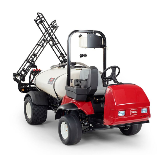
Finishing Kit
Foam Marker for Multi Pro
Model No. 136-0457
Note: The Foam Marker Kit is required for the installation
of this product. Contact your Authorized Toro Dealer for
more information.
WARNING
CALIFORNIA
Proposition 65 Warning
This product contains a chemical or chemicals
known to the State of California to cause cancer,
birth defects, or reproductive harm.
Safety
Note: Determine the left and right sides of the machine
from the normal operating position.
© 2016—The Toro® Company
8111 Lyndale Avenue South
Bloomington, MN 55420
®
Safety and Instructional
Decals
Register at www.Toro.com.
1750 Turf Sprayer
Safety decals and instructions are easily
visible to the operator and are located near
any area of potential danger. Replace any
decal that is damaged or missing.
125–8112
1. Right boom
2. Both booms
Original Instructions (EN)
All Rights Reserved *3411-661* A
Printed in the USA
Form No. 3411-661 Rev A
Installation Instructions
3. Left boom
decal125-8112
Advertisement

Related Manuals for Toro 136-0457


Summary of Contents for Toro 136-0457
- Page 1 1750 Turf Sprayer Model No. 136-0457 Installation Instructions Safety and Instructional Note: The Foam Marker Kit is required for the installation of this product. Contact your Authorized Toro Dealer for Decals more information. WARNING Safety decals and instructions are easily...
-
Page 2: Installation
Installation Loose Parts Use the chart below to verify that all parts have been shipped. Procedure Description Qty. – No parts required Prepare the machine. Bracket Bolt (5/16 x 1 inch) Install the foam-marker compressor on Washer (3/8 inch) the bracket. Nut (5/16 inch) Foam marker (sold separately) Carriage bolt... - Page 3 Installing the Foam-Marker Installing the Compressor and Compressor on the Bracket Bracket on the Machine Parts needed for this procedure: Parts needed for this procedure: Bracket Carriage bolt Bolt (5/16 x 1 inch) U-bolt Washer (3/8 inch) Flange nuts (3/8 inch) Nut (5/16 inch) Spacer Foam marker (sold separately)
- Page 4 g200501 Figure 3 1. Pump suction hose 3. R-clamp 2. Bracket 4. Flange nut (3/8 inch) 5. Place the U-bolt onto the machine as shown in Figure g200498 Figure 4 1. Flange nuts (3/8 inch) 2. U-bolt 6. Place the bracket onto the U-bolt and secure it with the 2 flange nuts (3/8 inch).
- Page 5 Routing the Wire Harness and Installing the Switches Parts needed for this procedure: Wire harness Switch bracket Rocker switch Paddle switch Bolts (M6) Fuse, 15 amp Procedure Note: Lift the seat to route the wire harness. 1. Route the wire harness from the foam-marker compressor behind the ROPS and under the guard plate (Figure g200673 Figure 5...
- Page 6 2. Connect the ground wire and relay switch and insert the 15 amp fuse into the fuse block (Figure g200670 Figure 6 3. Relay switch 1. Ground wire 2. Fuse, 15 amp 3. Connect the blade connector to the socket connector of the fuse block. 4.
- Page 7 6. Route the harness under the panel on the floor plate and up to the steering column (Figure g200672 Figure 8 7. Attach the paddle switch bracket to the steering column with the 4 bolts (M6) as shown in Box A of Figure g200698 Figure 9...
-
Page 8: Operation
Operation Using the Controls Foam paddle switch—activates the compressor, generating a flow of foam and air to the right or left boom section (Figure Foam on/off switch—activates the compressor, generating a flow of foam to both of the boom sections simultaneously (Figure Indicator markings—located on the side of the tank;...